1
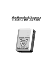
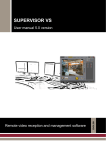
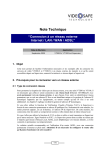
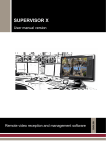
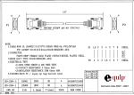
VT100 v2.6
User Manual
VT100 v2.6
User Manual
VT100 User Manual
3
INDEX
1.
INTRODUCTION................................................................................................................................................... 5
1.1
1.2
1.3
1.4
1.5
1.6
1.7
2.
FUNCTIONAL DESCRIPTION ........................................................................................................................... 8
2.1
2.2
3.
DIFFERENT VT100 MODELS ............................................................................................................................. 5
SECURITY ADVICES........................................................................................................................................... 6
MAINTENANCE OF THE EQUIPMENT .................................................................................................................. 6
LEGAL CONSIDERATIONS .................................................................................................................................. 6
ELECTROMAGNETIC COMPATIBILITY (EMC) .................................................................................................... 6
LIABILITY ......................................................................................................................................................... 7
ADDITIONAL INFORMATION .............................................................................................................................. 7
BASIC WORKING SCENARIO .............................................................................................................................. 8
FUNCTIONALITY OF THE VT100 EQUIPMENT .................................................................................................... 9
PHYSICAL DESCRIPTION ............................................................................................................................... 11
3.1
FRONT VIEW OF THE MODELS VT104 AND VT104-RAM ............................................................................... 11
3.1.1
LEDs description ...................................................................................................................................... 12
3.1.2
Images Under Custody Lock (only in the VT104 model).......................................................................... 12
3.2
REAR VIEW (CONNECTIONS)........................................................................................................................... 12
3.2.1
Power supply ............................................................................................................................................ 13
3.2.2
Communication lines ................................................................................................................................ 13
3.2.3
Video signals and domes .......................................................................................................................... 14
3.2.4
Alarm inputs.............................................................................................................................................. 15
3.2.5
Relay outputs ............................................................................................................................................ 16
3.2.6
Alarm inputs and relay outputs pins layout .............................................................................................. 17
4.
INSTALLATION OF THE VT100...................................................................................................................... 18
4.1
4.2
4.3
4.4
CONTENTS OF THE VT100 BOX....................................................................................................................... 18
INSTALLATION ................................................................................................................................................ 19
VERIFYING THE INSTALLATION....................................................................................................................... 20
RIGHT SIDE VIEW (FACTORY SETTINGS).......................................................................................................... 21
APPENDIX 1 – TECHNICAL SPECIFICATIONS ................................................................................................... 22
APPENDIX 2 – CONFIGURING A VT100-N UNIT WITH LAN CONNECTION................................................ 24
INTRODUCTION ............................................................................................................................................................. 24
REQUIRED ELEMENTS FOR THE LAN CONNECTION ....................................................................................................... 24
INSTALLING AND CONFIGURING THE LAN COMMUNICATION IN A VT100 UNIT ............................................................ 25
CONFIGURATION PROCESS OF THE LAN ADAPTER BY IPSET.EXE ................................................................................. 26
How to detect potential errors in the configuration of the LAN adapter ................................................................ 28
How to change the IP address ................................................................................................................................ 29
Changing the equipment from one local network to another.................................................................................. 29
INTEGRATION OF THE VT100 LAN EQUIPMENT IN THE SUPERVISOR ............................................................................ 29
VT100 User Manual
4
1. Introduction
This manual contains detailed information about how to install the units VT104 (recordertransmitter), VT104-RAM (transmitter) and VT104-LITE (the lowest-cost transmitter). Every
generic mention to the VT100 will always refer to all the models, and whenever there is a
difference between these models, it will explicitly indicated.
Chapter 2 gives an overview about the features of the VT100, and chapter 3 offers detailed
information about the physical appearance of the VT100 and a description of all used connectors.
Chapter 4 contains the step-by-step procedure to install the VT100 equipment.
The appendices comprise the technical specifications of the equipment and the specifications for
the TCP/IP equipments’ connection.
The equipment is supplied with the professional application Supervisor, which enables a
conventional PC to display the video images transmitted by the VT100 equipment and to access
to the video sequences stored in its hard disk. This application encloses VideoSetup, a
configuration tool to program the equipment.
For more information about managing and programming the equipment, please refer respectively
to the Supervisor and VideoSetup User Manuals.
1.1 Different VT100 models
You can read which particular VT100 model you are using in a label located on the bottom of the
equipment. It has the following format:
VT104 – Com
VT104-RAM – Com
VT104-LITE
-Com indicates the communication option installed (modem or internal adapter). It can be:
-
T for PSTN connection. Optionally it might be –TA, to indicate that the model
includes bidirectional audio transmission. This audio option is only available
for PSTN connections.
-
D for ISDN connection
-
N for LAN connection
The VT104 model, with hard disc, is able to transmit and record.
The VT104-RAM model, without hard disc, is a transmitter, though it is also able to record a
small amount of sequences in its memory.
The VT104-LITE model is similar to the VT104-RAM-T (only PSTN communication) with some
simplifications that will be later described.
All the models permit the connection of 4 cameras.
VT100 User Manual
5
1.2 Security advices
Verify that the power adapter provided with your equipment matches the voltage
specifications of your power source. DO NOT ATTEMPT TO USE THE
EQUIPMENT WITH A POWER SUPPLY OTHER THAN THE ONE
PROVIDED BY THE MANUFACTURER!
The electric current socket must be easily reachable and close to the equipment.
Do not use the equipment in extreme environments where high temperature or high
humidity exists. Use the equipment at temperatures within +5º C - +40º C (41º F - 104º
F), humidity below 90 % and properly ventilated. Do not block or cover the lateral and
rear openings of the equipment.
Do not attempt to disassemble the equipment. To prevent electric shocks, do not
remove screws or covers. There are no user-serviceable parts inside. Contact the
qualified service personnel for maintenance.
Handle the equipment with care. Do not strike it or shake it, as this may damage it.
The equipment must not be exposed to drop or splash. Besides, objects filled with
liquids, such as glasses, must not be placed onto the equipment.
Protect the equipment from water or dust. Do not use it in wet environments. Do take
immediate action if the equipment becomes wet. Turn the power off and refer servicing
to the qualified service personnel.
1.3 Maintenance of the equipment
Inside the equipment there are two fuses marked as F601 and F602:
F601: 24V and 3A auto motion quick fuse.
Protects the general power supply (12V).
F602: 12V and 1A auto motion quick fuse.
Protects the internal modem power supply (5V)
1.4 Legal considerations
The use of CCTV (Closed Circuit Television) can be legally limited. The law varies from country
to country; check the law applicable in your country before you install the VT100.
Foreseeing legal limitations, the equipment may be configured to delete automatically the stored
video sequences in order to avoid their preservation beyond the permitted time limit.
1.5 Electromagnetic compatibility (EMC)
Europe – The CE mark is affixed to the enclosed product to confirm compliance with the
following European Community Directives for a Class B digital device: EN55022/1994, related
to radiated emission and EN50082-1/1997 related to residential, commercial, and light industry
immunity.
VT100 User Manual
6
USA – This equipment has been tested and found to comply with the limits for a Class B digital
device, pursuant to part 15 of the FCC Rules. These limits are designed to provide reasonable
protection against harmful interference in a residential installation.
This equipment generates, uses and can radiate radio frequency energy and, if not installed and
used in accordance with the instructions, may cause harmful interference to radio
communications. However, there is no guarantee that interference will not occur in a particular
installation.
If this equipment does cause harmful interference to radio or television reception, which can be
determined by turning the equipment off and on, the user is encouraged to try to correct the
interference by one or more of the following measures:
Î Reorient or relocate the receiving antenna.
Î Increase the distance between the equipment and receiver.
Î Connect the equipment into an outlet on a circuit different from that to which the receiver is
connected.
Î Consult the dealer or an experienced radio/TV technician for help.
CAUTION!
The Federal Communications Commission warns the users that changes or modifications to the
equipment not expressly approved by the party responsible for compliance could void the user's
authority to operate the equipment.
This unit has as associated accessory a shielded video cable, which is required in order to ensure
compliance with FCC (Federal Communication Commission) rules.
1.6 Liability
Every care has been taken in the preparation of this manual; if you detect any inaccuracies or
omissions, please inform us at the address that can be found in the warranty of this manual.
Visual Tools cannot be held responsible for any technical or typographical errors and reserves the
right to make changes to the product and manuals without prior notice. Visual Tools makes no
warranty of any kind with regard to the material contained within this document, including, but
not limited to, the implied warranties of merchantability and fitness for a particular purpose.
Visual Tools shall not be liable or responsible for incidental or consequential damages in
connection with the furnishing, performance or use of this material.
1.7 Additional information
To find out more about the VT100 please refer to www.videosafe.net on the Internet.
VT100 User Manual
7
2. Functional description
2.1 Basic working scenario
The VT100 is a digital video recording and transmission compact equipment that works through
telephone lines. It has been designed for the tele-surveillance of medium size remote installations
such as bank branches, small shops or sensitive areas of large buildings.
Fig. 1 shows the basic working scenario of a VT100, which consists of a central security station
with a Supervisor workstation communicated through communications network with a remote
installation in which there is a VT100.
CAMERAS
COMMUNICATION
NETWORK
SUPERVISOR
WORKSTATION
VT100
ALARM INPUTS AND
RELAY OUTPUTS
ALARM
PANEL
Fig. 1 – Basic scenario of a VT100 equipment
The Supervisor workstation works with the Supervisor application, a reception software that is
common to all equipments of the VT range, and includes VideoSetup, the configuration tool of
these equipments. The remote installation is equipped with a VT100 equipment connected to
CCTV cameras. It has a connection to security sensors, such as PIR detectors, door contacts,
seismic detectors, etc. These devices are connected to an alarm panel that sends the alarm
conditions to the VT100 equipment by using the 8 alarm inputs the equipment is provided with.
Besides, the equipment is provided with 4 relay outputs that enable the switching on and off of
remote lights or any other similar devices, which is a practical and effective tool for telesurveillance of unattended sites.
The communication between the Supervisor and the equipment provides a bidirectional
transparent channel canal allowing the remote control of domes and other devices.
Note1 :
The VT104-LITE mode only has two alarm inputs and one relay output, and it does not have
bidirectional transparent channel.
Note 2:
The I/O devices can also be connected directly into the VT100 in case no alarm panel is present. But
keep in mind that the VT100 is not intended to supply the functionality of an alarm panel.
VT100 User Manual
8
2.2 Functionality of the VT100 equipment
The VT100 equipment is a compact equipment of digital video recording on hard disk that
integrates the functions of a convectional video recorder, a multiplexer and a sequencer all
together in an unique cost-effective solution.
Communication
The equipment is able to transmit images to a Supervisor receiving station by using the
conventional telephone lines (PSTN or ISDN) or through TCP/IP with connection to a local
network LAN, being for each type of communication a specific model of VT100 equipment
equipped with the appropriate adapter or modem. The VT104-LITE only admits PSTN
connection through.
With PSTN lines the unit offers two features related to the caller id telephone line service: quick
answer, to identify incoming calls from a given Supervisor and answer immediately, and
callback, to start the communication with a given Supervisor upon receiving a call from it.
With TCP/IP connections, automatic management of dynamic IP address.
Image recording
The image recording of the equipment can take place simultaneously from up to four black and
white or color (PAL or NTSC) cameras, which do not need to be synchronized. The recording
conditions and their frame rate (images per second) can be individually specified for each camera
depending on calendars or timetables (time lapse) and/or depending on the activation of external
events.
Timetables allow for the specification of different recording frequencies depending on opening
hours of the public places or shops. External events are generated by devices connected to the
on/off digital alarm inputs of the equipment, such as presence detectors, door contacts, laser
barriers, etc.
Model VT104
The equipment stores in its hard disk the recorded images coming from each camera as
independent video sequences for the period of time programmed by the user, whose maximum is
366 days. The VT100 equipments have an automatic deleting tool that erases the sequences that
have exceeded the configured period. Also, in order to protect the images acquired during an
alarm situation from being deleted beyond their programmed deadline, the VT100 has an “Images
under custody” function with which the images are preserved by blocking the recording utility of
the equipment.
Models VT104-RAM / VT104-LITE
The VT104-RAM does not have hard disc, but it is able to record in memory 4 sequences up to
35 images each. The oldest sequences are automatically erased when new sequences are recorded.
Given the small number of sequences that can be stored, only event recording, but no time lapse,
is available.
Image Transmission
The advanced image compression system integrated in the VT100 enables the equipment to
transmit a great number of high quality images per second to the receiving station (up to 5
frames/s. depending on the available bandwidth and the recording configuration) It can achieve
this high performance because only the changes of the images with regard to the previous ones
are transmitted.
VT100 User Manual
9
The access to the images is immediate and the image transmission to the receiving station does
not interrupt the recording that is taking place.
The communication can be established from the video receiving station at operator request and,
once the connection has been established, the equipment is ready to transmit live images coming
from the cameras or the images previously stored in its hard disk.
The communication can also be established from the VT100 unit, when the callback option has
been activated or when an event that has been associated to an alarm sign is activated. Then the
equipment automatically sends to the receiver station the images related to that event for a Visual
Alarm Verification (VAV).
Remote Control
Communication between the Supervisor and the VT100 equipment offers a bidirectional
transparent channel allowing remote control of domes and other external devices, like anti-theft
systems (EAS), point-of-sale terminals, etc. The VT104-LITE model does not offer transparent
channel nor the possibility of remote control.
Audio
As an option, there is the VT100-TA (PSTN connection with Audio) that includes the possibility
to transmit bidirectional audio using DSVD (Digital Simultaneous Voice and Data).
For further information, please refer to the technical note “ Installation and use of the PSTN audio
of the VT100” available at www.videosafe.net.
Security (VT104 model)
The VT100 reports automatically the unexpected overflow of the hard disk. In this case, the
equipment continues working normally and as new sequences are being recorded in the hard disk,
the eldest sequences are deleted.
Autotest signal
Periodical test of the units’ status by calling a Supervisor post via any communication to report
any failures or anomalies.
Likewise, the fourth relay output can be configured to alert possible anomalies of the unit, i.e. in
order to be monitored from an alarm panel.
Configuration process
The configuration of the equipment and the control of the calling conditions, automatic activation
of the relay outputs, etc., can be carried out remotely with the configuration tool VideoSetup of a
Supervisor receiving station.
VT100 User Manual
10
3. Physical Description
This chapter describes the front, the rear and the right side view of the VT100. You will find
detailed information about the available connectors.
3.1 Front view of the models VT104 and VT104-RAM
Below you find a picture of the front view of the VT100 equipment.
Images under
custody
Power On
HDD Recording
Modem Ready
Carrier
Detect
Receive Data
Transmit Data
Fig. 2 – Front View of the VT104
Power On
Modem Ready
Carrier
Detect
Receive Data
Transmit Data
Fig. 3 – Front View of the VT104 –RAM / VT104-LITE
On the front of both VT100 models you will find the following LEDs:
y
Power On LED: ON
y
Modem LEDs: TR (Modem Ready), CD (Carrier Detect), TD (Transmit Data), RD (Receive
Data).
On the front of the VT104 model you will find also:
y
Hard disk recording LED: REC
y
Images Under Custody lock
VT100 User Manual
11
3.1.1 LEDs description
The "Power On" LED indicates that the equipment is switched on.
The “HDD Recording” LED indicates that the equipment is accessing the hard disk, normally for
storing images. This led can also light when the equipment is starting up or reading stored
sequences to transfer them to a Supervisor.
The four lower LEDs show the connection status of the modem. The Modem Ready (TR) LED
should always stay on. For more details, please refer to the section 4.3 of this manual.
3.1.2 Images Under Custody Lock (only in the VT104 model)
The “Images Under Custody” lock allows you to freeze the stored images in the Hard Disk. If
Images under custody mode is activated, new sequences cannot be recorded on the disk.
This function is used to keep the recorded images of a situation beyond their configured
maximum time. To activate and deactivate the custody of images, proceed as follows:
Î To activate the images custody, turn the lock to the position “Images under custody” using
the key provided with the unit. The VT100 will restart automatically and protect the stored
images by blocking new recordings. Only live video images will be displayed.
Î To set the equipment again in the normal operation mode, turn the key to its normal
position. The unit will restart automatically and will return to its normal functionality.
The state of the custody lock is visible from the reception software by an icon that appears on the
incidences panel of the Supervisor application. After a connection to a VT100 unit has been
established, this panel will show the icon of an open padlock if the equipment is working in a
normal mode, or a locked padlock if the recording function has been protected and blocked-up by
using the under custody lock.
3.2 Rear view (Connections)
Below you will find a diagram of the rear side of the VT100. The VT104-LITE does not have
power switch, RS232 or digital I/O leds, and it only has two alarm inputs and one relay output.
Power switch
Power supply
connector
Phone
jack
RS232
- NullModem
- Remote control
Digital Input/Output
Camera 2
Camera 1
Digital I/O LEDs
Fig. 4 – Rear View of the VT100
VT100 User Manual
12
Camera 3
Camera 4
Switches for 75 Ω on/off
3.2.1 Power supply
The power adapter to be used must be the universal power adapter supplied with the VT100
equipment. Do not attempt to use the equipment with a power adapter other than the one provided
by the manufacturer!
3.2.2 Communication lines
The connection of the communication is different (See Fig. 5) depending on the VT100 model
(do not forget that the VT104-LITE, regarding communications, is equivalent to a VT104-RAMT without NullModem):
There are different models of VT100 equipments:
y
-T: PSTN modem for a conventional telephone line
y
-D: ISDN adapter for a digital telephone line
y
-N: TCP adapter for connections through a local network.
The modem or adapter is internal in all models and the appropriate cable is provided along with
each unit. The telephone jack model and its icon are at the rear side of the VT100.
It is provided with all equipments (except the VT04-LITE) a NullModem cable for local
connection from a supervisor computer to the remote equipment, to be connected to the RS232
port, port that can be used instead for remote control of domes or other devices.
z
Model -T, with a PSTN modem (conventional telephone line)
A VT100 equipment for PSTN communication is equipped with a RJ11 connector and the
appropriate cable (red cable).
z
Model -D, with an ISDN adapter (integrated system for digital networks)
A VT100 equipment for ISDN communication is equipped with a RJ45 connector (wider than the
RJ11 connector) and the appropriate cable (green cable).
Other devices may share an ISDN line using the MSN (Multiple Subscriber Number) method.
This option can be enabled in your VT100 equipment by using the VideoSetup configuration tool
of the Supervisor application.
z
Model -N, with a LAN adapter (local area network)
A VT100 equipment for TCP/IP communication is equipped with a RJ45 connector and the
appropriate cable (blue cable).
For the installation and configuration processes of these equipments, please refer to appendix 2 of
this manual.
PSTN
ISDN
LAN
Fig. 5 – PSTN, ISDN and LAN communication connection
VT100 User Manual
13
z
NullModem connection
All VT100 equipments (except the VT04-LITE) have a RS232 port that has been configured to
work directly with a NullModem cable. You should be able to connect to the equipment locally
from the Supervisor without having to change the configuration of the VT100. Also you need to
make sure that the Supervisor has been configured to work with NullModem.
Connect the NullModem cable, which you find in the box, to the VT100 and to your PC and you
will be able to connect to the VT100 equipment from your Supervisor by selecting the
“NULLMODEM” option.
Warning!
Two Supervisors cannot connect simultaneously to the same equipment. If the VT100 is connected to
a Supervisor via NullModem, no other Supervisor will be able to connect to this equipment using
another communication channel (PSTN, ISDN or TCP) and vice versa.
If you have configured your RS232 port for remote control (domes or transparent channel) you will
not be able to use it as NullModem.
The equipment testing and configuration can also be done from a remote Supervisor, using the
appropriate communication line (PSTN, ISDN or TCP/IP). NullModem is an aid to ease the
equipment local maintenance.
Refer to the Supervisor User Manual and the VideoSetup User Manual respectively to get
information about supervising and configuring the equipment.
z
Caller-ID: Quick answer and callback
With PSTN connections where the “Caller Id” service is activated the unit can have different
behaviors when receiving a phone call:
y The quick answer option allows the unit to respond immediately to certain calling numbers.
This is useful to share the telephone line with other devices.
y The callback option allows the unit to make the phone call on request of certain calling
numbers, if only rings once or twice. If the number of rings is 3 or more, the phone call will be
processed normally.
If neither quick answer nor callback services are activated, the unit will answer the call at the
defined number of rings.
To configure these features, please consult the VideoSetup manual.
3.2.3 Video signals and domes
The equipment has 4 video inputs (2 for VT102) for black and white or color cameras (PAL or
NTSC format) with no need of being synchronized. The cameras connected to the equipment
must be all PAL or all NTSC. The detection of the camera format is automatically performed
during the equipment start-up.
The cable connecting each camera to the VT100 equipment must be a 75 Ω coax cable, and must
have a male BNC connector at the equipment end.
Each connection or splice produces a slight change in the impedance at that point; so all the
cables used must be one-piece cables, without splices or derivations.
To match the cable impedance, each camera input is loaded with a 75 Ohms terminator in the
VT100 (see Fig. 6). However, for cases in which the camera signal connected to the VT100 is
also connected to other equipments (for instance, to a TV monitor) a switch allows for the 75
VT100 User Manual
14
Ohms of the VT100 to get disconnected (see Fig. 6) in order to avoid too much load of the cable.
Any error in the adaptation of impedance will produce unwanted side effects, or even
unacceptable effects on the image: ghosting or ringing on the image edges or even a loss of the
image.
75 Ohms inserted
(factory layout)
75 Ohms
removed
Fig. 6 – 75 Ohms switch
Note:
To operate on the 75 Ohms switches you can use the screwdriver provided.
z
PTZ control (domes)
The VT100 equipment (except the VT04-LITE) also allows the connection of up to 4 PTZ
cameras (domes) from the same manufacturer or, if through the appropriate matrix, from different
ones, but there is no auto-detection for this type of cameras. The connection of the domes to the
VT100 equipment is made through the RS232 port. To do so, a converser from the RS485 or
RS422 standard to the RS232 standard may be required. When using the RS232 port for domes
connection, communications via NullModem become useless, so the communication must be via
TCP/IP, ISDN or PSTN.
CONTROL
RS485/RS422
VIDEO
RS232
VIDEO
RS232
VidIn
VidIn
VIDEO
VidIn
In order to control and move domes you fill have to previously configure your VT100 using the
VideoSetup and the reception software (Supervisor). You will find the necessary information in
the manuals of these applications (VideoSetup and Supervisor).
3.2.4 Alarm inputs
The equipment has 8 alarm inputs (two for the VT104-LITE) without galvanic isolation, (see the
pins layout diagram of the Fig. 7), so the activation/deactivation of the digital signals requires
voltage-free contacts, thus allowing for the isolation of the sensor and the equipment.
There are 8 LEDs situated over the alarm inputs to show the status of each one of them. The
VT104-LITE does not have these leds.
VT100 User Manual
15
3.2.5 Relay outputs
The equipment is provided also with four relay outputs (one for the VT104-LITE). Each relay
provides normally open (NO) and normally closed (NC) contacts. Their electrical features are as
follows:
y
y
Maximum switching voltage: 24V AC/DC
Maximum switching current: 1A
There are 4 LEDs situated over the relay outputs to show the status of each one of them. The
VT104-LITE does not have these leds.
Diagnostics Output
The equipment offers the possibility to monitor certain internal states through one of the relay
outputs (output 4), being so able to send this information to the Supervisor. This signalisation is
not exclusive, that is to say, several states can be associated to the same output. The states than
can be monitored are:
-
disk failure
unit not operative
without recording during NN hours, being NN an entire value configurable by the user
VT100 User Manual
16
3.2.6 Alarm inputs and relay outputs pins layout
In the next diagram you will find the pins layout for the connection of the alarm inputs and the
relay outputs. For the VT104-LITE this layout consists of just two alarm inputs and one relay
output.
Installation
Terminal Connectors
VT100
PIN
ASSOCIATED SIGNAL
1
Alarm input 1
2
GND (1,2)
Cont 2
3
Alarm input 2
Cont 3
4
Alarm input 3
5
GND (3,4)
Cont 4
6
Alarm input 4
In 4
Cont 5
7
Alarm input 5
In 5
8
GND (5,6)
Cont 6
9
Alarm input 6
In 6
Cont 7
10
Alarm input 7
In 7
11
GND (7,8)
12
Alarm input 8
13
Relay 1 NC
14
Relay 1 common
15
Relay 1 NO
16
Relay 2 NC
17
Relay 2 common
18
Relay 2 NO
19
Relay 3 NC
20
Relay 3 common
21
Relay 3 NO
22
Relay 4 NC
23
Relay 4 common
24
Relay 4 NO
0V
DEVICE SENSORS
Cont 1
Cont 8
Act 1
ACTIVATIONS
Act 2
Act 3
Act 4
+24V
In 1
In 2
In 3
In 8
Rel 1
Rel 2
Rel 3
Rel 4
0V
Fig. 7 – Alarm inputs and relay outputs pins layout
VT100 User Manual
17
4. Installation of the VT100
This chapter describes step-by-step how to install a VT100 unit.
4.1 Contents of the VT100 box
Open the VT100 box and check that the following items are present in the box: (see Fig. 8).
1. Your adequate VT100 model (check out the frontal or the label of the unit): VT104
(with hard disk), VT104-RAM (no hard disk) or VT104-LITE (no hard disk, basic
equipment).
The communication possibilities are the following (except the VT104-LITE, which
only has PSTN connection): -T (PSTN), -D (ISDN) or -N (LAN).
2. Power cable and universal power adapter for the VT100.
3. RJ11 cable for the PSTN option (red cable) and RJ45 cable for the ISDN or for the LAN
option (green or blue cables respectively).
4. NullModem cable (except for the VT104-LITE).
5. Two screw terminals female connectors, for the alarm inputs and the relay outputs.
6. Screwdriver.
7. In the VT104 model, set of keys for the images under custody lock.
8. VT100 User Manual.
9. VT100 Quick Start Guide.
10. Supervisor Freeware CD with the necessary software and all the product manuals in PDF
format.
Universal power adapter
Power cable
Nullmodem cable
(except in the VT104-LITE)
Keys for Images Under
Custody lock
(only in the VT104)
Screw terminals
female connectors
Screwdriver
VT100
Quick Start Guide
Supervisor
Freeware CD
VT100
User Manual
Fig. 8 – Contents of the VT100 box
VT100 User Manual
18
4.2 Installation
1. Unpack the contents of the box and put the VT100 equipment onto the final installation
location. Make sure that the following items are present in the box:
2. According to the type of communications you are going to use make the needed connections:
y
PSTN or ISDN: connect the VT100 to the telephone line by using the communication cable
provided with the equipment.
y
LAN: connect the VT100 to the local network by using the communication cable provided
with the equipment and, before going on with the installation process, configure the LAN
adapter by following the instructions of the appendix 2 of this manual.
3. Connect your digital Input/Output cables to the screw terminals female connector provided
with the equipment. You can use the screwdriver supplied with the equipment.
4. Plug the screw terminals female connector into the VT100 equipment.
5. Connect the cameras to the VT100 equipment by using the appropriate 75Ω coax cable (not
provided with the equipment).
Do not forget to adjust the 75Ω/∞ load terminator (default setting=75Ω) on each camera
input, shifting the switcher to the high impedance position (∞) when connecting a camera
signal to the equipment and to another device already loaded with 75Ω (for instance, to a TV
monitor)
6. Plug the universal power adapter supplied with the VT100 into its appropriate connector at
the rear of the equipment. Connect the power adapter to a main in the wall.
7. Connect the power adapter to the VT100 and switch on the equipment by pressing the I/O
switch situated at its rear (the VT104-LITE does not have power switch, so the unit starts
automatically when plugged to the power supply).
Note:
Each time the VT100 unit starts up performs the expired images deleting process (if there were
any), which could take a variable amount of time depending on the size of the information to be
deleted.
VT100 User Manual
19
4.3 Verifying the installation
Verify that the Power ON LED and the Modem TR LED of the VT100 equipment are active. It
means that the equipment is switched on and the modem is detected and ready. Note that the 'TR'
LED only means that the modem is ready. It cannot check the line status.
Power ON LED
Modem TR LED
Fig. 9 – Checking the Power ON LED and the Modem TR LED of the VT100
The configuration and verification of the installation of the VT100 have to be done from a
Supervisor connected to it, either via modem or through a NullModem cable (refer to NullModem
connection). A quick way to do it is by clicking on the QuickAdd button of the Supervisor
receiving application, which is used to declare new units (with factory settings).
“QuickAdd”
Button
“New installation”
Dialog
Fig. 10 – Adding a new equipment from the Supervisor application
When clicking this button a dialog corresponding to “New Installation” will appear. Here you
must enter a name and a password (at your choice) used to identify the unit, the remote unit type
(VT100 type is used for all the models), the connection mode (PSTN, ISDN or TCP/IP) and the
phone number or IP address to establish connection. You may select a template to use the
configuration parameters of an existing unit.
Once added, you may connect to it from the Supervisor, to check the communication, view live
video images, and to configure its behavior (i.e. recording conditions and frame rates for each
camera, calendars, relay output activations, etc.) with VideoSetup.
Notice that when a connection is established with a Supervisor, the “CD” LED lights up steadily
to indicate that the link to the modem on the other side of the connection has been established.
The “TD” and the “RD” LED will blink according to the transmission or reception of the data.
For more information, please refer to your Supervisor Manual.
VT100 User Manual
20
4.4 Right side view (Factory settings)
On the right side of the equipment (looking from the front) you will find a small hole to enable
access to a button, which sets the equipment back to the factory default settings in case the user
had disarranged the VT100 configuration. To do so, follow the steps below:
Î Switch off the unit.
Î Switch it on again while pressing the button with a screwdriver or similar tool.
Î The leds of the front side flash for approximately 4 seconds. Finally the led “TR” lights
steady, meaning that the modem has been detected properly. Otherwise, no modem has been
detected, and only NullModem can be used to communicate with the unit.
Î Release the reset button. Factory settings have already been loaded.
After setting the equipment back to the default factory settings, previous configuration will be
lost and the equipment will be left configured with the following settings:
y
Default name (SV100) and password (visual), valid to use the Supervisor QuickAdd.
y
Default names for cameras and digital inputs and outputs are: “camera c”, “input i” and
“output o”, where n/m/o are numbers between 1 and 4, 8 and 4, respectively.
y
Video signal loss detection is active.
y
Recording
-
VT104 model, time-lapse recording of one image per second from each camera with
signal (up to 4). Automatic deletion after 366 days. No calendar configuration
predefined. No event actions programmed.
-
VT104-RAM model, event recording from all the cameras (1ips), associated to the
first fourth digital inputs, with previous and follow-on time of 5 seconds.
-
VT104-LITE model, with 2 digital inputs, only the first 2 cameras are associated to
them for event recording (1ips), with 5 seconds of previous and follow-on time.
-
For all the models, no calls to a receiver station (VAVs) programmed.
y
Built-in modem, network configuration reset and NullModem configuration, according to
the VT100 model.
y
‘Active DNS’ selected. Default DNS address: 213.195.64.129
Warning!
The equipment has as a factory default setting, the time GMT+01:00 and the adjust clock for
daylight activated in accordance with the European standard. If this value had been modified in
your equipment, do not forget to reconfigure it.
For further details, please refer to the VideoSetup user manual.
VT100 User Manual
21
Appendix 1 – Technical specifications
MODELS:
VT104: 4 cameras, hard disk
VT104-RAM: 4 cameras, no hard disk
VT104-LITE: 4 cameras, no hard disk, basic equipment.
VIDEO
INPUTS:
4 channels with BNC connectors.
4 selectable 75 Ohms loads.
Automatic detection of the signal type of the installed cameras.
Signal type: B&W (CCIR/EIA) or color (PAL/NTSC) synchronized or not.
Automatic gaining control camera by camera. Signal level: 1V pp.
Detection of video signal loss and online and offline image setting controls.
Camera titles by using the configuration tool.
COMMUNICATION
OPTIONS:
T = PSTN, with a 56kbps. internal modem. RJ11 connector.
D = ISDN, with a 64kbps. internal modem. RJ45 connector.
N = LAN, with Ethernet 10 base T internal adapter. RJ45 connector.
RS232 port for local configuration and visualization through a Nullmodem cable, or for remote
control (domes or transparent channel).
The VT104-LITE model only has PSTN communication and doesn’t have RS232 port.
ALARM INPUTS:
RELAY OUTPUTS:
8 non-isolated inputs for dry contacts. 1 switchable screw terminal female connector.
8 LEDs for local visualization of the inputs status.
Input titles by using the configuration tool.
The VT104-LITE model has only two alarm inputs and does not have any leds.
4 relay outputs with NO/NC contacts. 24V 1A switch power.
1 switchable screw terminal female connector.
4 LEDs for local visualization of the outputs status.
Automatic activation by the alarm inputs or by the remote triggering by the operator.
Output titles by using the configuration tool.
Output 4 can be used to monitor the state of the unit.
The VT104-LITE model only has one alarm input and does not have any leds.
CAPTURE AND
COMPRESSION:
Resolution: PAL: 352x280. NTSC: 352x232.
Compression: based on DCT algorithm with background suppression (similar to MPEG 4)
Compression size: 2-8 KB per image (PAL).
TRANSMISSION:
Up to 5 ips according to the available bandwidth and the configuration.
Simultaneous recording and transmission.
Quad view.
RECORDING:
(VT100)
Recording on a 40GB hard disk.
Simultaneous recording from different cameras. Simultaneous recording and playback.
Recording rate of up to 8ips according to the configuration (1 camera)
Tool for the automatic deleting of the oldest images of the hard disk, maximum time for the
preservation of the images= 1 year.
Custody key function to block new recordings.
Time lapse and/or event recording.
TIME LAPSE RECORDING:
Two recording modes: working and non-working hours, programmable with a calendar (with
possibility of defining special periods and days) or through the activation / deactivation of an
external signal (open/ close premise...)
EVENT RECORDING:
Recording activation by means of the alarm inputs.
Recording of up to 4096 daily events
Recording of up to 60 seconds of pre-alarm images per camera.
Recording of up to 15 seconds of post-alarm images per camera.
VT100 User Manual
22
RECORDING:
(VT100-RAM / VT100LITE)
4 sequences of up to 35 images each can be recorded in RAM memory.
The oldest sequences are automatically removed with the recording of new sequences.
Simultaneous recording from different cameras.
Recording rate of up to 8ips according to the configuration (1 camera)
Recording of up to 60 seconds of pre-alarm images per camera.
Recording of up to 15 seconds of post-alarm images per camera.
EVENT
DEFINITION:
Images recording and relay outputs activation, triggered by means of the alarm inputs and/or
by internal status.
VISUAL ALARM
VERIFICATION:
VAV of any of the installed cameras with phone call to a primary and a secondary number and
transmission of the images of the alarm event for visual verification by the operator.
PLAYBACK OF
RECORDED VIDEO
The recorded video can be played remotely from a Supervisor operator post.
Playback of recorded sequences available even when they have been previously transmitted in
a Visual Alarm Verification (VAV).
Simultaneous recording and playback.
DYNAMIC IP SERVICE
Automatic service to ease the connection of TCP/IP units connected to networks with dynamic
IP address.
AUTOTEST
SIGNAL
Periodical test of the units’ status by calling a Supervisor post via any communication and
reporting failures or anomalies.
CALLER ID:
Quick answer / callback using the caller id service (only with PSTN communication).
REMOTE CONTROL
The bidirectional transparent channel allows remote control, from the Supervisor, of domes or
other devices (except VT104-LITE):
CONFIGURATION:
Remote configuration tool with access password protection.
Configuration transfer and unit’s software updating tool.
Factory Settings configuration
POWER SUPPLY:
Power ON/OFF switch (I/O).
Voltage VT104 / VT104-RAM = 12Vdc, VT104-LITE = 5Vdc, with universal external adapter
UL, CSA, FCC and CE marked.
Peak electric current: VT104 = 2A (12V) / VT104-RAM and VT104-LITE = 1A. (12V)
Nominal electric current: VT104= 1,2A (12V) 15w. VT104-RAM and VT104-LITE= less than 1A
(12V) 12w and (5V) 5w respectively.
PHYSICAL DATA:
VT104 = Weight: 2,460 g. / VT104-RAM and VT100-LITE = 1,850 g.
Width x Height x Depth: 260mm x 78mm x 199mm.
VT100 User Manual
23
Appendix 2 – Configuring a VT100-N unit with LAN
connection
Introduction
A VT100-N digital video transmitter (model with LAN connection for TCP/IP communication) is
equipped with a LAN adapter. The equipment works in 10Mb or 10/100 Mb networks and the
connection is established by plugging in one end of the supplied RJ45 cable to the equipment and
the other to the local network of the establishment.
To use a VT100 equipment with TCP/IP communication for LAN connection, the LAN adapter
must be previously configured. In the Software CD, a program named IPSet.exe for assisted
configuration is provided but, before running it, you will need to get in touch with the local
network administrator of the installation where the equipment is going to be placed, since only he
can give you the necessary means to carry out the installation process.
Required elements for the LAN connection
The configuration of the network adapter and the installation of a VT100 LAN unit must
both be made locally and, for that, THE EQUIPMENT MUST BE PLACED IN ITS FINAL
LOCATION.
First of all, contact the local network administrator of the site and ask him to provide you with:
y
A final location for the VT100 equipment with a local network socket (10 TBase and
a RJ45 connector) so that the TCP/IP communication can be established.
y
The necessary parameters to establish the TCP/IP communication. Obligatory
information includes: an IP address, the network mask and, if necessary, the
Gateway address. These parameters are essential for configuring the LAN adapter.
y
The use of a computer that has the TCP/IP protocol activated and that is
connected to the same local network segment and with the same network mask as the
VT100, features that enable the computer to run the program supplied for the LAN
adapter configuration.
Note:
The configuration program is very simple and does not install any software on the computer on
which it is running. If for security purposes, you are not allowed to use a computer from the
local network, ask a person from the site where the equipment is going to be installed to
configure the adapter. Give him this note and the software CD supplied with the VT100
equipment in which the IPSet.exe program is to be found.
VT100 User Manual
24
Installing and configuring the LAN communication in a VT100 unit
When you proceed to the installation of the unit:
Î Make sure that the unit is in its final location and that the computer to be used for the
configuration of the adapter are in the same local network. Bear in mind that the VT100
with TCP/IP connection is established within a particular local network and if the unit is
moved to a different local network, the configuration given to the LAN adapter will be
useless to establish connection with the unit.
Î Write down the Ethernet address of the LAN adapter, which is a number printed on a sticker
on the base of the unit along with a bar code under the title of “Ethernet address” (you will
need it later for the configuration process).
Î You will be able to follow up the correct configuration process of the unit by observing the
behavior of the LAN adapter’s LEDs, which are placed at the rear of the unit, as shown in
Fig. 11.
a
b
1.
2.
3.
4.
Status LED (green)
Link LED (green)
Error LED (red)
Configuration LED (yellow)
Fig. 11 – Rear view of a VT100 unit with LAN connection and detail of the adapter’s LEDs
Î The status LED (1) indicates the status of the communication channel. The Link LED (2)
indicates the status of the network connection. The Error LED (3) indicates any error during
the configuration process and, the Configuration LED (4) indicates the incoming of the
configuration data in the unit.
Î Plug the unit to the power supply. The LEDs will perform a random flickering that will end
up in an alternating flickering between the LED 1 and the LED 3 indicating that the unit
does not have IP address.
Î Connect one end of the RJ45 cable to the socket of the VT100 unit (marked with an “a” in
Fig. 11) and the other to the local network socket of the place where the equipment is to be
located. If connection to be successful, the LED number 2 or Link LED, which is marked
with a “b” in Fig. 11 will light up. If it does not, it means that the equipment has not
established connection to the local network and you will have to ask the network
administrator for the inspection of your network socket.
Next you will find the easy step-by-step procedure for configuring the network adapter.
VT100 User Manual
25
Configuration process of the LAN adapter by IPSet.exe
Configuring the LAN adapter is essential to be able to connect with the VT100. To do so, you
will need the computer arranged by the local network administrator to be able to run IPSet.exe, an
assisted configuration program that is supplied with the Supervisor CD.
Before running it, you must:
y
Have the IP address, the network mask and the Gateway address (only if it is necessary) as
given to you by the local network administrator.
y
Have the Ethernet address of the LAN adapter that you found printed at the base of your
equipment.
To run the IPSet.exe program follow these steps:
Î Open the supplied software CD and double click on the IPSet.exe program. Immediately
will appear an MSDOS window -like the one shown below- in which you will be required
to type the necessary parameters. All parameters show an example as a format reference for
you to type them appropriately. If you run the IPSet program from the hard disk of your
computer, it will show by default the last parameters entered.
Î The first parameter is the Ethernet address of your TCP/IP adapter:
WinSock 2.0
Ethernet Address: <Default: 00-2D-4F-36-87-AA>:
Î Once the new Ethernet address has been set the program checks the current adapter
configuration and shows it on screen. At that moment you can exit the program (pressing
“n”) or reconfigure the network adapter (pressing “y”)
WinSock 2.0
Ethernet Address: <Default: 00-2D-4F-36-87-AA>: 00-20-4A-68-B5-BF
Checking configuration...
Current configuration:
IP addr - 010.010.001.010, no gateway set
Press 'Y' or 'y' to change configuration, 'n' or 'N' to exit program...
Î If you decide to change the configuration of the network adapter, you will be asked for the
new IP address, network mask and gateway data.
VT100 User Manual
26
WinSock 2.0
Ethernet Address: <Default: 00-2D-4F-36-87-AA>: 00-20-4A-68-B5-BF
Checking configuration...
Current configuration:
IP addr - 010.010.001.010, no gateway set
Press 'Y' or 'y' to change configuration, 'n' or 'N' to exit program...
IP Address: <Default: 100.100.100.101>: 192.67.79.45
Net Mask: <Default: 255.255.255.0>: 255.255.255.0
Gateway Address: <Default: 100.100.100.100>:
Î The gateway address is not a compulsory parameter if the unit is going to be supervised
exclusively from the local network (consult your network administrator). If you want to
cancel it, type “n” instead of the gateway IP address.
WinSock 2.0
Ethernet Address: <Default: 00-2D-4F-36-87-AA>: 00-20-4A-68-B5-BF
Checking configuration...
Current configuration:
IP addr - 010.010.001.010, no gateway set
Press 'Y' or 'y' to change configuration, 'n' or 'N' to exit program...
IP Address: <Default: 100.100.100.101>: 192.67.79.45
Net Mask: <Default: 255.255.255.0>: 255.255.255.0
Gateway Address: <Default: 100.100.100.100>: 192.67.79.5
Connecting...
OK.
Sending Configuration...
Î Once all data has been entered, the program will send the new data to the network adapter
and after connecting during a time, it will show on screen its new configuration. You can
then check the data and exit the program.
VT100 User Manual
27
WinSock 2.0
Ethernet Address: <Default: 00-2D-4F-36-87-AA>: 00-20-4A-68-B5-BF
Checking configuration...
Current configuration:
IP addr - 010.010.001.010, no gateway set
Press 'Y' or 'y' to change configuration, 'n' or 'N' to exit program...
IP Address: <Default: 100.100.100.101>: 192.67.79.45
Net Mask: <Default: 255.255.255.0>: 255.255.255.0
Gateway Address: <Default: 100.100.100.100>: 192.67.79.5
Connecting...
OK.
Sending Configuration...
OK.Please, wait a minute while the new configuration is being verified...
New configuration:
IP addr - 192.067.079.045, gateway 192.067.079.005, netmask 255.255.255.000
Finishing...OK.
Press any key to exit program...
Î While the data is being transmitted to the equipment, you can observe how LED #3 and
LED #4 start to flicker while LED #1 and LED #2 light permanently. This status lasts only
some seconds, indicating the configuration data incoming in the LAN adapter.
Î When the configuration process is finished only the LED #1 and the LED #2 remain
lighting. This is the evidence that the configuration has been carried out and that the
connection with the LAN adapter has been established.
Î If the previous steps have been correctly followed, the TR LED (placed at the front side of
the VT100 equipment) will light up and the equipment will be ready to communicate.
Note:
If the TR LED does not light up, repeat the configuration process of the LAN adapter. If doing so
the problem persists, please contact your supplier.
Î When connection to the equipment is established from a Supervisor or when the equipment
transmits Visual Alarm Verification images, the LED #1 will start to flicker and the LED #2
will remain lighting.
How to detect potential errors in the configuration of the LAN adapter
The LEDs of the LAN adapter may also indicate potential errors or conflicts during the
configuration process. The permanent or intermittent lighting of the Error LED (#3) is a sign of
problem except when it flickers alternatively with the yellow LED (#4) that, as seen before, warns
of the incoming of the configuration data in the LAN adapter of the equipment.
Next you will find the signals for potential errors:
Permanent lighting of the Error LED (LED #3):
y
Error: The Error LED is lighting and the LED #1 flickers within 5sec. to 5sec. sequences,
with a 1sec. pause in between. This indicates that there is an IP address is duplicated.
Action: consult your network administrator.
y
Error: The Error LED is lighting and the LED #1 flickers within any other frequency. This
indicates the necessary repairing of the equipment.
VT100 User Manual
28
Action: contact your distributor.
Intermittent lighting of the Error LED (LED #3):
y
Error: The Error LED is flickering along with the LED #1 within 5sec. to 5sec. sequences
and with a 1sec. pause in between. This indicates that the device has no IP address, a)
because the equipment is new and no IP address has not been assigned yet or, b) because the
equipment has been reconfigured and the IP address has been deleted.
Action: assign an IP address to the equipment by running the IPSet.exe program
from a PC connected to the same network where the equipment is.
y
Error: the Error LED is flickering along with the LED #1 within 4sec. to 4sec. sequences
and with a 1sec. pause in between. This indicates a network connection failure.
Action: consult your network administrator about potential failure causes.
How to change the IP address
If your wish to modify the IP address of your VT100 equipment, run again the IPSet.exe program
from a computer that is connected to the same segment of the local network where the VT100
equipment is.
Changing the equipment from one local network to another
If you wish to change the equipment from one local network to another one, you must reconfigure
the equipment with the default settings as explained in the point 4.4 of this manual. Then install
the equipment on its new location, connect it to the new local network and run the IPSet.exe
program from a computer that is connected to the same segment of the local network where the
VT100 equipment is in order to configure the new IP address.
Integration of the VT100 LAN equipment in the Supervisor
The TCP/IP protocol is activated by default on the Supervisor reception software thus for the
integration of the new VT100 LAN only its declaration is required. Remember that in order to
declare a equipment you may use the “Quick Add” button of the Supervisor receiving application,
as described in the epigraph 4.3 of this manual related to “Verifying the installation”.
DYNAMIC IP SERVICE
If you want to make use of the dynamic IP automatic service, instead of using the IP address of
the VT100 in the Supervisor database, you use its identity “Identity.dnsvideo.net.”. The identity
is a 14 digit number preceded by the letters SN. (i.e. SN04080140401234.dnsvideo.net).
In order for the dynamic IP address service to work correctly, it is necessary for the VT100 to
have configured and activated the DNS service. The unit has two DNS numbers by default, but it
is recommended that you use the DNS servers of your Internet service provider (that must be
UDP compatible).
To change this data, use VideoSetup and edit the configuration of the VT100 by opening the
menu Installation data /advanced.
The “Activate DNS” box, which is marked by default, must be marked so the system can mange
the dynamic IP addresses. For further information refer to the VideoSetup user manual.
VT100 User Manual
29
Fig. 12 – VT100 unit DNS service activation
BANDWIDTH CONSUMPTION
In general, the images have a size from 2 to 8 KB. Occasionally there might appear an image out
of that range (faulty images, with very poor luminosity and a lot of noise), but this nonrepresentative fact can be ignored for statistical purposes. Since the VT100 can transmit up to
8ips, the maximum theoretical bandwidth is 8 x 8 KB x 8 bits = 512 Kbps, though by design the
actual band-with used will never be higher than 64 Kbps (Kbits/s; notice that while the usual size
measurement unit is the byte, in transmission it is still used the bit; 1 byte = 8 bits).
To reduce this bandwidth consumption, the maximum number of images to transmit can be
limited. Go to ConfigurationDialogue/Miscellaneous menu in the Supervisor and specify inside
the text box corresponding to “Maximum transmitted frames per second (1-10)” the desired
number of images.
Fig. 13 – Bandwidth’s limitation for transmissions from the VT100 equipments
VT100 User Manual
30
DOC100UM00EN_060406v260