1
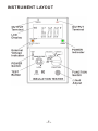
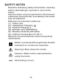
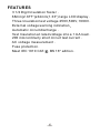
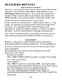
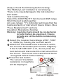
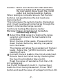
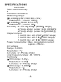
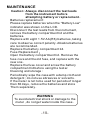
Instruction Manual
Model 308A Digital Insulation & Continuity Meter
INDEX
PAGE
INSTRUMENT LAYOUT...............................
1
INTRODUCTION........................................
2
SAFETY NOTES.........................................
3
FEATURES................................................
4
MEASURING METHODS.............................
5-7
SPECIFICATIONS......................................
8-9
MAINTENANCE..........................................
10
LIMITED ONE-YEAR WARRANTY................
11
SERVICE INFORMATION............................
12
INSTRUMENT LAYOUT
-1-
INTRODUCTION
NOTE
This meter has been designed and tested according
to IEC publication 348 , safety
requirements for electronic measuring apparatus ,
IEC-1010 (EN 61010) and other safety standards .
Follow all warnings to ensure safe operation .
WARNING
READ "SAFETY NOTES" ( NEXT PAGE )
BEFORE USING THE METER .
-2-
SAFETY NOTES
— Read the following safety information carefully
before attempting to operate or service the
meter .
— Use the meter only as specified in this manual ;
otherwise the protection provided by the meter
may be impaired .
— Rated environmental conditions :
(1). Indoor use .
(2). Installation Category
.
(3). Pollution Degree 2 .
(4). Altitude up to 2000 Meter .
(5). Relative Humidity 80% Max.
(6). Ambient Temperature 0~40 °C
— Observe the international electrical symbols
listed below .
Meter is protected throughout by double
insulation or reinforced insulation .
Warning ! Risk of electric shock .
Caution ! Refer to this manual before
using the meter .
Alternating current .
-3-
FEATURES
— 3 1/2 Digit Insulation Tester .
— 68mm(2.677")x34mm(1.33") large LCD display .
— Three Insulation test voltage 250V,500V,1000V .
— External voltage warning indication
— Automatic circuit discharge .
— Test Insulation at rated voltage into a 1 mA load .
— 200 mA continuity short circuit test current .
— AC voltage measurement .
— Fuse protection .
— Meet IEC 1010 CAT. , BS 16 th edition .
-4-
MEASURING METHODS
Operation caution
Observe all safety precautions when the FUNCTION
switch is set to either the 200M (250,500V) or the
2000M (1000V) position . Connect the meter test
leads to the circuit under test before operating the
TEST switch . Do not touch the clip ends of the test
leads when the TEST switch is pressed .
Some electrical equipment , especially cables , may
retain an electrical charge when disconnected from
the line . It is good practice to discharge such
equipment with grounding straps , or other suitable
devices , before touching or making connections .
The meter automatically discharge the test circuits
when the spring loaded TEST switch is released .
Important
Remove all power to the circuit under test when
making resistance measurements . If any voltage is
present in the test circuit the red on the meter scale
plate will light .
Immediately disconnect test leads and turn off
power to test circuit .
— Function switch :
The FUNCTION switch is used to select the range ,
or function desired .
— Test switch :
The TEST switch is normally OFF , spring loaded ,
momentary action switch which "turn on" the meter.
the momentary action is a safety feature .
The test voltage generated by the meter is
automatically discharged when the TEST switch is
released .
-5-
— Always check the following before testing :
The "Battery Low" indicator is not showing.
There is no visual damage to the instrument or
test leads.
— Test Lead Continuity:
Select the CONTINUITY function and 20W range.
Short the test leads together.
An over-range ( "1" ) indication will mean that the
leads are faulty or instrument fuse is blown. (See
"Fuse Replacement" section)
— Insulation Resistance Testing:
Warning: Insulation tests should be conducted on
circuits that are de-energised . Ensure
circuits are not live before commencing
testing.
Select the required test voltage (250V , 500V
or 1000V) by rotating the function switch .
Attach the test leads to the instrument and to
the circuit to be tested (see connect diagram) .
If the "LIVE CIRCUIT" is lit , do not press the
test button and disconnect the instrument from
the circuit . The circuit is live and should be de
-energised before further testing .
Press the test button .
The value of insulation
resistance in megohms
will be displayed .
Connect Diagram
-6-
Caution: Never turn the function dial whilst the
button is depressed. This may damage
the instrument. Never touch the circuit
under test during insulation testing.
When testing is complete ensure that the test
buttonis released before the test leads are
disconnected .
This is because the system may be charged up
and it must be allowed to discharge through the
tester's Internal discharge resistor .
— Continuity testing (Resistance tests) :
Warning: Ensure circuit are not live before
commencing testing .
Select the 20 range by rotating the range
selector and connect the test leads to the
instrument .
Short the tips of the leads . Press and hold
down the test button by twisting it a quarter
turn clockwise .
The display will show the resistance of the test
leads . Adjust the
ZERO control to set the
reading of zero .
Connect the test leads to the circuit under test .
Ensure the circuit is not live by checking that
the live circuit indicator does not lit .
Read the value of resistance from the LCD .
— AC voltage test :
Set FUNCTION switch to ACV . Connect test
leads to circuit being measured , Press TEST
button and read the value of voltage form the LCD.
-7-
SPECIFICATIONS
test leads.
— Test Lead Continuity:
S
— Insulation resistance
Measuring range :
0-200M (250V,500V DC ±10%)
Resolution : 1 count / 100K
0-2000M (1000V DC ±10%)
Resolution : 1 count / 1M
Accuracy : ±1.5% rdg. ±5dgt. (200M range
±3%rdg. ±3dgt. (under 1G / 2000M
±5%rdg. ±5dgt. (under 2G 2000M
Output current :
1 mA DC min. at 0.25 M (250V range)
1 mA DC min. at 0.5 M (500V range)
1 mA DC min. at 1 M (1000V range)
Power consumption : Max. consumption current
approx. 250mA .
— AC voltage
Range : 0-600V.
Resolution : 1V.
Accuracy : ±1.5%rdg. ±3dgt.
Line frequency range : 40 -120 Hz .
— Continuity
Ohm range : 0-20
Resolution : 0.01
Accuracy : ±1.5%rdg. ±5dgt.
Ohm range : 0-2000
Resolution : 1
Accuracy : ±1.5%rdg. ±3dgt.
-8-
—
—
—
—
Open circuit terminal voltage : 4 V DC min.
Short circuit terminal current : 210 mA DC min.
Power consumption: Max. consumption current
approximately 160mA
Buzzer sound below : under 10 (on 20 range)
Withstand :Meet IEC-1010 safety requirements
Category
.
Dimension :170 165 92 mm 6.7 6.5 3.6 inch
with housing front cover
Weight : 1.04 kg ( battery included )
Standard Accessories :
Batteries 1.5V , size AA (R6)
8 pieces
Test Leads
1 pair
Fuse 0.5A , 250V
1 piece
Instruction Manual
1 vol.
-9-
MAINTENANCE
Caution: Always disconnect the test leads
from the instrument before
attempting battery or replacement .
— Batteries replacement :
Please replace batteries when the "Battery Low"
indicator was shown on the LCD.
Disconnect the test leads from the instrument,
remove the battery compartment lid and the
batteries.
Replace with eight 1.5V AA (R6) batteries, taking
care to observe correct polarity. Alkaline batteries
are recommended.
Replace the battery compartment lid.
— Fuse Replacement
Open the battery compartment lid. Remove the
fuse cove and the old fuse, and replace with the
new one.
Replace the fuse cover and screw the battery
compartment lid before using the tester.
— Cleaning and storage :
Periodically wipe the case with a damp cloth and
detergent ; do not use abrasives or solvents .
If the meter is not to be used for periods of longer
than 60 days, remove the batteries and store
Them separately .
WARNING
To avoid electrical shock or damage to the
meter , do not get water inside the case .
-10-
Limited One-year Warranty
B&K Precision warrants to the original purchaser that its
products and the component parts thereof, will be free
from defects in workmanship and materials for a period of
one year from date of purchase from an authorized B&K
Precision distributor.
B&K Precision will, without charge, repair or replace, at its
option, defective product or component parts. Returned
product must be accompanied by proof of the purchase
date in the form of a sales receipt.
To obtain warranty coverage in the U.S.A., this product
must be registered by completing the warranty registration
form on www.bkprecision.com within fifteen (15) days of
purchase.
Exclusions: This warranty does not apply in the event
of misuse or abuse of the product or as a result of
unauthorized alterations or repairs. The warranty is
void if the serial number is altered, defaced or removed.
B&K Precision shall not be liable for any consequential
damages, including without limitation damages resulting
from loss of use. Some states do not allow limitations of
incidental or consequential damages. So the above
limitation or exclusion may not apply to you.
This warranty gives you specific rights and you may have
other rights, which vary from state-to-state.
B&K Precision
22820 Savi Ranch Parkway
Yorba Linda, CA 92887
www.bkprecision.com
714-921-9095
-11-
Service Information
Warranty Service: Please return the product in the
original packaging with proof of purchase to the
address below. Clearly state in writing the performance
problem and return any leads, probes, connectors and
accessories that you are using with the device.
Non-Warranty Service: Return the product in the
original packaging to the address below. Clearly state
in writing the performance problem and return any
leads, probes, connectors and accessories that you
are using with the device. Customers not on open
account must include payment in the form of a money
order or credit card. For the most current repair
charges please visit www.bkprecision.com and click on
"service/repair".
Return all merchandise to B&K Precision with pre-paid
shipping. The flat-rate repair charge for Non-Warranty
Service does not include return shipping. Return
shipping to locations in North American is included for
Warranty Service only. For overnight shipments and
non-North American shipping fees please contact B&K
Precision.
B&K Precision
22820 Savi Ranch Parkway
Yorba Linda, CA 92887
www.bkprecision.com
714-921-9095
Include with the returned instrument your complete
return shipping address, contact name, phone
-12-
B&K Precision
22820 Savi Ranch Parkway
Yorba Linda, CA 92887
U.S.A.
www.bkprecision.com
Printed in Taiwan / Ver. 1.0/0307
© 2007 B&K Precision Corporation