1
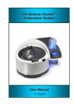
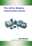
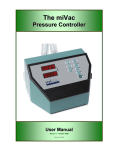
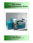
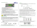
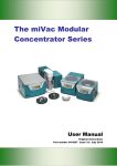
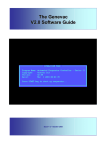
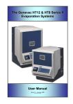
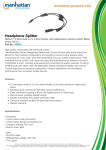
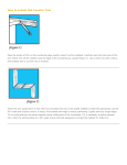
EZ-2
Belt Tensioning
Part Number: 04-4500
Issue 1 – January 2004
EZ-2 Belt Tensioning
1.
Introduction
This procedure provides guidance in the tensioning of:
EZ-2 Drive Belts.
2.
Safety and Maintenance Notes
Ensure that safety and maintenance notes are complied with throughout this work instruction.
3.
Special tools and equipment
Description
Belt tensioning tool
Rubber band (152 x 3)
Allen Key 6mm
Open Ended Spanner 10mm
Part number
04-3658
04-4499
Quantity
1
Bag
1
1
ENSURE THAT EVAPORATOR IS ISOLATED FROM MAINS POWER SUPPLY.
ANY MAINTENANCE OR REPAIR OF THIS PRODUCT SHALL BE CARRIED OUT BY
GENEVAC PERSONNEL (OR APPROVED REPRESENTATIVES OF GENEVAC) USING
ONLY APPROVED SPARE PARTS.
4.
Preparation
4.1
Ensure that you have the special tools and equipment available as listed at paragraph 3.
Fig 1 - Belt Tensioning Tool (04-3658)
4.2
Ensure that you follow this procedure in conjunction with Section 3 Chapter 2 of the EZ-2 User Manual.
04-4500 Issue 1 – January 2004
Page 1
EZ-2 Belt Tensioning
5.
Checking Belt Tension
5.1
Rotate the pulleys so that the tightest part of the belt is at the measurement point. This is done by feel
only. Mark this point on the belt using marker pen or chalk.
5.2
Place the supplied rubber band (nominally 160mm long, 1mm thick, 6mm wide max) over plain part of
pulleys. Ensure band is sitting flat and not on either the groove or the edge. See Fig 2.
Fig 2 – Drive Belt and Elastic Band
5.3
Slide the tensioning tool (tool) between the belt and the elastic band at a position along the belt
immediately adjacent to the tapped holes. Ensure min. gap between the tool shaft and the base of the
system. See Fig 3.
Fig 3 – Tool in position, pressure being applied.
04-4500 Issue 1 – January 2004
Page 2
EZ-2 Belt Tensioning
5.4
Hold the tool such that a steady load can be applied to the rubber-covered end.
5.5
Compress the tool so that the small spindle is just touching the elastic band.
5.6
The yellow end of the tool body should meet the mark of 3.5kg (Do not hold the body of the tool). See
Fig 4.
Fig 4 – Read Gauge
5.7
Adjust the belt tension until the tension is correct.
5.8
To adjust the belt tension loosen the four motor screws and the lock nut on the tensioner screw.
BELT TENSION
MEASUREMENT POINTS
DRIVE BELT
BELT TENSIONER
DRIVE MOTOR
SECURING SCREWS
Fig 5 – Drive Belt
5.9
Adjust the belt tension screw (clockwise will tighten the belt) ¼ turn at a time.
5.10 Re-tighten the 4 rotor screws.
04-4500 Issue 1 – January 2004
Page 3
EZ-2 Belt Tensioning
5.11 Re-check the tension and repeat adjustment until the correct tension is achieved.
5.12 Rotate belt at least one whole rotation and repeat Operations 4 and 5 so the 3.5kg mark becomes an
average.
5.13 Lock the tension screw nut.
5.14 Re-check the 4 rotor screws.
5.15 Remove the elastic band.
5.16 Replace the cover.
04-4500 Issue 1 – January 2004
Page 4