1
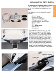
In addition to the hardware kit that you received
with the QBOT, you will need the hardware
in this kit to complete the installation on your
frame.
The hardware kit for the Grace GMQ Pro
includes:
(4)
(4)
(2)
(1)
(1)
(1)
(1)
(1)
(1)
¼-20 x 2” screws
Aluminum spacers
X-axis brackets
X-axis drive wire 6 ft. length
X-axis drive wire 12 ft. length
Y-axis drive wire
¼-20 X 1” screw
¼-20 nut
¼” fender washer
Using two of the ¼ X 2” long screws and two of
the aluminum spacers, attach a drive bracket to
the rear of the lower carriage. This procedure
is similar to what is shown on page 2 of your
QBOT user manual. Look closely at the pictures
below to see where to place the aluminum
spacers. Tighten the screws securely.
GRACE GMQ PRO
INSTALLING THE DRIVE SYSTEM
GRACE GMQ PRO
INSTALLING THE DRIVE SYSTEM
Install the two X-axis brackets that came with this
hardware kit on the lower carriage as shown. The
bracket labeled with an ‘L’ mounts to the rear left-hand
side of the lower carriage. The bracket labeled with
an ‘R’ mounts to the front right hand side of the lower
carriage. Simply loosen the screw on the carriage
and slip the bracket under the head of the screw. It is
important that they are attached at the angle shown in
the pictures. This will ensure that the drive wire will be
installed level.
The front attachment looks like the picture
to the left. The drive wire is shown installed
and the tensioner has been adjusted to
the correct tension using the tensioning
template found at the back of your QBOT
manual.
Aluminum spacers
Using the remaining ¼-20 X 2” screws and aluminum
spacers, attach a drive bracket to the upper carriage
as shown in the picture to the right. Note the
location of the aluminum spacers. Tighten the screws
securely.
You will install the drive wire in the next step.
The drive wire is installed by hooking one end of the wire
to the rear wire bracket and winding twice (2X) around the
drive wheel. Looking at the picture to the right, note how
the drive wire is wrapped around the wheel so that it is on
the bottom side of the drive wheel. Wrapping the wire
the wrong way (off the top side) will cause the carriage to
go backwards.
Hook the eyelet at the other end of the wire on one side
of the tensioner as shown in the picture below. Hook the
other end to bracket as shown and tighten the tensioner
until the tension in the wire falls in the proper range
shown on the tensioning template. See page 5 of the User
Manual for reference.
GRACE GMQ PRO
INSTALLING THE DRIVE SYSTEM
GRACE GMQ PRO
INSTALLING THE DRIVE SYSTEM
Attach the other set of X-axis brackets
to your frame on either end as shown
in the photos to the right. Note the
orientation of the brackets. Simply loosen
the screw on the frame and slide the
bracket underneath the head of the screw.
Tighten securely.
Bottom edge level
Attach one end of the drive wire to the X-axis
bracket as shown in the top photo. Wrap the wire
around the drive wheel twice and ensure that you
start at the TOP of the wheel as shown in the photo
to the left. Attach the other end of the wire to the
tensioner as shown in the photo above. Finally
attach the other end of the tensioner to the X-axis
bracket as shown above. Use the tensioning template in the back of the User Manual to set the
proper tension in the wire.
Using the ¼-20 X 1” screw, nut, and fender washer, attach the QBOT mounting bracket to the upper carriage handle assembly. Tighten securely.
Congratulations!
You are now ready to make the connections. Follow the instructions in your User Manual starting
on page 15.
GRACE GMQ PRO
INSTALLING THE DRIVE SYSTEM