Download User`s manual KNX MultiLight (ML-K)
Transcript
User’s manual KNX MultiLight (ML-K) Article number: 44001 Picture: KNX MultiLight User Panel function Innovation & Technology AS function Innovation & Technology AS -2- Manual – KNX MultiLight Art.nr 44001 Doc.no. D-TS-ML-K-005-A Table of content 1 APPLICATION FOR THE KNX MULTILIGHT ROOM CONTROLLER ................ 4 2 INTRODUCTION ............................................................................................ 4 3 MULTILIGHT START-UP AND GENERAL FUNCTIONS ................................... 6 4 GENERAL FUNCTIONS AND USER PANEL ..................................................... 8 5 MOVEMENT AND LUX LEVEL DETECTION ..................................................... 9 5.1 MOVEMENT SENSOR ......................................................................................................................... 9 5.1.1 Master function ”Movement General” ........................................................................... 10 5.1.2 Slave function ”Movement General” ............................................................................. 10 5.1.3 Cyclic sending ................................................................................................................... 10 5.2 LUX SENSOR ................................................................................................................................. 11 5.2.1 Parameters ....................................................................................................................... 11 5.2.2 LUX calibration ................................................................................................................. 11 5.3 BLOCK DIAGRAM ............................................................................................................................ 12 5.4 OBJECT LIST .................................................................................................................................. 13 6 THERMOSTAT .............................................................................................. 14 6.1 REGULATOR FUNCTIONALITY .......................................................................................................... 14 6.2 OPERATIONAL MODES .................................................................................................................... 14 6.3 PARAMETERS ................................................................................................................................ 15 6.3.1 Comfort mode ................................................................................................................. 15 6.3.2 Standby mode ................................................................................................................. 16 6.3.3 Night mode ...................................................................................................................... 16 6.3.4 Frost/Heat protection ..................................................................................................... 16 6.3.5 Basic heating and cooling stage ................................................................................... 17 6.3.6 Additional heating and cooling stage ........................................................................... 17 6.4 LOCAL TEMPERATURE ADJUSTMENT ................................................................................................. 18 6.5 REGULATOR FUNCTION .................................................................................................................. 19 6.6 PI REGULATOR ............................................................................................................................. 20 6.7 OBJECT LIST ................................................................................................................................. 21 7 SWITCH ACTUATOR .................................................................................... 24 7.1 PARAMETER ................................................................................................................................... 24 7.1.1 Staircase function ............................................................................................................ 24 7.1.2 ON/OFF Delay function ................................................................................................... 25 7.1.3 Logic AND/OR .................................................................................................................. 25 7.1.4 Force operation ................................................................................................................ 25 7.2 INITIAL START-UP AND POWER FAILURE CONSIDERATIONS ................................................................. 25 7.3 BLOCK DIAGRAM ............................................................................................................................ 25 7.4 OBJECT LIST .................................................................................................................................. 26 8 BINARY INPUTS .......................................................................................... 27 8.1 PARAMETER ................................................................................................................................... 27 8.1.1 Switch ................................................................................................................................ 27 8.1.2 Dimming ............................................................................................................................ 27 8.1.3 Shutter .............................................................................................................................. 28 8.2 BLOCK DIAGRAM ............................................................................................................................ 28 8.3 OBJECT LIST .................................................................................................................................. 29 9 MECHANICAL DIMENSIONS ........................................................................ 31 9.1 DETECTION AREA MOVEMENT SENSOR (ML-M) ............................................................................... 32 9.2 CONNECTOR PINOUT ..................................................................................................................... 32 10 WIRING DIAGRAM .................................................................................... 33 11 TECHNICAL DATA ...................................................................................... 34 function Innovation & Technology AS -3- Manual – KNX MultiLight Art.nr 44001 Doc.no. D-TS-ML-K-005-A 1 Application for the KNX MultiLight room controller KNX MultiLight is a three part room controller designed to be pre-fabricated into suspended luminaires. The KNX MultiLight node, the movement detector and the user panel will control lighting, climate and shutters in both closed and open plan offices. The main functions of the KNX MultiLight are: Controlling heating and cooling Temperature sensing User’s panel for manual control Relay output for light control Movement and LUX sensor For programming and configuration see chapters 3 to 8. For wiring and installation instructions see chapter 10. For technical see chapter 11. 2 Introduction KNX MultiLight is designed to be an efficient room controller system for office, hotels and other commercial buildings where suspended luminaire are used. The core of the KNX MultiLight is a demand controlled two-step temperature regulator for separate coolingand heating control. The functionality of the product can be configured and connected to the rest of the KNX automation system by using the ETS Tools Software (see www.knx.org) Example 1 – Heating regulator: The KNX MultiLight is configured as a two-step heating regulator. The regulator has one temperature set-point for a room that is occupied and another temperature set-point for a room that is vacant. Let’s say the temperature set-point for an occupied room is 22°C and the set-point for the vacant room is set to 19°C. The movement detector mounted in the suspended luminaire will detect a person walking into the room. The set-point will be raised from 19°C in standby mode (vacant) to 22°C in comfort mode (occupied). Example 2 – Lighting: The KNX MultiLight can turn on and off the luminaire. So, when a person walks into the room and the temperature set-point is changed from standby to comfort mode, the light will also be turned on. The light can remain off if the lux level in the room is so high that the light from the luminaire is not needed. function Innovation & Technology AS -4- Manual – KNX MultiLight Art.nr 44001 Doc.no. D-TS-ML-K-005-A Example 3 – Ventilation: The KNX MultiLight can control ventilation for the office space based on the movement detector and the temperature regulator. The ventilation can be reduced to a minimum when the room is vacant and the controller is in standby mode. The ventilation system will be asked to increase the ventilation when a person enters the room. The ventilation system will usually have a cooling effect for the room because of lower air temperature in the supplied air. The cooling regulator of the KNX MultiLight can trigger the need for extra ventilation based the room temperature. Example 4 – User control: The KNX MultiLight will usually control the climate and lighting automatically. Occupants may want to take control over their own environment and change lighting, temperature and shutters manually. The KNX MultiLight can be fitted with a user panel that will replace the luminaire pull cord. The panel can give the user temperature control, control of shutters and lighting control. The temperature setpoint can be adjusted -3°C to +3°C from the user panel (see Figure 1). Figure 1 - KNX MultiLight user panel function Innovation & Technology AS -5- Manual – KNX MultiLight Art.nr 44001 Doc.no. D-TS-ML-K-005-A 3 MultiLight start-up and general functions KNX MultiLight can be configured by using the ETS Tools Software. The product database file for KNX MultiLight can be downloaded from http://www.function.no/MultiLight. Documentation for the parameters, objects and example configurations can be found in the chapters below. The MultiLight controller can be set in learn-mode by pressing the learning-mode switch on the KNX node or by pressing the learn button on the movement detector. The locations of the buttons are shown with red circles in Figure 2. Use a small circular object like a paper clip or a bare KNX copper wire to reach the programming button on the movement detector. Figure 2 - Learn mode buttons The red programming LED on the KNX node and inside the lens of the movement detector will be lit when the KNX MultiLight is in learn mode. The programming LED will blink when the MultiLight is not programmed (un-programmed node). The node will check communication with movement detector and panel. If communication has failed the object “Device self-test status” will be set to “1”. When the error situation is cleared the “Device self-test status” object changes its value to 0. The startup procedure for a unit that has not been programmed with ETS includes switching on the relay and showing motion detection with the red LED. This ensures that not programmed units will turn on the light automatically. function Innovation & Technology AS -6- Manual – KNX MultiLight Art.nr 44001 Doc.no. D-TS-ML-K-005-A Note: The KNX node includes basic functionality for test and commissioning purposes that will be removed after the first ETS download: 1. The digital inputs will toggle the relay. Digital input 1 can be connected to an impuls switch for the luminaire pull cord. Pulling the cord will toggle the light on and off. 2. Detection of movement is shown by blinking the red LED inside the movement detector lens. Figure 3 – KNX MultiLight node, movement detector and user panel function Innovation & Technology AS -7- Manual – KNX MultiLight Art.nr 44001 Doc.no. D-TS-ML-K-005-A 4 General functions and user panel The status of the KNX MultiLight is shown by the object “Self-Test status”. For normal operational nodes this status object is low. If the movement sensor or user panel does not respond the self test status is set high. The object can be configured to be sent cyclic [1 to 24 hours]. The KNX MultiLight can be configured without a user panel, with a standard or extended user panel. The standard and extended user panel option includes a temperature sensor, buttons for local adjustment of the temperature set-point and LED indication of the local adjustment. The user panel will also show the status of the temperature regulator by showing either a red light if the temperature regulator is heating or a blue light if the temperature regulator is cooling. The extended user panel will also include up and down buttons and LED indication for manual shutter control. The temperature regulator is not available if the KNX MultiLight is configured without a user panel. The temperature sensor can be calibrated from the user panel. The calibration mode is activated if both the + and – buttons are pressed for 5 seconds or more. In this mode the temperature LED will start to blink for the calibration setting. The + and – buttons will increase or decrease the measured temperature in steps of 0.5°C. So, the measured temperature will be adjusted 1.5°C lower if the -3 LED is blinking. The adjustment has to be acknowledged by pressing both the + and – button. Table 1 - Object list for general and user panel objects ID Name Description Configuration OBJ 000 Device: Self-Test status 1 bit 1.001 CR-T OBJ 001 Panel: Shutter operation – Stop/Step OBJ 002 Panel: Shutter operation – Up/Down This object will report self test result and alive status with a "0" if everything is ok. If it sends "1" the self test has failed. The object can be set to cyclic sending by parameter. This object will be set if the communication with the movement detector or user panel has failed. This object will be visible if parameter “Activation of user panel” is set to “Extended user panel”. The object will be transmitted with a 1 or a 0 if the up or down button is pressed (short operation) This object will be visible if parameter “Activation of user panel” is set to “Extended user panel”. The object will be transmitted with a 1 or a 0 if either the up or down button is pressed (long operation). function Innovation & Technology AS -8- 1 bit 1.007 C--T 1 bit 1.008 C--T Manual – KNX MultiLight Art.nr 44001 Doc.no. D-TS-ML-K-005-A 5 Movement and LUX level detection 5.1 Movement sensor The combined movement and LUX level sensor is connected to the MultiLight KNX node through a 4-wire cable. The communication object for the movement sensor, object 003 "Movement General", has the following parameter settings: Figure 4 - Movement sensor parameter window 1. Recovery time for detection from 1 to 255 minutes. The recovery time specifies the time between the last detected movement and when the object is set low. 2. Action for start of detection can be ”ON” or “no reaction”. 3. Cyclic sending On commands of "Movement General" can be enabled or disabled. The cycle time can be between 1 and 255 minutes. 0 disable the function. 4. Action for end of detection can be ”OFF” or “no reaction”. 5. Separate Movement Local object The movement detector can be configured with an additional communication object named “Movement Local”. This object can have the following functionality: a. Semi-automatic: "Movement Local" object is not transmitted at start of detection, but will transmitt a ”0” for end of detection. The object can be used as a turn off function. b. Full automatic: "Movement Local" object is transmitted both at start of detection and end of detection. The object can be used to both turn on and off a function. 6. (Only visble if “Full automatic” is enabled) Light dependent full automatic: "Movement Local" object can turn on and off a function base on both movement and the lux threshold switch (see chapter below). function Innovation & Technology AS -9- Manual – KNX MultiLight Art.nr 44001 Doc.no. D-TS-ML-K-005-A 7. PIR sensitivity can be adjusted from 20 to 100, where 20 is the highest sensitivity. This parameter is default set to 40 and should not be set lower than this value without testing for false detection. 5.1.1 Master function ”Movement General” The “Movement General” can be re-trigged from another sensor like switches and movement detectors. It is necessary to set the “Write” flag in the object 3 “Movement General” to make the object re-triggable. Se Figure 5. Figure 5 - Object flags for re-triggable "Movement General" object It is not possible to re-trigg the “Movement Local” by object. This object can only be re-trigged by the local movement detector. 5.1.2 Slave function ”Movement General” The “Movement General” could be configured with “Slave” functionality. The slave functionality can be enabled by setting the recovery time and the cyclic sending time to a lower value than the Master (master detector recovery time or staircase timer). The reaction at the end of detection must be set to “No reaction”. 5.1.3 Cyclic sending If the value of cyclic sending is lower than the recovery time, the sensor will not send any cyclic ON telegrams. If the two values are the same, the sensor sends one cyclic sending right before the recovery time elapses. The cyclic sending time will not be affected by a re-trigged recovery time. function Innovation & Technology AS - 10 - Manual – KNX MultiLight Art.nr 44001 Doc.no. D-TS-ML-K-005-A 5.2 LUX sensor 5.2.1 Parameters The lux sensor has two communication objects, one for the LUX value (Current Value) and a threshold switch (Lux threshold switch). The object, “Lux threshold switch", will be high or low based on the LUX value and the parameters below. Figure 6 - Lux sensor parameter window 1. High threshold value: If the Lux value goes above this value the "Lux threshold switch" will be set low or no action (depending on the parameter “Action above high threshold value”). 2. Hystereses for lower value: “High threshold value” – “hysteresis for lower value” will give the lower limit for the ”Lux threshold switch”. If the current lux value is below this value, the Lux threshold switch is set high or no action (depending on the parameter “Action below low threshold value”) 3. Time delay can be specified both for turning on and off the lux threshold switch. The time delay can be between 1 and 255 seconds. The value “0” will disable the time delay. 4. Cyclic sending of the lux threshold switch can be activated with a cycle time between 1 and 255 minutes. 5.2.2 LUX calibration The lux level object, “Lux Sensor: Current value (lux)”, can be calibrated by writing to the object. The raw lux value will be subtracted from the written value and stored permanently in EEPROM/flash. Both raw values and the resulting calibrated values are shown in Figure 7. The pink line is the raw value (V) from the sensor, the blue line is the wanted value (W) set by the user. The calibration factor is: C=1-(V-W/V) If the raw value V=1000, and the object is updated with 800, then the calibration factor will be: c=1-(1000-800)/1000=0.8. See the graph in Figure 7. The formula for calculating the lux is: Lux=c*V function Innovation & Technology AS - 11 - Manual – KNX MultiLight Art.nr 44001 Doc.no. D-TS-ML-K-005-A Figure 7 - Raw and calibrated lux values The calibration factor is set to 1 and the raw value is used if “0” is written to the “Current value (lux)” object. The object should be set to 0 to clear the current calibration before re-calibrating the lux level. The lux level calibration is limited to 2 times the raw lux level, so the calibration is limited to 2000 if the raw lux level is 1000. 5.3 Block diagram Figure 8 - Block diagram of movement and lux sensor function Innovation & Technology AS - 12 - Manual – KNX MultiLight Art.nr 44001 Doc.no. D-TS-ML-K-005-A 5.4 Object list Table 2 - Object list for the Movement Sensor ID Name Description Configuration OBJ 003 Movement: General 1 bit 1.001 C - (W) T OBJ 004 Movement: Local When the movement detector detects movement Obj. 003 either sends a “1” or “No reaction” depending on parameter “Reaction at start of detection”. At the end of detection (when the “Recovery time” has elapsed) the object will be transmitted either with a “0” or “No reaction”. The object can be set to cyclic sending depending on parameter “Cyclic sending”. This object can be configured by parameter “Separate Movement Local” to either “Disabled”, “Semi automatic” or “Full automatic”. In Semi automatic mode it will only transmit at the end of detection. In “Full automatic” the object will transmit both at the start of detection and at the end of detection. This object is not cyclic. The object can also be dependent on the “Lux Threshold Switch” 1 bit 1.001 C--T Table 3 - Object list for the LUX Sensor ID Name Description Configuration OBJ 005 Lux Sensor: Current value (lux) 2 byte 9.004 CRW- OBJ 006 Lux Sensor: Lux threshold switch Writing a LUX value to this obj. will calibrate the value from the sensor. The calibration will NOT be overwritten when new ETS software is downloaded. The calibration and the lux value written to Obj. 005 will be stored permanently in EEPROM/flash. The object transmits a 1, 0 or no action depending on the Current value (lux) and the threshold parameters and the chosen action from parameter. The object can be sent cyclic. It is possible to activate turn-on and/or turn-off delay via parameters. function Innovation & Technology AS - 13 - 1 bit 1.001 C--T Manual – KNX MultiLight Art.nr 44001 Doc.no. D-TS-ML-K-005-A 6 Thermostat 6.1 Regulator functionality The thermostat can control both heating- and cooling systems and will automatically switch between heating and cooling mode. The regulator outputs can be configured either as ON/OFF control or continuous (0-100%) based on a PI regulator. The KNX MultiLight has to be configured with a user panel with temperature sensor to have temperature regulator functionality. Regulator capability: Four modes of operation: comfort, standby, night and frost/heat protection On/off or 0-100% control for heating and cooling system Combined heating- and cooling regulator with automatic switch-over Additional heating or cooling stage with on/off control Automatic transmission of the regulator outputs on change or cyclic every 40. Minutes. Room temperature measurement from the user panel The temperature sensor can be calibrated (+/- 12.6K) in steps of 0.1 K with ETS parameter The temperature sensor can be internal calibrated (+/-1.5K) from the user panel The actual temperature and the set-point temperature can be sent to the bus on change or cyclically Set-point values: The base temperature set-point is defined in parameter (“Base setpoint in ºC”) and is shown by object “Thermostat – Base setpoint”. This object can also be configured for write access (selectable to be stored in permanent memory or not) The working regulator set-point is shown by the object “Thermostat – Actual setpoint”. The base setpoint is only settable to whole degrees (eg. 21 or 22 °C) Parameters for heating and cooling temperature set-points for standby and night mode Set-points for the additional heating/cooling stage are derived from the values from the basic stage with an additional stage offset Setpoint value shifting (local adjustment +/-3K) by local operation on the user panel or by object. The step size is 0.5K The reduced or increased temperatures for standby and night mode are settable in steps of 0.1K Frost/heat protection: frost protection set to 10 ºC (not adjustable) and heat protection set to 35 ºC (not adjustable) 6.2 Operational modes The KNX MultiLight has 4 operational modes; Comfort, Stand-by, Night and Frost/heat protection. The active mode is selected based on the three 1.bit objects "Comfort Mode", "Night Mode" and "Frost/heat protect". The table below shows which mode is active based on the status of these three objects (X = don’t care). Table 4 - Regulator modes Active mode/object Comfort value Mode Standby 0 Night Mode 0 Comfort Mode 1 Frost/heat protect X function Innovation & Technology AS - 14 - Night Mode 0 1 X X Frost/ heat 0 0 0 1 Manual – KNX MultiLight Art.nr 44001 Doc.no. D-TS-ML-K-005-A 6.3 Parameters 6.3.1 Comfort mode The thermostat is using the “Base setpoint in ºC” as the regulator set-point for the heating regulator in comfort mode. The heating regulator starts to heat if the actual temperature falls below the base setpoint minus the parameter value for “Low hysteresis in 0.1K". The heating regulator will turn off the heat when the actual temperature rises above the base setpoint. The regulator will turn off the heat at 21.0 ºC with the parameter settings shown in Figure 9 The cooling system will turn on at the temperature "Base setpoint in ºC" + "Deadzone between heating and cooling in 0.1K" + "High hysteresis in 0.1K". The cooling system will be turned off when the temperature falls below the base set-point + deadzone. The cooling system will be turned off at 21.0 + 2.0 = 23ºC with the parameter settings shown Figure 9. Figure 9 - Thermostat settings It is the value from the object "Actual setpoint" that the regulator uses as the temperature set-point. The “Actual setpoint” will change depending on the “Base setpoint”, the active mode, if the regulator is in heating- or cooling mode and the local temperature adjustment. function Innovation & Technology AS - 15 - Manual – KNX MultiLight Art.nr 44001 Doc.no. D-TS-ML-K-005-A 6.3.2 Standby mode The regulator goes to standby mode if the three communication objects "Comfort Mode", "Night Mode" and "Frost/heat protect" are low. The "Actual setpoint" in this mode will be set to "Base setpoint" + "Reduced Heating in standby mode". The "Actual setpoint" is set to: 21ºC + (-1.0ºC) = 20ºC for the parameter settings shown in Figure 9. For the cooling system in standby mode the "Actual setpoint" is set 1 degree higher than in comfort mode: 21ºC + 2ºC + 1ºC = 24ºC The user panel LED indication for the local temperature adjustment will be turned off when the regulator goes into standby mode. The LED indication for the active heating- and cooling system will still be active. 6.3.3 Night mode The regulator will go to night mode if only the “Night Mode” object is set high. The temperature setpoint for the heating and cooling systems will change according to the parameters "Reduced Heating in Night mode" and "Increased cooling in Night mode". For the heating system the “Actual setpoint” is set to: 21ºC + (-3.0ºC) = 18ºC with the parameters shown in Figure 9. For the cooling system the "Actual setpoint" will be: 21ºC + 2ºC + 3ºC = 26ºC The user panel LED indication for the local temperature adjustment will be turned off when the regulator goes into night mode. The LED indication for the active heating- and cooling system will still be active. 6.3.4 Frost/Heat protection The Frost/Heat protection regulator mode will set fixed temperature setpoints for the heating and cooling regulators. The heating system is turned on if the temperature falls below 10ºC – 0.5ºC hysteresis. The heating system is turned off if the temperature goes above 10ºC. The cooling system will turn on if the temperature goes above 35ºC + 0.5ºC hysteresis and will turn off again when the temperature goes below 35ºC. The user panel LED indication for the local temperature adjustment will be turned off when the regulator goes into Frost/heat protection mode. The LED indication for the heating- and cooling system alternates between heating and cooling every second. function Innovation & Technology AS - 16 - Manual – KNX MultiLight Art.nr 44001 Doc.no. D-TS-ML-K-005-A 6.3.5 Basic heating and cooling stage See the description of the different regulator modes in chapters 6.3.1 to 6.3.4. 6.3.6 Additional heating and cooling stage The KNX MultiLight can control an additional heating and/or cooling system with ON/OFF control. The temperature limits for the additional heating- and cooling systems can be defined by parameters, see Figure 10 and Figure 11. The additional heating stage will be turned on if the room temperature has dropped 2ºC below the parameter settings in the thermostat parameter window, see Figure 9. The hysteresis for the additional heating stage is fixed to +0.5ºC. The additional heating stage will turn on if the temperature falls below 21ºC - 2.0ºC = 19ºC and turn off at 21ºC - 2.0ºC + 0.5ºC = 19.5ºC in comfort mode according to the parameter settings shown in Figure 9 and Figure 10. Figure 10 - Heating parameter windows Figure 11 - Cooling parameter windows The additional cooling stage will be turned on bases on the stage offset from basic to additional stage, see Figure 11. The additional stage cooling will turn on if the temperature rises above 23ºC + 2.0ºC = 25ºC for comfort mode (see parameters Figure 9). The additional stage will turn off at 23ºC + 2.0ºC - 0.5ºC = 24.5ºC function Innovation & Technology AS - 17 - Manual – KNX MultiLight Art.nr 44001 Doc.no. D-TS-ML-K-005-A 6.4 Local temperature adjustment The temperature setpoint can be adjusted both by the communication object “Local adjustment of temperature" (obj. 011) and by the user panel. The local adjustment of temperature object can adjust the actual temperature setpoint by +/-10ºC. The user panel temperature adjustment can maximum be +/-3ºC. The adjustment done on the panel will update the local adjustment of temperature communication object. The heating system will be turn on at 20.5ºC - 3ºC = 17.5ºC and off at 18.0ºC in comfort mode with the parameters shown in Figure 9. The cooling system will be turned on at 21ºC - 3ºC + 2ºC + 0.5ºC = 20.5ºC and Off if the temperature drops below 20.0ºC. The temperature sensor includes a filtering algorithm that will eliminate temperature rise after the user panel has been touched. The temperature measurement will remain unchanged for 3 to 8 minutes after the buttons on the user panel has been operated. It is possible to limit the temperature adjustment up or down, for example to +3 to -1C, +1.5C to -0.5C and +0.5 to -0C. The LED indicating +3 to -3 on the user panel will still show the full scale, so the user will not notice the limitation. If the panel is removed, all regulator outputs will be set to “0” one time, and the actual temperature is send 0ºC. The “Self test” object will indicate the error and will be transmitted as “1”. function Innovation & Technology AS - 18 - Manual – KNX MultiLight Art.nr 44001 Doc.no. D-TS-ML-K-005-A 6.5 Regulator function Figure 12 - Asymmetric regulator functionality function Innovation & Technology AS - 19 - Manual – KNX MultiLight Art.nr 44001 Doc.no. D-TS-ML-K-005-A 6.6 PI Regulator The KNX MultiLight thermostat can control heating and cooling systems with Pulse-WithModulation. The communication object for the PWM control value output is a 1.byte 0100% of the type DPT5.001. The control value will automatically be transmitted every 40. minutes and can also be transmitted when the value has changed a specific percentage, see Figure 13. Figure 13 - Heating PI-regulator The PI-regulator is configured with a proportional factor (Kp) and a reset time (Ti). The equation for the regulator output is shown in (3). The integration of the error for each regulator evaluation is substituted by the step number (30 second increments) multiplied with the last error function: e(n)∙n divided by the time constant, see equation (3) The proportional factor Kp : KP 1 (1) proportional _ range The error function e(n): e(n) = set_point - actual_temperature (2) The regulator output equation: u ( n) K P e( n ) function Innovation & Technology AS e( n ) n 2 TI K P e( n ) 1 - 20 - n 2 TI (3) Manual – KNX MultiLight Art.nr 44001 Doc.no. D-TS-ML-K-005-A Example: The regulator function (3) is evaluated every half minute with the parameters for Electric heating (4K/100min) and a constant error function of e(n)=set_pointactual_temp=23-21=2. The calculated output is shown in equation (4), where n is the number of half minute intervals: u ( n) 1 n (23 21) 1 4 2 100 (4) The graph for the regulator output is shown in Figure 14. The time factor, n, will be set to 0 when the error function, e(n) becomes 0 or less. The regulator output is capped to maximum 1.0, which is equivalent to 100% for the control value communication object. Regulator output (Kp=0.25, Ti=100, e(n)=2) Regulator output 1,2 1 0,8 0,6 Serie1 0,4 0,2 0 1 21 41 61 81 101 121 Time(min) Figure 14 - Regulator output for constant e(n)=2 6.7 Object list Table 5 - Object list for the Thermostat ID Name Description Configuration OBJ 007 Thermostat: Actual temperature 2 byte 9.010 CR-T OBJ 008 Thermostat: External temperature Thermostat: Base setpoint This object shows the measured room temperature (0.5K resolution). This value can also be combined with obj 008 External temperature. The actual temperature is used as the feedback to the regulator. This object will be sent automatically when the temperature has changed 0.5K or more. This object can in addition be set to cyclic sending by parameter. The external temperature can be weighed from 0 to 100% compared to object 007. OBJ 009 function Innovation & Technology AS The base setpoint is the desired temperature in comfort mode (heating). This value is the origin for all the different regulator modes. - 21 - 2 byte 9.010 C-WT 2 byte 9.010 C R (W) T Manual – KNX MultiLight Art.nr 44001 Doc.no. D-TS-ML-K-005-A 
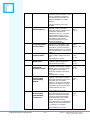
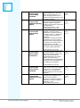
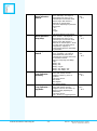
The object can be set either to read only or read/write by parameter. The updated value can either be stored in EEPROM or in volatile memory. OBJ 010 Thermostat: Actual setpoint OBJ 011 Thermostat: Local adjustment of temp offset OBJ 012 Thermostat: Comfort mode OBJ 013 Thermostat: Night mode OBJ 014 Thermostat: Frost/Heat protection mode OBJ 015 Thermostat: Control value basic heating Switch OBJ 016 Thermostat: Control value basic heating Continuous This object can be set to cyclic sending. The actual setpoint value that the regulator is using. This can be either the Comfort-, standby-,frosttemperature with the local adjustment (obj. 011). The object will transmit on change, so the setpoint will be transmitted when the regulator change mode. This object can be set to cyclic sending by parameter. The object holds the local adjustment of temperature offset. This object can be updated either from KNX or from the user panel. Maximum adjustment is +/- 3K from the user panel and +/-10K from the object. The regulator goes to ComfortMode regulator setting if this bit is set. This mode has 2. priority The regulator goes to Night-Mode regulator setting if this bit is set. This mode has 3rd priority The regulator goes to frost/heat protection mode regulator setting if this bit is set. Frost mode setpoint is permanent at 10ºC. Heat protection setpoint is 35ºC (fixed limits). This mode has 1. priority The output of the basic heating regulator. This object is set high if the actual temperature (obj. 007) is lower than obj. 010 “Actual setpoint” - hysteresis. The heating will be turned off when the actual temperature (obj. 007) goes above “Actual setpoint” (obj. 010). Cyclic sending every 40 min. The output of the PI regulator with the proportional factor and reset time from the parameter settings. The object can be automatically transmitted based on a %-value change (set by parameter). The integral part can be disabled by setting the reset time parameter to 0, resulting in a P-regulator. 2 byte 9.010 CR-T 2 byte 9.002 Flag: C - W T 1 bit 1.001 C-W1 bit 1.001 C-W1 bit 1.001 C-W- 1 bit 1.001 CR-T 1 byte 5.001 CR-T Cyclic sending every 40 min. function Innovation & Technology AS - 22 - Manual – KNX MultiLight Art.nr 44001 Doc.no. D-TS-ML-K-005-A OBJ 017 Thermostat: Control value basic heating Feedback OBJ 018 Thermostat: Control value additional heating Switch OBJ 019 Thermostat: Control value basic cooling Switch OBJ 020 Thermostat: Control value basic cooling Continuous OBJ 021 Thermostat: Control value basic cooling Feedback OBJ 022 Thermostat: Control value additional cooling Switch function Innovation & Technology AS This object gives the status of the basic heating stage. If the control value for basic heating is 1% or more this object will be set to “1” and the red heating indication in the user panel will be lit. The additional heating stage is set high if the temperature falls below the basic setpoint - parameter settings for the different modes and local adjustment. Permanent hysteresis: +0,5K. Cyclic sending every 40 min. The output of the basic cooling regulator. The target cooling temperature in comfort mode will be ”Base set point” + ”Dead zone” + regulator mode temperature parameter. This object is set high if the actual temperature (obj. 007) is higher than the target cooling temperature + hysteresis. The cooling will be turned off when the actual temperature (obj. 007) falls below the target cooling temperature. Cyclic sending every 40 min. The output of the PI regulator with the proportional factor and reset time from parameter settings. The object can automatically be transmitted based on a %-value change (set by parameter). The integral part can be disabled by setting the reset time parameter to 0, resulting in a P-regulator. - 23 - Cyclic sending every 40 min. Gives the status of the basic cooling stage. If the control value for basic cooling is 1% or more this object will be set to “1” and the blue cooling indication in the user panel will be lit. The additional cooling stage that is set high if the temperature goes above the basic setpoint + deadzone + parameter settings for the different modes. Permanent hysteresis: +0,5K. Cyclic sending every 40 min. 1 bit 1.001 CR-T 1 bit 1.001 CR-T 1 bit 1.001 CR-T 1 byte 5.001 CR-T 1 bit 1.001 CR-T 1 bit 1.001 CR-T Manual – KNX MultiLight Art.nr 44001 Doc.no. D-TS-ML-K-005-A 7 Switch actuator 7.1 Parameter The relay functionality for KNX MultiLight includes regular ON/OFF switch capability, ON/OFF time delay and staircase function. The basic functionality is offered through three communication objects: “Switch”, “Force operation” and “Status switch”. The relay can be controlled by setting the “Switch” object high or low. The relay can be forced either ON or OFF by setting the “Force operation” object high. Feedback of the status from the relay can be read from the communication object ”Status switch”. See Figure 17 for a block diagram of the relay functions. Additional functionality for the relay: 1. Staircase functionality a. Writable object for the staircase time, b. Activation and de-activation of the staircase function. 2. Time delay for turning ON and OFF the relay. a. Extra object for activation and de-activation of the delay function. 3. Extra communication object for logical ”AND” or ”OR” function. Figure 15 – Default parameters for the relay 7.1.1 Staircase function The staircase function is specified by a time duration parameter in minutes. The staircase timer will start when the switch object is set high. The relay is turned off when the staircase timer has elapsed. The duration value can be changed via an object and this value will be permanent until the next program download. The staircase function can be disabled by writing a “1” to the object “Disable staircase function”. It is possible to allow the “switch” object to turn off the relay before the time has elapsed by enabling the parameter “Possibility to switch off the relay”. See Figure 16 Figure 16 – Default parameters for the staircase function function Innovation & Technology AS - 24 - Manual – KNX MultiLight Art.nr 44001 Doc.no. D-TS-ML-K-005-A 7.1.2 ON/OFF Delay function Separate time delays can be specified for turn ON and turn OFF time delay. The object “Disable delay function” will appear for the ON/OFF delay. If the disable delay object is set high, the delay function is disabled and the relay will be a regular switch. 7.1.3 Logic AND/OR The switching actuator “Logic AND” or “Logic OR” can be enabled by parameter. The relay output will be determined by the logical object and the regular output of the switch actuator. The initial value for the “Logic AND” object will be “1”. The initial value for the “Logic OR” object will be 0. 7.1.4 Force operation The “Force operation” object will override all the other switch actuator functions. 7.2 Initial start-up and power failure considerations The relay is turned ON for MultiLight units that have not been programmed with ETS. This will make the light turn ON as default. The digital inputs will toggle the relay. When the application program is downloaded to the unit, the start-up procedure will not include turning on the relay at start-up. A programmed unit will keep the relay unchanged after a power failure of the KNX bus. 7.3 Block diagram SwitchActuator Input objects: Object: Switch Functions: Logic Param: None Staircase function Param: None Param: Possibility to switch off relay Param: Staircase duration Param: Enable logic AND/OR Object: Disable Staircase Object: Change Staircase Duration Action: Relay ON/OFF Object: Logic AND/OR Object: Force Operation Param: Relay ON or OFF (If node is not programmed this i set to ON) Object: Relay Status Switch Figure 17 - Block diagram for the switch actuator function Innovation & Technology AS - 25 - Manual – KNX MultiLight Art.nr 44001 Doc.no. D-TS-ML-K-005-A 7.4 Object list Table 6 - Object list for the switch actuator ID Name Description Configuration OBJ 023 Relay 1 - Switch 1 bit 1.001 Flag: C - W - OBJ 024 Relay: Force operation OBJ 025 Relay: Disable staircase function The switch object to open or close the relay. The object works for switch actuator, delay function and staircase function (1=closed, 0=open). The relay will be forced open or closed by setting this object high according to the ”Forced operation” parameter setting (”Relay on” or ”Relay off”). This object has the highest priority for operating the relay. Disables the staircase timer function OBJ 025 Relay: Disable delay function Disables the ON/OFF delay function. OBJ 026 Relay: Change duration OBJ 027 Relay: Logic AND OBJ 027 Relay: Logic OR OBJ 028 Relay: Status switch Object for changing the timer value for the Staircase function. The value is stored until next program download. The object works as a AND gate for the relay output regardless of which function is enabled. Forced operation will override the AND gate. This object has the initial value of “1” after power-on. The object works as an OR gate for the relay output regardless of which function is enabled. Forced operation will override the OR gate. This object has the initial value of “0” after power-on. Holds the status information about the relay output (1=relay closed, 0=relay open) function Innovation & Technology AS - 26 - 1 bit 1.001 Flag: C - W - 1 bit 1.001 CW-1 bit 1.001 CW-2 byte 9.010 CRW1 bit 1.001 C-W- 1 bit 1.001 C-W- 1 bit 1.001 Flag: C R - T Manual – KNX MultiLight Art.nr 44001 Doc.no. D-TS-ML-K-005-A 8 Binary inputs 8.1 Parameter KNX MultiLight has two digital inputs (1 and 2) that can be used as a simple switch, dimming switch or shutter control switch. The simple switch can be either configured as on, off or toggle. Detection of short and long switch operation will be determined for dimming- and shutter switch. 8.1.1 Switch Switch functionality where the object is high or low depending on the detection of rising or falling edge for the input. Parameter choices for the Switch-function: Rising edge – On Rising edge – Off Rising edge – Toggle Rising edge – On, Falling edge – Off Rising edge – Off, Falling edge – On 8.1.2 Dimming Light dimming functionality with one communication object for "Short operation – Switch” and one for "Long operation - dimming". Parameter choices for the dimming-function: Reaction short operation: "Off", "On" or "Toggle" Reaction long operation: "Dim darker", "Dim brighter" or "Dim brighter /darker" Please note that the action for long operation is locked to “Toggle” if the reaction for short operation is “Toggle” function Innovation & Technology AS - 27 - Manual – KNX MultiLight Art.nr 44001 Doc.no. D-TS-ML-K-005-A 8.1.3 Shutter Shutter control with one object for "Short operation - stop/step" and one object for "Long operation - up/down". Parameter choices for the shutter control: Reaction short operation: "Stop/up", "Stop/down" or "Stop/toggle up/down" Reaction long operation: "Up", "Down" or "Toggle up/down" Please note that the action for long operation is locked to "Toggle up/down" if the reaction for short operation is "Stop/toggle up/down". 8.2 Block diagram Figure 18 - Block diagram for binary inputs function Innovation & Technology AS - 28 - Manual – KNX MultiLight Art.nr 44001 Doc.no. D-TS-ML-K-005-A 8.3 Object list Table 7 - Object list for Binary Input 1 and Binary Input 2 ID Name Description Configuration OBJ 029 Binary input 1: Short operation Switch This object appears if the input is set to “dimming”. This object is transmitted if the pulse on the external input is of at least 50mS and no longer than 500mS is detected on external input The action depending on parameter and can be: “on” “off” “toggle 1 bit 1.001 C-WT OBJ 029 Binary input 1: Short operation – Stop/Step 1 bit 1.001 C-WT OBJ 030 Binary input 1: Switch OBJ 030 Binary input 1: Long operation Dimming OBJ 030 Binary input 1: Long operation – Up/Down This object appears if the input is set to “shutter”. This object is transmitted if the pulse on the external input is of at least 50mS and no longer than 500mS is detected on external input 1. Action on rising edge. The action can be “Stop/down”, “Stop/Up” or “Stop/Toggle Up/Down” depending on parameter. This object appears if the input is set to “switching”. The object is transmitted if the pulse on the external input is at least 50mS with no maximum duration. Action on rising edge and falling edge: Rising – On Rising – Off Rising – Toggle Rising – On, Falling – Off Rising – Off, Falling - On If the external input is high for more than 500mS, then the telegram will dim up, down or up/down. The action can be: Dim darker Dim brighter Dim brighter/darker If the external input is high for more than 500mS, then the telegram will move the shutter up, down or toggle (depending on parameter). The action can be: “Up”, “Down” or “Toggle Up/Down” function Innovation & Technology AS - 29 - 1 bit 1.001 C–WT 4 bit 3.007 C-WT 4 bit 3.007 C-WT Manual – KNX MultiLight Art.nr 44001 Doc.no. D-TS-ML-K-005-A OBJ 031 Binary input 2: Short operation Switch This object appears if the input is set to “dimming”. This object is transmitted if the pulse on the external input is of at least 50mS and no longer than 500mS is detected on external input The action depending on parameter and can be: “on” “off” “toggle 1 bit 1.001 C-WT OBJ 031 Binary input 2: Short operation – Stop/Step 1 bit 1.001 C-WT OBJ 032 Binary input 2: Switch This object appears if the input is set to “shutter”. This object is transmitted if the pulse on the external input is of at least 50mS and no longer than 500mS is detected on external input 1. Action on rising edge. The action can be “Stop/down”, “Stop/Up” or “Stop/Toggle Up/Down” depending on parameter.. This object appears if the input is set to “switching”. The object is transmitted if the pulse on the external input is at least 50mS with no maximum duration. Action on rising edge and falling edge: Rising – On Rising – Off Rising – Toggle Rising – On, Falling – Off Rising – Off, Falling - On If the external input is high for more than 500mS, then the telegram will dim up, down or up/down. The action can be: Dim darker Dim brighter Dim brighter/darker If the external input is high for more than 500mS, then the telegram will move the shutter up, down or toggle (depending on parameter). The action can be: “Up”, “Down” or “Toggle Up/Down” OBJ 032 Binary input 2: Long operation Dimming OBJ 032 Binary input 2: Long operation – Up/Down function Innovation & Technology AS - 30 - 1 bit 1.001 C-WT C – W T 4 bit 3.007 C-WT 4 bit 3.007 C-WT Manual – KNX MultiLight Art.nr 44001 Doc.no. D-TS-ML-K-005-A 9 Mechanical dimensions The KNX node is shown Figure 19 and Movement sensor in Figure XX. Figure 19 - Mechanical dimensions of ML-K in mm (30x120x17,5) Figure 20 - Mechanical dimensions of ML-M in mm (Ø31x21) Figure 21- Mechanical dimensions of ML-P function Innovation & Technology AS - 31 - Manual – KNX MultiLight Art.nr 44001 Doc.no. D-TS-ML-K-005-A 9.1 Detection area movement sensor (ML-M) 9.2 Connector pinout J2 J1 J5 J4 Table 8 – 6p Wago connector for Relay and KNX (J1) Signal Relay Common Relay Normally Open Not in use Not in use KNX Bus + KNX Bus - Pin number 1 2 3 4 5 6 Table 9 – 3pin Wago connector (J2) Signal 0V Binary input 1 Binary input 2 Pin number 1 2 3 Table 10 – 4pin Molex connector (two paralel connectors J4 and J5) Signal +3.7V 0-V Com +20V function Innovation & Technology AS Pin number 1 2 3 4 - 32 - Manual – KNX MultiLight Art.nr 44001 Doc.no. D-TS-ML-K-005-A 10 Wiring Diagram function Innovation & Technology AS - 33 - Manual – KNX MultiLight Art.nr 44001 Doc.no. D-TS-ML-K-005-A 11 Technical data Power Output relay Output relay switching power Inputs Connections Movementdetector EIB / KNX operating and display elements Housing EIB / KNX voltage Temperature range Design Weight Approvals CE mark - Operating voltage, KNX Power consumption, KNX Number potential free contacts Un rated voltage In rated current Power loss at max. load Maximum inrush current AC3 operation (cosφ -4-1 AC1 operation (cosφ -4-1 DC current switching capacity (ohmic load) Mechanical endurance Number of inputs Polling voltage Un Sensing current In Permitted cable lengths KNX Load current circuits and inputs Connection of sensor Sensor - Thru separate control panel with plug and LEDs - IP20 SELV 24 V DC (safety extra low voltage) Operation Storage Transport Dimensions KNX Node (H x W x D) Dimension Movement detector Dimensions User panel - KNX node and movement detector User panel EIB / KNX nach EN 50 090-2-2 In accordance with the EMC guideline and low voltage guideline. 21...30 V DC, Normally10mA, Peak17mA 1 250 V AC (50/60 Hz) 6A 1W 60A/150uS 2A 6A 2A/30V DC 100.000 2 3,6V 0,5mA 2m via connection terminal, without screws Wiring: 0,5-1,0 mm2 4-pol plug Detection area 4 m if mounted in a hight of 2 meters – 5 °C ... + 55 °C – 25 °C ... + 65°C – 25 °C ... + 65 °C 17,5 x 30,0 x 120,0 mm 21mm x Ø=31mm 154mm x Ø 14 mm 30g 29g Certification Data subject to change without notice function Innovation & Technology AS - 34 - Manual – KNX MultiLight Art.nr 44001 Doc.no. D-TS-ML-K-005-A function Innovation & Technology AS - 35 - Manual – KNX MultiLight Art.nr 44001 Doc.no. D-TS-ML-K-005-A Producer: Distributor: function Innovation & Technology AS fabrikkgaten 5 | N-5059 Bergen | Norway function Product & Solution AS fabrikkgaten 5 | N-5059 Bergen | Norway Doc. no.: D-TS-ML-K-005-A Tlf.: +47 55 38 50 80 Epost: [email protected] Web: www.function.no function Innovation & Technology AS - 36 - Manual – KNX MultiLight Art.nr 44001 Doc.no. D-TS-ML-K-005-A