1
On turning the TEST microswitch (15) onto the ON position, the projector runs a selfcheck routine, during which the effects are mechanically reset, with the projector on.
At the end of the operation, or whenever you want to interrupt this procedure, turn the
TEST microswitch back onto OFF.
Whereas, on setting all the channels on level 0 (blackout), after an interval of 2 seconds, the effects are re-calibrated, thanks to which it is possible, from the control unit,
to take back onto the correct position any motorized effects that during operation had
accidentally "lost step".
4
MAINTENANCE
• Opening and closing the projector
21
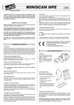
Loosen the handwheel (20) and slightly lift the top cover (21), then forcing it
sideways in the direction shown by the
arrow free the cover from the body of
the projector.
After maintenance, fit the top cover
(21) back on, repeating the previous
sequence in reverse order.
20
ENGLISH
The entire re-calibration cycle lasts approximately 35 seconds and can be stopped at
any time by simply setting a channel at a level above 0.
5
PROJECTOR POSITIONING
Before proceeding, set the channels as shown in the following table.
• Re-lamping
1
2
3
4
5
6
7
CHANNEL
COLOUR DISC
GOBO ROTATION
GOBO SELECTION
DIMMER / STOP / STROBE
PAN
TILT
EFFECTS DISC
CURSOR POSITION
0 % (white spot)
100 % (white spot)
50 % (central position)
50 % (central position)
0 % (white spot)
22
After opening the projector, loosen the
two side ring nuts (22) of the lamp to
replace and remove it from the mountings (23).
Take the new lamp out of its package,
loosen the two side ring nuts (22) and
insert it in the mountings (23). Finally,
screw on the ring nuts.
23
24
22
6
• Light beam centring
After carrying out the operations
described, loosen the knobs (7), proceed by moving the projector on the
bracket (6) to position the beam of
light on the central point of the scene,
then lock the knobs (7).
IMPORTANT: To distribute the beam of light uniformly, the lamp needs to be positioned with the protrusion (24), visible on the bulb, outside the optical axis of the projector. For this purpose it is recommended to turn the protrusion towards towards the
top cover of the projector
7
25
• Replacing fuses
To replace the fuses, press the tab
(25) and take out the fuse-holder box
(26). Replace blown fuses with new
ones of the type specified on the label
(27) on the fuse-holder box (26). Put it
back in so the tab (25) clicks home.
• Adjusting the lens
Move the lens (16) axially to obtain
perfect focusing of the projected
image, then lock the handwheel (17).
16
FUSE
5 x 20
5A T
250 V
27
26
17
• Removing the lens hood plate
• Adjusting the lens hood
Loosen the two handwheels (18),
move the lens hood (19) in the directions shown by the arrows and lock it
in the desired position by tightening
the two handwheels (18).
Check the positioning of the lens
hood by taking the TILT to 100% (with
microswitch 12 in the OFF position)
and moving the PAN from 0% to
100%.
Before carrying out the routine maintenance operations on the effects unit,
described below, it is necessary to
remove the lens hood plate (28) by
unscrewing the two handwheels (29),
take care not to drop them inside the
projector.
After the necessary maintenance, fit
the lens hood plate (28) back on,
securing it with the two handwheels
(29).
18
28
29
19
7