1
Models:
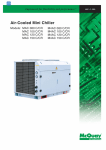
A5ACV 100 CR
A5ACV 135 CR
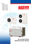
Air-Cooled Chiller
(R410A Inverter Series)
A5ACV - 2005
CONTENTS
PAGE
1. NOMENCLATURE................................................................................................. 1
2. FEATURES............................................................................................................ 2
3. PRODUCT LINE-UP............................................................................................... 3
4. SPECIFICATIONS................................................................................................. 4
5. SOUND DATA.......................................................................................................
8
6. PERFORMANCE TABLE....................................................................................... 9
7. TECHNICAL DATA.................................................................................................. 11
8. OUTLINES AND DIMENSIONS.............................................................................. 13
9. REFRIGERANT CIRCUIT DIAGRAMS................................................................. 14
10. WIRING DIAGRAMS..........................................................................................
15
11. CHILLER PANEL CONTROLLER........................................................................ 16
12. INSTALLATION................................................................................................... 48
13. SPECIAL PRECAUTIONS FOR R410A.............................................................. 52
14. SERVICING AND MAINTENANCE....................................................................
55
15. TROUBLESHOOTING........................................................................................
56
16. EXPLODED VIEW AND PART LIST..................................................................
58
1. NOMENCLATURE
Production spec variation
Type of ref. connection
X: Not Applicable
Electrical
F: 380-415V/3Ph/50Hz
A
5 AC
V 100
C R
-
F
X
AA
Model Type
R: heatpump
Omitted if cooling
Series
C: C series
Capacity
100 : 100,000 Btu/h
Type
Inverter
Model Name
AC: Air cooled mini
chiller
Refrigerant
5 : R410A
Brand
ACSON
1
2. FEATUERS
TRUE DUAL CIRCUITS BPHE
The true dual BPHE puts the secondary circuit (water) in contact with 2 primary circuits (refrigerant). So even
if one primary circuit is shut off, each secondary channel is still in contact with a primary channel.
INVERTER COMPRESSOR
Inverter compressor is programmed to run at the optimum speed, which is regulated by the input frequency
as it can varies according to the heat load requirement.
Inverter advantages are :
• Less start & stop – Frequency regulated compressor resulting in lesser in the sense of start and stop of
compressor, which greatly reduces the energy consumption.
• Fast cooling/heating – Inverter compressor has the ability to produce faster cooling/heating capacity at
the frequency higher than the dominant capacity frequency.
• Smart loading/unloading – with the integration of built in system algorithm; inverter compressor could
control the system’s loading and unloading sophisticatedly.
• Better compressor reliability – Reliability of inverter compressor is always better since there is lesser on/
off of the system especially during low load condition.
ELIMINATION OF WATER TANK
Inverter system provides constant water temperature band, or much lesser water temperature fluctuation.
With this, water tank of the mini chiller system can be eliminated.
BUILT IN FAN SPEED
The built in algorithm now controls fan speed, resulting in cost saving since installation of external FSC (Fan
speed controller) can be exempted.
SAFETY PROCTECTION
•
•
•
•
•
•
•
High & low pressure switches
Anti-freeze protection sensor
Discharge temperature sensor
Over pressure relief valve
Water pressure differential switch
Anti-freeze heater on BPHE
Compressor, water pump overload protector
ANTI CORROSION HEAT EXCHANGER
Gold aluminum fin is offered as standard material of the condenser heat exchanger of this series of chiller.
MODULAR INSTALLATION
A network up to 50chillers in a system is possible. Control on the operation of the chillers will be done through
the microprocessor controller. The external water piping connection can be made either from the left or right
side of the unit.
2
Nomenclature
Wired handset WCCH
Gold Fin
Isolator Switch
Scroll compressor
Capillary tube (normal circuit)
EXV (Inverter circuit)
Pump only
Brass adaptor BSPT 1 1/4
A5ACV
Heat pump model
3. PRODUCT LINE-UP
A5ACV PRODUCT LINE-UP
Classification
100CR
FXAA
X
X
X
X
X
X
X
X
135CR
FXAA
X
X
X
X
X
X
X
X
3
4. SPECIFICATIONS
GENERAL DATA - HEAT PUMP R410A INVERTER
MODEL
Btu/h
NOMINAL COOLING CAPACITY
NOMINAL HEATING CAPACITY
NOMINAL TOTAL INPUT POWER
NOMINAL RUNNING CURRENT
A5ACV100CR
A5ACV135CR
95000
131500
W
27800
38540
Btu/h
100000
141500
W
29300
41470
COOLING
W
12000
15750
HEATING
W
11400
16250
COOLING
A
24.4
30.0
HEATING
A
23.9
POWER SOURCE
31.4
V/Ph/Hz
380-415 / 3 / 50
REFRIGERANT TYPE
R410A
CONTROL
ELECTRONIC EXPANSION VALVE / CAPILLARY TUBE
HEIGHT
mm/in
1260 / 49.6
1260 / 49.6
WIDTH
mm/in
1500 / 59.1
1800 / 70.9
DEPTH
mm/in
900 / 35.4
1150 / 45.3
HEIGHT
mm/in
1452 / 57.2
1452 / 57.2
WIDTH
mm/in
1732 / 68.2
2032 / 80.0
DEPTH
mm/in
1032 / 40.6
1282 / 50.5
UNIT WEIGHT
kg/lb
360 / 794
560 / 1235
SOUND PRESSURE LEVEL
dBA
63
67
COOLING
l/s / m3/hr
1.3 ( 4.8 )
1.8 ( 6.6 )
HEATING
l/s / m3/hr
1.4 ( 5.0 )
2.0 ( 7.1 )
UNIT DIMENSION
PACKING DIMENSION
EVAPORATOR
NOMINAL WATER FLOW
CONDENSER FAN
TYPE/DRIVE
PROPELLER / DIRECT
QUANTITY
2
2
HYDRAULIC KIT
TYPE
PUMP
HORIZONTAL MULTISTAGE END-SUCTION
MAX. WATER OPER. PRESSURE
WATER FLOW RATE
TANK
HEAD
1000 / 145
COOLING
l/s / m3/hr
1.3 ( 4.8 )
HEATING
l/s / m3/hr
1.4 ( 5.0 )
INSTALLATION PIPE CONNECITON
PIPING
kPa / psi
mm/in
2.0 ( 7.1 )
31.75 / 1 1/4
COOLING
m
17.3
HEATING
m
15.7
MATERIAL
CAPACITY/VOLUME
1.8 ( 6.6 )
16.5
14.5
NOT APPLICABLE
L / ft3
NOT APPLICABLE
COMPRESSOR
TYPE
STAGE OF CAPACITY CONTROL (Btu/h)
SCROLL
SCROLL
73000 - 122000
99000 - 149000
4.7 x2 / 10.4 x2
6.0 x2 / 13.2 x2
REFRIGERANT
CHARGING MASS
kg/lb
1) ALL SPECIFICATIONS ARE SUBJECTED TO CHANGE BY THE MANUFACTURER WITHOUT PRIOR NOTICE.
2) ALL UNITS ARE BEING TESTED AND COMPLY TO ISO 5151 & ISO13253.
3) NOMINAL COOLING AND HEATING CAPACITY ARE BASED ON THE CONDITIONS BELOW :
a) COOLING - 12°C / 7°C ENTERING / LEAVING EVAPORATOR WATER TEMPERATURE, 35°C AIR AMBIENT TEMPERATURE.
b) HEATING - 40°C / 45°C ENTERING / LEAVING EVAPORATOR WATER TEMPERATURE, 7°C AIR AMBIENT TEMPERATURE.
4) SOUND PRESSURE LEVEL ARE ACCORDING TO JIS B 8615 JIS C 9612 STANDARD.
4
ELECTRICAL DATA - HEAT PUMP R410A INVERTER
MODEL
A5ACV100CR
INSULATION GRADE
POWER SOURCE
CONDENSER FAN
MOTOR
F
V/Ph/Hz
W
500
RATED RUNNING CURRENT
A
2.2
6.0
MOTOR OUTPUT
W
200 x2
450 x2
INSULATION GRADE
POWER SOURCE
1430
8
6
NA
NA
V/Ph/Hz
380 - 415 / 3 / 50
CAPACITOR
µF
NA
NA
RATED INPUT POWER (COOLING)
W
10500
13520
RATED INPUT POWER (HEATING)
W
9900
14020
RATED RUNNING CURRENT (COOLING)
A
21.9
25.9
RATED RUNNING CURRENT (HEATING)
A
21.3
27.0
LOCKED ROTOR AMP.
A
67 / -
111 / -
INSULATION GRADE
POWER SOURCE
WATER PUMP
F
220 - 240 / 1 / 50
RATED INPUT POWER
POLES
COMPRESSOR
A5ACV135CR
F
V/Ph/Hz
F
380 - 415 / 3 / 50
RATED INPUT POWER (COOLING)
W
1013
882
RATED INPUT POWER (HEATING)
W
1026
907
RATED RUNNING CURRENT (COOLING)
A
2.0
2.0
RATED RUNNING CURRENT (HEATING)
A
2.0
2.0
1) ALL SPECIFICATIONS ARE SUBJECTED TO CHANGE BY THE MANUFACTURER WITHOUT PRIOR NOTICE.
2) ALL UNITS ARE BEING TESTED AND COMPLY TO ISO 5151.
5
COMPONENTS DATA
MODEL
A5ACV100CR
TYPE
CONDENSER
FAN
Q'TY
2
MATERIAL
ALUMINIUM
DRIVE
DIRECT
DIAMETER
CONDENSER
FAN MOTOR
mm/in
609.6 / 24
TYPE
Q'TY
INDEX OF PROTECTION (IP)
2
2
NA
NA
SCROLL + AC INVERTER SCROLL
OIL TYPE
OIL
AMOUNT
POE
POE
3250 / 110
SCROLL
cm3 / fl.oz.
1700 / 57.5
INVERTER S.
cm3 / fl.oz.
2300 / 77.8
TYPE
CONDENSER
COIL
CORRUGATED INNER GROOVED COPPER
DIAMETER
mm/in
9.52 / 3/8
THICKNESS
mm/in
0.372 / 0.015
MATERIAL
THICKNESS
FIN
FACE AREA
ALUMINIUM
mm/in
2
0.12 / 0.005
2
m / ft
1.37 / 14.7
ROW
PUMP
CASING
1.79 / 19.3
2
FIN PER INCH
BPHE
2300 / 77.8
CROSS FINNED TUBES
MATERIAL
TUBE
660.4 / 26
INDUCTION
TYPE
COMPRESSOR
A5ACV135CR
PROPELLER
14
TYPE
BRAZED PLATE HEAT EXCHANGER
MATERIAL
STAINLESS STEEL
TYPE
HORIZONTAL MULTISTAGE END-SUCTION
MATERIAL
CAST IRON & STAINLESS STEEL
MATERIAL
ELECTRO-GALVANIZED MILD STEEL
COLOUR
LIGHT GREY- PE775104
1) ALL SPECIFICATIONS ARE SUBJECTED TO CHANGE BY THE MANUFACTURER WITHOUT PRIOR NOTICE.
6
SAFETY DEVICES
MODEL
A5ACV100CR
HIGH PRESSURE
SWITCH
LOW PRESSURE
SWITCH
SAFETY DEVICE
TYPE
A5ACV135CR
NC
NC
OPEN
Pa / psi
4140 / 600
4140 / 600
CLOSE
Pa / psi
3312 / 480
3312 / 480
TYPE
NC
NC
124 / 18
OPEN
Pa / psi
124 / 18
CLOSE
Pa / psi
193 / 28
PHASE PROTECTION
193 / 28
BUILT IN ON BOARD
DIFFERENTIAL PRESSURE SWITCH
YES
ANTI-FREEZE PROTECTION SENSOR
YES
YES
110 / 230
111 / 230
OVER PRESSURE RELIEF VALVE
YES
YES
ANTI-FREEZE HEATER ON BPHE
YES
YES
PUMP OLP
YES
YES
COMPRESSOR OLP
YES
YES
DISCH. THERMOSTAT SETTING
°C / °F
1) ALL SPECIFICATIONS ARE SUBJECTED TO CHANGE BY THE MANUFACTURER WITHOUT PRIOR NOTICE.
7
YES
5. SOUND DATA
SOUND PRESSURE LEVEL
Model
A5ACV100CR
A5ACV135CR
125Hz
60.7
66.3
1/1 Octave Sound Pressure Level (dB, ref 20µPa)
250Hz
500Hz
1kHz
2kHz
4kHz
58.3
57.4
57.6
56.3
53.2
58.0
58.4
62.0
60.5
58.1
8kHz
53.3
52.0
Overall
(dBA)
62.9
66.7
8kHz
67.8
66.3
Overall
(dBA)
77.6
80.5
Tested according to JIS B 8615 & JIS C 9612
Microphone position : 1m from each side
SOUND POWER LEVEL
Model
A5ACV100CR
A5ACV135CR
125Hz
75.5
79.7
1/1 Octave Sound Power Level (dB, ref 1pW)
250Hz
500Hz
1kHz
2kHz
4kHz
74.7
72.4
72.4
71.0
67.4
72.5
74.0
75.7
74.5
71.3
Tested according to ISO 3741
Model
Measuring location (for Sound Pressure Level)
A5ACV100CR
A5ACV135CR
1m
1m
1m
1m
1m
1m
Standard : JIS B 8615, JIS C 9612
Microphone position : 1m from each side
8
6. PERFORMANCE TABLES
A5ACV135CR
MODEL
A5ACV100CR
A5ACV135CR
MODEL
A5ACV100CR
A5ACV135CR
19
20
25
COOL POWER RUNNING COOL POWER RUNNING
CAP. INPUT CURRENT CAP. INPUT CURRENT
COOL
CAP.
28
POWER RUNNING COOL POWER RUNNING
INPUT CURRENT CAP.
INPUT CURRENT
WATER AVAIL.
FLOW
HEAD
RATE PRESS.
3
PUMP
INPUT
POWER
PUMP
INPUT
AMP
kW
kW
A
kW
kW
A
kW
kW
A
kW
kW
A
m /hr
kPa
W
A
30.76
8.99
18.28
30.29
9.15
18.60
27.91
9.93
20.19
26.48
10.40
21.15
3.98
217.54
951
1.83
5
31.84
9.05
18.39
31.48
9.20
18.71
31.48
10.04
20.42
27.73
10.57
21.49
4.25
203.33
975
1.87
6
32.68
9.09
18.48
32.33
9.26
18.83
32.33
10.16
20.66
28.60
10.72
21.80
4.40
194.90
987
1.90
7
34.00
9.15
18.61
33.88
9.32
18.95
31.59
10.27
20.87
30.22
10.91
22.17
4.79
172.70
1013
1.95
8
34.36
9.18
18.67
34.01
9.38
19.07
34.01
10.40
21.14
30.33
11.03
22.43
4.83
170.46
1015
1.95
9
35.20
9.23
18.76
34.85
9.44
19.18
34.85
10.52
21.38
31.20
11.19
22.74
4.86
168.20
1017
1.95
10 35.80
9.27
18.84
35.34
9.50
19.30
33.06
10.64
21.63
31.69
11.33
23.03
4.90
165.93
1019
1.96
4
42.21
11.84
22.49
41.56
12.05
22.88
38.30
13.08
24.84
36.34
13.70
26.01
5.46
204.78
817
1.81
5
43.69
11.91
22.62
43.20
12.12
23.02
43.20
13.22
25.11
38.05
13.92
26.43
5.83
193.19
838
1.86
6
44.84
11.97
22.73
44.36
12.20
23.16
44.36
13.38
25.41
39.24
14.12
26.82
6.04
186.19
850
1.89
7
46.66
12.05
22.89
46.49
12.27
23.31
43.35
13.52
25.68
41.47
14.36
27.27
6.57
167.40
879
1.95
8
47.15
12.09
22.96
46.67
12.35
23.45
46.67
13.69
26.00
41.62
14.53
27.59
6.62
165.47
881
1.96
9
48.30
12.15
23.08
47.82
12.42
23.60
47.82
13.85
26.30
42.81
14.73
27.97
6.67
163.53
884
1.96
10 49.12
12.20
23.17
48.49
12.50
23.74
45.36
14.01
26.61
43.48
14.91
28.32
6.72
161.57
887
1.97
PUMP
INPUT
POWER
PUMP
INPUT
AMP
LEAVING WATER TEMP (°C)
A5ACV100CR
AMBIENT TEMPERATURE ON CONDENSOR (°C)
4
AMBIENT TEMPERATURE ON CONDENSOR (°C)
30
32
35
COOL POWER RUNNING COOL POWER RUNNING
CAP. INPUT CURRENT CAP. INPUT CURRENT
COOL
CAP.
40
POWER RUNNING COOL POWER RUNNING
INPUT CURRENT CAP.
INPUT CURRENT
WATER AVAIL.
FLOW
HEAD
RATE PRESS.
3
kW
kW
A
kW
kW
A
kW
kW
A
kW
kW
A
m /hr
kPa
W
A
4
25.53
10.72
21.78
24.58
11.03
22.42
23.16
11.50
23.38
20.78
12.28
24.97
3.98
217.54
951
1.83
5
26.79
10.92
22.20
25.85
11.27
22.91
24.72
11.73
23.85
22.10
12.67
25.77
4.25
203.33
975
1.87
6
27.66
11.10
22.56
26.73
11.47
23.33
25.61
11.98
24.36
23.00
12.97
26.37
4.40
194.90
987
1.90
7
29.31
11.33
23.04
28.39
11.76
23.90
27.84
12.00
24.40
24.74
13.46
27.36
4.79
172.70
1013
1.95
8
29.41
11.46
23.29
28.49
11.88
24.15
28.06
12.49
25.39
24.81
13.57
27.59
4.83
170.46
1015
1.95
9
30.29
11.63
23.65
29.37
12.08
24.56
28.28
12.74
25.90
25.72
13.87
28.19
4.86
168.20
1017
1.95
10 30.78
11.78
23.96
38.65
12.24
24.89
28.49
12.93
26.28
26.21
14.07
28.61
4.90
165.93
1019
1.96
4
35.03
14.11
26.79
33.73
14.52
27.58
31.77
15.14
28.75
28.51
16.17
30.71
5.46
204.78
817
1.81
5
36.76
14.38
27.31
35.47
14.84
28.19
33.91
15.45
29.34
30.32
16.69
31.69
5.83
193.19
838
1.86
6
37.96
14.61
27.75
36.68
15.11
28.69
35.14
15.78
29.97
31.56
17.08
32.44
6.04
186.19
850
1.89
7
40.21
14.92
28.34
38.96
15.48
29.40
38.20
15.80
30.01
33.94
17.72
33.66
6.57
167.40
879
1.95
8
40.36
15.08
28.64
39.10
15.64
29.70
38.50
16.44
31.23
34.05
17.87
33.93
6.62
165.47
881
1.96
9
41.56
15.32
29.09
40.30
15.91
30.21
38.80
16.77
31.85
35.29
18.26
34.68
6.67
163.53
884
1.96
10 42.23
15.52
29.47
53.03
16.12
30.61
39.10
17.02
32.33
35.96
18.53
35.19
6.72
161.57
887
1.97
PUMP
INPUT
POWER
PUMP
INPUT
AMP
LEAVING WATER TEMP (°C)
MODEL
LEAVING WATER TEMP (°C)
MODEL : A5ACV100 / 135CR - COOLING
AMBIENT TEMPERATURE ON CONDENSOR (°C)
42
46
COOL POWER RUNNING COOL POWER RUNNING
CAP. INPUT CURRENT CAP. INPUT CURRENT
WATER AVAIL.
FLOW
HEAD
RATE PRESS.
3
kW
kW
A
kW
kW
A
m /hr
kPa
W
A
4
19.83
12.59
25.60
17.93
13.22
26.88
3.98
217.54
951
1.83
5
21.16
13.02
26.48
19.12
14.21
28.88
4.25
203.33
975
1.87
6
22.07
13.35
27.13
20.04
14.48
29.43
4.40
194.90
987
1.90
7
23.82
13.88
28.23
21.51
14.97
30.43
4.79
172.70
1013
1.95
8
23.89
13.99
28.45
21.89
15.02
30.53
4.83
170.46
1015
1.95
9
24.81
14.32
29.10
22.82
15.29
31.08
4.86
168.20
1017
1.95
10 25.30
14.53
29.54
23.47
15.45
31.40
4.90
165.93
1019
1.96
4
27.21
16.58
31.49
24.60
17.41
33.06
5.46
204.78
817
1.81
5
29.03
17.15
32.57
26.24
18.70
35.52
5.83
193.19
838
1.86
6
30.28
17.57
33.38
27.50
19.06
36.20
6.04
186.19
850
1.89
7
32.69
18.28
34.72
29.52
19.71
37.43
6.57
167.40
879
1.95
8
32.79
18.42
34.99
30.04
19.77
37.55
6.62
165.47
881
1.96
9
34.04
18.85
35.80
31.31
20.13
38.23
6.67
163.53
884
1.96
10 34.71
19.13
36.34
32.21
20.34
38.63
6.72
161.57
887
1.97
9
A5ACV135CR
MODEL
A5ACV100CR
A5ACV135CR
MODEL
A5ACV100CR
A5ACV135CR
-7
-5
0
HEAT POWER RUNNING HEAT POWER RUNNING
CAP. INPUT CURRENT CAP. INPUT CURRENT
HEAT
CAP.
POWER RUNNING
INPUT CURRENT
WATER AVAIL.
FLOW
HEAD
RATE PRESS.
3
PUMP
INPUT
POWER
PUMP
INPUT
AMP
A
kW
kW
A
kW
kW
A
m /hr
kPa
W
A
35 28.34
9.48
19.82
29.27
9.52
19.92
31.59
9.64
20.16
6.31
70.13
1049
2.03
40 24.46
10.13
21.19
25.58
10.19
21.33
28.38
10.36
21.67
5.90
100.29
1050
2.03
45 20.58
10.78
22.56
21.90
10.87
22.74
25.17
11.08
23.18
5.04
157.28
1026
1.99
50 16.71
11.44
23.92
18.21
11.54
24.14
21.96
11.80
24.69
4.64
181.53
1003
1.94
55 12.83
12.09
25.29
14.52
12.22
25.55
18.75
12.53
26.21
4.24
203.68
974
1.89
35 38.39
13.55
26.07
39.65
13.61
26.20
42.79
13.78
26.51
7.87
113.65
943
2.03
40 33.13
14.48
27.87
34.65
14.58
28.05
38.45
14.81
28.50
7.33
137.31
917
1.98
45 27.88
15.42
29.67
29.66
15.54
29.91
34.10
15.84
30.49
6.83
157.55
892
1.92
50 22.63
16.35
31.47
24.66
16.50
31.76
29.75
16.88
32.48
6.28
177.85
863
1.86
55 17.38
17.29
33.27
19.67
17.47
33.61
25.40
17.91
34.47
5.75
195.90
834
1.60
PUMP
INPUT
POWER
PUMP
INPUT
AMP
LEAVING WATER TEMP (°C)
A5ACV100CR
AMBIENT TEMPERATURE ON CONDENSOR (°C)
kW
kW
AMBIENT TEMPERATURE ON CONDENSOR (°C)
7
4
10
HEAT POWER RUNNING HEAT POWER RUNNING
CAP. INPUT CURRENT CAP. INPUT CURRENT
HEAT
CAP.
POWER RUNNING
INPUT CURRENT
WATER AVAIL.
FLOW
HEAD
RATE PRESS.
3
kW
A
kW
kW
A
kW
kW
A
m /hr
kPa
W
A
35 31.17
9.73
20.35
36.69
9.80
20.50
36.69
9.80
20.50
6.31
70.13
1049
2.03
40 29.00
10.49
21.94
34.29
10.64
22.25
34.29
10.64
22.25
5.90
100.29
1050
2.03
45 27.80
11.25
23.54
29.31
11.40
23.85
31.47
11.47
24.00
5.04
157.28
1026
1.99
50 24.64
12.01
25.13
26.97
12.18
25.48
29.48
12.31
25.76
4.64
181.53
1003
1.94
55 22.14
12.78
26.73
24.68
12.96
27.12
31.45
13.15
27.51
4.24
203.68
974
1.89
35 42.23
13.91
26.77
45.74
14.07
27.07
49.69
14.01
26.96
7.87
113.65
943
2.03
40 39.28
15.00
28.86
42.60
15.18
29.22
46.44
15.21
29.27
7.33
137.31
917
1.98
45 37.65
16.09
30.96
39.70
16.30
31.37
42.63
16.41
31.57
6.83
157.55
892
1.92
50 33.38
17.18
33.06
36.53
17.42
33.52
39.93
17.60
33.88
6.28
177.85
863
1.86
55 29.99
18.27
35.16
33.43
18.54
35.67
42.60
18.80
36.19
5.75
195.90
834
1.60
PUMP
INPUT
POWER
PUMP
INPUT
AMP
LEAVING WATER TEMP (°C)
MODEL
LEAVING WATER TEMP (°C)
MODEL : A5ACV100 / 135CR - HEATING
kW
AMBIENT TEMPERATURE ON CONDENSOR (°C)
15
21
WATER AVAIL.
HEAT POWER RUNNING HEAT POWER RUNNING FLOW
HEAD
CAP. INPUT CURRENT CAP. INPUT CURRENT RATE PRESS.
3
kW
A
kW
kW
A
m /hr
kPa
W
A
35 42.37
10.00
20.92
47.99
10.09
21.11
6.31
70.13
1049
2.03
40 39.62
10.87
22.73
44.91
11.01
23.04
5.90
100.29
1050
2.03
45 36.71
11.73
24.54
41.84
11.93
24.96
5.04
157.28
1026
1.99
50 34.14
12.60
26.35
38.76
12.85
26.89
4.64
181.53
1003
1.94
55 35.68
13.46
28.16
36.53
13.77
28.81
4.24
203.68
974
1.89
35 57.38
14.30
27.52
65.00
14.43
27.77
7.87
113.65
943
2.03
40 53.67
15.54
29.90
60.84
15.75
30.31
7.33
137.31
917
1.98
45 49.72
16.78
32.28
56.67
17.06
32.84
6.83
157.55
892
1.92
50 46.24
18.01
34.66
52.50
18.38
35.37
6.28
177.85
863
1.86
55 48.33
19.25
37.04
49.48
19.69
37.90
5.75
195.90
834
1.60
kW
10
7. TECHNICAL DATA
WATER PRESSURE DROP VS FLOW RATE
MODEL : A5ACV100CR - COOLING
Flow rate
m3/hr
3.98
4.25
4.40
4.79
4.83
4.86
4.90
Available Head Pressure
kPa
217.54
203.33
194.90
172.70
170.46
168.20
165.93
System Pressure Drop
kPa
19.60
25.24
29.39
38.73
39.54
39.60
39.78
MODEL : A5ACV100CR - HEATING
Flow rate
m3/hr
6.31
5.90
5.04
4.64
4.24
Available Head Pressure
kPa
70.13
100.29
157.28
181.53
203.68
System Pressure Drop
kPa
86.93
71.47
45.37
41.41
28.08
MODEL : A5ACV135CR - COOLING
Flow rate
m3/hr
5.51
5.89
6.10
6.63
6.68
6.73
6.78
Available Head Pressure
kPa
203.30
191.48
184.35
165.20
163.24
161.26
159.26
System Pressure Drop
kPa
51.25
57.61
60.38
71.16
73.16
73.29
73.47
MODEL : A5ACV135CR - HEATING
Flow rate
m3/hr
8.22
7.65
7.13
6.56
6.01
Available Head Pressure
kPa
97.28
123.21
145.40
167.66
187.46
System Pressure Drop
kPa
104.54
91.34
78.24
66.89
59.81
11
CORRECTION FACTORS WITH GLYCOL USE
CAPACITY FACTOR
GLYCOL
LWT/ deg C
10
20
30
40
-5
0.89
0.87
0.77
-3.9
0.9
0.876
0.781
-1.1
0.925
0.925
0.892
0.796
1.7
0.945
0.938
0.906
0.809
4.4
0.956
0.949
0.918
0.82
7.2
0.965
0.958
0.927
0.829
10
0.962
0.957
0.926
0.828
GLYCOL %
WATER
FLOW
PRESSURE
DROP
10
1.015
1.06
20
1.04
1.12
30
1.08
1.18
40
1.135
1.24
12
8. OUTLINES AND DIMENSIONS
MODEL : A5ACV100 / 135CR
Model
F
G
Base Leg Hole
A
B
C
D
E
A5ACV100CR
1500
900
1245
1190
297.5
307.5
1446
A5ACV135CR
1800
1150
1245
1190
347.5
416
1766
H
I
J
K
L
M
A5ACV100CR
100
265
385
60
200
170
A5ACV135CR
10
265
385
60
200
170
Model
13
9. REFRIGERANT CIRCUIT DIAGRAMS
MODEL : A5ACV 100CR
F IN T UB E
HE AT E XC HANG E R
(S Y S T E M 1)
A5ACV 100CR
Refrigerant Circuit Diagram
HE AT ING
C AP
T UB E
4-WAY VALV E
F ILT E R
DR IE R
C HE C K
VALV E
F IN T UB E
HE AT E XC HANG E R
(S Y S T E M 2)
4-WAY VALV E
F ILT E R
DR IE R
E XV
VAR IAB LE S P E E D
C OMP R E S S OR
C OOLING
C AP
T UB E
S UC T ION
AC C UMULATOR
LIQUID
R E C E IV E R
C HE C K
VALV E
S UC T ION
AC C UMULATOR
C OMP R E S S OR
LIQUID
R E C E IV E R
WAT E R
IN
WAT E R
OUT
MODEL : A5ACV 135CR
F IN T UB E
HE AT E XC HANG E R
(S Y S T E M 1)
A5ACV 135CR
Refrigerant Circuit Diagram
HE AT ING
C AP
T UB E
4-WAY VALV E
F ILT E R
DR IE R
C HE C K
VALV E
F IN T UB E
HE AT E XC HANG E R
(S Y S T E M 2)
4-WAY VALV E
F ILT E R
DR IE R
E XV
VAR IAB LE S P E E D
C OMP R E S S OR
C OOLING
C AP
T UB E
S UC T ION
AC C UMULATOR
LIQUID
R E C E IV E R
LIQUID
R E C E IV E R
WAT E R
OUT
WAT E R
IN
14
C HE C K
VALV E
S UC T ION
AC C UMULATOR
C OMP R E S S OR
10. WIRING DIAGRAMS
MODEL : A5ACV 100/135CR
15
11. CHILLER PANEL CONTROLLER
1. SAFETY CONSIDERATION
Only specially trained and technicians and installers are authorized to install and service this
equipment.
1.1 General Installation Recommendations
• Only supply DC voltage (9-17V, typically 12V, maximum current 200mA) as a power source
to the device.
• Input contact voltage supply should limit to 12VDC or 24VAC.
• Isolated all the low voltage wiring (communication bus, etc) from high voltage power supply
wiring.
2. GENERAL DESCRIPTION
2.1 GENERAL
The chiller panel controller is designed to control the chiller operation. This device allows the user
to have customized control for each connected unit.
2.2 FEATURES
The requirements of user friendly and easy to use have been taken into account in designing this
chiller panel controller. It can do the task as follow:
• Whole system configuration
• Unique parameter settings
• Operation status display
• Tracing fault record (easy in hardware troubleshooting)
The display is shown in an 8-lines graphical LCD display. There are 8 dedicated keys available
in the panel,
• Menu selection
• Navigation on the screen
• Modification of the selected value
During first start-up, the panel will have a default configuration (timer schedule, set point,
miscellaneous settings, etc). User can do the changes on that particular configuration later.
2.3 PANEL POSITION
The chiller panel controller can be installed anywhere, as long as it is easy to accessed by
authorized personnel.
The requirements of installation are:
• Avoid exposure to shocks
• Avoid any source of electromagnetic pollution
• Avoid installation on uneven vertical surface
2.4 OPERATION ENVIRONMENTAL CONDITION
•
Temperature:
-10°C to 47°C operating temperature
-20°C to 85°C storage temperature
•
Relative Humidity:
0 to 95% non-condensing
16
3. HARDWARE DESCRIPTION
Legend
1&2
3
4
5
6
7
8
9
10
Navigation key
Execute instruction key
Cancel instruction key
Switching to heat mode shortcut key
Switching to cool mode shortcut key
Toggle ON/OFF shortcut key
Show alarm key
Graphical LCD display
ON/OFF indicator
Legend
1&2
3
4
5
6
7
8
9
10
Chiller terminal unit connection
Not available
CMOS reset jumper (JH2)
Chiller bus resistor or configuration (JH3)
Not available
Not available
Not available
Not available
Backup battery
3.1 Key Explanation
The 2 navigation keys permit item selection and modifying the selected value.
ENTER key is used to execute the navigation instruction
ESC key is used to cancel the navigation instruction
Shortcut key to switch the operation mode in the summary pages
Shortcut key to trigger ON/OFF in the summary pages
Shortcut key to show fault / alarm in the summary pages
17
4. INSTALLATION
4.1 CHILLER BUS
Supported up to 50 units of Chiller
Chiller 0
Chiller Panel 0
(Master)
Chiller 1
Chiller 2
5 way wire (CN8)
Chiller
Communication bus
Chiller Panel 1
(Slave)
CHILLER NETWORK
Chiller panel needs to be energized with +12Vdc. The 5 way wires that provided is once on the easiest
solution to establish a communication between the panel and chiller main board (CN8-JP13). If the 5-way
wires socket has been occupied in main board, just using 2 insulation wired are needed to establish a communication between panel and chiller main board.
Chiller panel can support maximum up to 50 units of chiller. In the chiller network, duplication of main board
unit address is not allowed. Each chiller main board should have their unique unit address (0-50).
For first time running, user need to assign a unique unit address to each main board in the chiller network.
User should follow the procedure below:
•
•
Only power ON one main board at once time. Make sure not others main boards are energized.
By using the panel connected to the main board.
<ENTER>
Sum m ary Pages
<ENTER>
Main Menu
Setting Menu
<ENTER>
G7 Unit No
1. General
Set Paraam eter
<ENTER>
<ENTER>
key in "0001" as passw ord
•
•
Key in unique unit address and press ENTER to execute.
De-energized the main board and repeat the procedures again all the main boards have been
assigned a unique unit address.
IMPORTANT : Do not assign a same unit address to more than one chiller main board.
RECOMMENDATION : Please select a coherant model (G1 Model) to all the chiller main boards in
the same network.
18
4.2 OTHERS CONFIGURATION
•
•
•
JH2 in chiller panel should let it open (put the jumper header on one pin only) all the time
unless user need to do CMOS reset to that particular panel.
JH3 should let it open (put the jumper header on one pin only) all the time as well.
Remember to put in the coin cell battery on the panel. Without the backup battery, the panel will
always reset the time to 12:00am, 1st Jan 2000.
4.3 INSTALLATION OF THE CHILLER PANEL CONTROLLER
•
•
•
•
•
•
•
Disconnect the unit and ensure no others unit energy source that supplies the panel.
Open the rear panel of the Chiller Panel (insert a ‘flat-head’ screwdriver in the top joint of main
casing with rear panel to open the real panel).
Pass the necessary wires of the panel across the large opening in the rear panel. Place the rear
panel flat support against the wall and make marks on the wall through the four installation holes
(inner and outer).
Drill four appropriate holes in the marked places.
Attach the rear panel to the wall and put on the screws on it. Ensure that all cables are passed
through the hole of the rear panel.
Connect the wires to the corresponding terminal according to the wiring bus network. The
power supply and communication wires must be correctly connected to ensure that the
panel works.
Close the chiller panel (ensure the bottom joint is aligned for the casing, then complete others joint
part. Ensure that the contacts at the back of the panel are aligned with each others).
JP13
JP13
BUS WIRING DIAGRAM
19
5. SOFTWARE DESCRIPTION
5.1 INTRODUCTION
The Chiller Panel Controller can be used to control / display the status of Chiller.
Status viewing:
• ON/OFF status
• Mode (Cooling / Heating/ Boiling)
• Mode set temperature
• Compressor status (ON/OFF/ DEFROST)
• Water in, Water Out, Outdoor air and Panel temperature
• Chiller model (Chiller, Heat Pump, Chiller/ Boiler, Chiller+Boiler, Heat Pump/Boiler, Heat Pump+
Boiler)
• Advance parameter settings
• Defrost sensor temperatures
• Compressor discharge sensor temperatures
• Compressor run times
• Incoming alarm/ fault/ error
Status settings:
• ON/OFF switching
• Mode setting (Cooling / Heating/ Boiling)
• Mode set temperature
• Manual entering defrost
• Advance parameter settings
• Password changing
• Panel option setting (Backlight, Alarm Buzzer, Screen saver, Contrast, Brightness, temperature
unit)
• Time and date settings
• Clearing compressor run time
20
5.2 MENU STRUCTURES
Status
Mode
Operation Menu
Cool Set
Heat Set
General
Manual Defrost
Regulator
Compressor
Set Parameter [#]
Defrost
Main Menu
Change
Password [#]
Antifreeze
Panel Option
Inverter
Set Panel ID
Alarm and
Contact
Settings Menu
Summary Pages
Clock Setting
Unit Selection
Menu
Date Setting
Timer Menu
Time Schedule
Timer
Show Alarms
Alarm Menu
Erase All Alarms
Defrost Sensor
Discharge Sensor
Display Menu
Comp Run Time
[#]
Inverter Chiller
[#] – Password required
21
5.3 CHILLER MENU STRUCTURE
5.3.1 SUMMARY PAGES
There are 4 pages in [Summary Pages]. Press UP or DOWN for page scrolling. Press ENTER to go to
[Main Menu]. Time and date are shown on top of each page. Beside that, the bottom of each page shows
current control unit of the Chiller.
For example:
[00] - Chiller Panel controls Chiller ID 0 currently
[03] - Chiller Panel controls Chiller ID 3 currently
[All] - Chiller Panel controls all Chiller currently
1st page: Display ON/OFF status, Mode settings and Temperature settings.
01/01/2000
12:00am
Status
: ON
Mode
: Cooling
Cool Temp
: 12.0°C
[00]
2nd page: Display Compressor status.
01/01/2000
Compressor
12:00am
: ON
[00]
3rd page: Display Water In, Water Out, Outdoor air and Panel temperature
01/01/2000
Water In
Water Out
Outdoor Air
Panel
12:00am
:19.8°C
: 25.6°C
: 32.2°C
: 20.5°C
[00]
4th page: Display Chiller model, Compressor No. and Chiller ID.
01/01/2000
12:00am
Model
: Chiller
No. Comp
: 1 Comp
Unit No
:0
22
5.3.2 MAIN MENU
Press ENTER in [Summary Pages] to go into this menu
MAIN MENU
Operating Menu
Setting Menu
Timer Menu
Alarm Menu
Display Menu
There are 5 sub menus in [Main Menu]. Press UP or DOWN to select sub menus, ENTER to enter into
the sub menu or press ESC to exit to [Summary Pages]
5.3.2.1 OPERATION MENU
Select [Operation Menu] in [Main Menu] and press ENTER to go into this menu.
OPERATION MENU
Status
: ON
Mode
: Cooling
Cool Temperature : 12.0°C
Heat Temperature : 40.0°C
Some normal settings can be found here. Press UP or DOWN to select each settings, ENTER to start the
setting or press ESC here to exit to [Main Menu]
Settings : -ON/OFF unit
- Mode changing (Cooling/ Heating/ Boiling)
- Cooling temperature setting
- Manual Defrost Selection
5.3.2.1.1 MANUAL DEFROST
Select [Manual Defrost] in [Operation Menu] and press ENTER to go into this menu.
Defrost Compressor
Comp 1
This menu lets user select one compressor to enter into defrost cycle manually, as long as the
environment fulfill the defrost requirement.
23
5.3.2.2 SETTINGS MENU
Select [Settings Menu] in [Main Menu] and press ENTER to go into this menu.
SETTINGS MENU
Set Parameter
Change Passw ord
Panel Option
Set Panel ID
Some advance settings can be found here. Press UP or DOWN to select settings, ENTER to start the
setting or press ESC here to exit to [Main Menu].
Settings
- Set Parameter
- Password Changing
- Panel Option
- Set Panel ID
5.3.2.2.1 SET PARAMETER
Select [Set Parameter] in [Settings Menu] and press ENTER to go into this menu.
1.
2.
3.
4.
5.
6.
7.
General
Regulator
Compressor
Defrost
Antifreeze
Inverter
Alarm and Contact
There are 7 groups of advance parameters for user to set in this menu, Press UP or DOWN to
select the group, ENTER to go into the group or ESC to exit to [Setting Menu].
Settings:
- General
- Regulator
- Compressor
- Defrost
- Antifreeze
- Inverter
- Alarm and Contact
5.3.2.2.2 PASSWORD CHANGING
Select [Password Changing] in [Setting Menu] and Press ENTER to go into this menu.
Please enter the
Old passw ord ………..
0
- - --
User can change the old password in this menu.
Press ESC to exit to [Settings Menu].
24
5.3.2.2.3 PANEL OPTION
Select [Panel Option] in [Setting Menu] and Press ENTER to go into this menu.
Backlight
Buzzer
Screen Saver
Timeout
Contrast
Brightness
Temp Unit
: Norm al :
: On
: Disable
: 5m
: 50%
: Medium
:°C
User can do some miscellaneous for the panel. These settings would not affect whole system performance.
Settings - Toggle Backlight
- Alarm Buzzer
- Enable / Disable Screen Saver
- Screen Saver timeout
- Contrast display
- Backlight brightness
- Temperature unit
Press ESC to exit to [Settings Menu]
5.3.2.2.4 SET PANEL ID
Select [Set Panel ID] in [Settings Menu] and press ENTER to go into this menu.
Please enter the
Panel ID……
=> Unit 0
User can assign the ID no, to the panel.
Example: If ID no. 0 has been assigned, the panel acts like Master Panel Unit. It can choose to control
each Chiller in the network.
If other ID no. (1-50) has been assigned, the panel acts like Slave Panel Unit. It is dedicated to
one particular Chiller. It can only control the Chiller with same ID in the network.
Press [ESC] to exit to [Settings Menu]
25
5.3.2.3 TIMER MENU
Select [Timer Menu] in [Main Menu] and press ENTER to go into this menu.
TIMER MENU
Clock Setting
Date Setting
Time Schedule
Timer : Disable
:
All the timer/ schedule settings are included in this menu. Press UP or DOWN to select each settings.
ENTER to start the setting or press ESC here to exit to [Main Menu].
Settings:
- Set Clock
- Set Date
- Set Schedule ( 7 days Programmable Timer)
- Enable/ Disable Timer Schedule
5.3.2.3.1 SET CLOCK
Select [Clock Setting] in [Timer Menu] and press ENTER to go into this menu.
Set Time :
hh: mm
00: 00
User can set the time in this menu. The time setting is in 24-hour format.
Pres [ESC] to exit to [Timer Menu].
26
5.3.2.3.2 SET DATE
Select [Date Setting] in [Timer Menu] and press ENTER to go into this menu.
Set Date :
yyyy mm dd
2000 / 01 / 01
User can set the date in this menu. The date is set according to sequence below:
(year) / (month) / (day)
Press [ESC] to exit to [Timer Menu].
5.3.2.3.3 SET SCHEDULE
Select [Schedule Timer] in [Timer Menu] and press ENTER to go into this menu.
Sun
Mon
Tue
Wed
Timer 1
ON OFF
Timer 2
ON OFF
0800 1600
0800 1600
0800 1600
0800 1600
____
____
____
____
____
____
____
____
This is the 7 days programmable timer schedule menu. There are 2 ON/OFF events in one day. User can
choose to set each day of week (Sunday - Saturday) ON/OFF timer. Before this schedule carry their
effect to the Chiller, user need to set the [Timer] in [Timer Menu] to enable.
Press [ESC] to exit to [Timer Menu].
5.3.2.4 ALARM MENU
Select [Alarm Menu] in [Main Menu] and press ENTER to go into this menu.
ALARM MENU
Show Alarms
Erase All Alarm
This place keeps records for all previous occurred fault/ alarms. User can view the alarm history and clear
that record (alarm history) as well. The panel can keep up to 20 fault/ alarm records.
Press ESC to exit to [Main Menu]
27
5.3.2.4.1 SHOW ALARMS
Select [Show Alarms] in [Alarm Menu] and press ENTER to go into this menu.
[Ch 0]
Alarm 1
Comp 1 overload
01/ 01/ 00
12:00am
User can view all the fault/ alarm records in this menu.
The record shows
- Alarm type
- Alarm occurred date
- Alarm occurred time
- Alarm occurred unit (Chiller ID)
Beside that, user can erase the alarm record in this menu.
Press [ESC] to exit to [Alarm Menu].
5.3.2.4.2 ERASE ALL ALARMS
Select [Erase All Alarms] in [Alarm Menu] and press ENTER to go into this menu.
Are you sure ?
Press Enter to erase,
or ESC to exit.
User can erase all the alarm / fault records at once in this menu.
Press [ESC] to exit to [Alarm Menu].
5.3.2.5 DISPLAY MENU
Select [Display Menu] in [Main Menu] and press ENTER to go into this menu.
DISPLAY MENU
Defrost Sensor
Discharge Sensor
Comp Run Time
Inverter Chiller
This menu display Defrost Sensor temperature, Compressor Discharge sensor temperature,
Compressor Run Time and Inverter Chiller. Beside that, user can clear each Compressor
Run Time for Chiller.
Press [ESC] to exit to [Main Menu]
28
5.3.2.5.1 DEFROST SENSOR
Select [Defrost Sensor] in [Display Menu] and press ENTER to go into this menu.
Defrost Sensor
Comp 1 : 12.8°C
User can view the defrost sensor temperature for each compressor in the Chiller.
Press [ESC] to exit to [Display Menu]
5.3.2.5.2 DISCHARGE SENSOR
Select [Discharge Sensor] in [Display Menu] and press ENTER to go into this menu.
Discharge Sensor
Comp 1 : 36.5°C
User can view the discharge sensor temperature for each compressor in the Chiller.
Press [ESC] to exit to [Display Menu].
5.3.2.5.3 COMP RUN TIME
Select [Comp Run Time] in [Display Menu] and press ENTER to go into this menu.
Comp Run Time
Comp 1 : 13579h
User can view the compressor run time for each compressor in the Chiller. Beside that, user can
clear each compressor run time in this menu. User needs to key in the correct password before
clearing the compressor run time.
Press [ESC] to exit to [Display Menu].
5.3.2.5.4 INVERTER CHILLER
Select [Inverter Chiller] in [Display Menu] and press ENTER to go into this menu.
Inverter Chiller
Comp. Freq
Exv.
Comp. Amp
DC Bus
Suction
BPHE in
BPHE out
Condenser
: 100Hz
: 180
: 11.0A
: 516V
: 13.3°C
: 6.0°C
: 12.9°C
: 43.0°C
This menu display compressor frequency, EXV opening, DC voltage, Current, Suction Sensor,
BPHE in sensor, BPHE out sensor and condenser in sensor.
Press [ESC] to exit to [Display Menu].
29
6. OPERATION USER MANUAL
6.1 STARTING
Chiller panel can be set as Master or Slave panel unit. When the Panel ID is set to ‘0’, it acts like a Master
panel, whereas it is Slave panel if Panel ID is set to others number (1-50).
Chiller panel can control the Chiller if both ID no. (Panel ID and Chiller ID) are same.
For example: Panel ID 1 can only control Chiller ID 1
Master Panel can choose to control each Chiller or control all Chiller at once in the network.
For example : Panel ID 0 (master) can control Chiller ID 0 / ID 1/ ID 32 .... or all Chillers at once.
Panel ID can be set in Set Panel ID in Settings Menu.
Please enter the
Panel ID ……
=> Unit 0
30
6.2 CHILLER OPERATION CONTROL
6.2.1 STARTING
During power on for the Chiller Panel, it needs to take several times to collect information from the Chiller.
At this time, all the status will show “--”. Please ensure the particular Chiller exists in the network. When
the process is completed, user can start to control the Chiller using the panel.
01/01/2000
12:00am
01/01/2000
12:00am
Status
: --
Status
: ON
Mode
: --
Mode
: Cooling
Cool Temp
: --
Cool Temp
: 12°C
[00]
In gathering information process
[00]
Gathering information completed
6.2.2 CHANGING DISPLAY UNIT
Chiller Panel (Master) can choose to choose to control / display each Chiller status. This can be done in
[Summary Pages] only.
01/01/2000
12:00am
Status
: ON
Mode
: Cooling
Cool Temp
: 12°C
In [Summary Pages], press and hold ENTER buttom
(1 second) to go into [Unit Selection] menu.
[00]
Unit Selection
:
Select All
Select One
:0
Unit Selection
:
Select All
Select One
Select “Select All” and press ENTER if user want to
control all Chilelr in the network, or select “Select One”
to control a particular Chiller. Press ESC to exit to
[Summary Pages].
Select a Chiller ID via UP or DOWN and press ENTER
to confirm or ESC to cancel.
:0
31
6.2.3 SWITCHING ON/OFF
There are several ways to switch ON/OFF for the Chiller.
i) [Summary Pages]
Press and hold ON/OFF button (hold 1 second). Please note that the ON/OFF button will only function in
[Summary Pages].
ii) [Operation Menu]
<ENTER>
Summary Pages
<ENTER>
Main Menu
Operation Menu
<ESC>
OPERATION MENU
Status
: ON
Mode
: Cooling
Cool Temperature : 12.0°C
Heat Temperature : 40.0°C
<ESC>
In [Operation Menu], select “Status” and press
ENTER.
OPERATION MENU
Status
: ON
Mode
: Cooling
Cool Temperature : 12.0°C
Heat Temperature : 40.0°C
Toggle ON/OFF via UP or DOWN button, and then
press ENTER to confirm the change or ESC to cancel.
iii) [Timer Menu]
<ENTER>
Summary Pages
<ENTER>
Main Menu
Timer Menu
<ESC>
<ESC>
7 days programmable time can turn chiller ON/OFF. User can set the schedule in this
[Timer Menu]. Please refer 6.2.11 (page 40) for schedule settings.
32
6.2.4 SWITCHING MODE
There are several ways to switch the mode for the Chiller. Please take note that some mode cannot be set
due to current Chiller model settings.
Chiller Model
Chiller
Heat Pump
Chiller / Boiler
Heat Pump / Boiler
Chiller + Boiler
Heat Pump + Boiler
Cooling
√
√
√
√
√
√
Mode
Heating
x
√
x
√
x
√
Boiling
x
x
√
√
Auto
Auto
√
- Allow to set
x
- Not Allow to set
Auto
- Turn ON automatically
i) [Summary Pages]
Cooling - Press and hold COOL button.
Heating - Press and hold HEAT button (if it allows to set).
Boiling - Press and hold HEAT button again (if it allows to set).
ii) [Operation Menu]
<ENTER>
Summary Pages
<ENTER>
Main Menu
<ESC>
Operation Menu
<ESC>
OPERATION MENU
Status
Mode
Cool Temperature
Heat Temperature
: ON
: Cooling
: 12.0°C
: 40.0°C
OPERATION MENU
Status
Mode
Cool Temperature
Heat Temperature
: ON
: Cooling
: 12.0°C
: 40.0°C
In [Operation Menu], select “Mode” and press
ENTER to start setting or ESC to exit to [Main Menu]
Toggle ON/OFF via UP or DOWN button, and then
press ENTER to confirm the change or ESC to
cancel.
33
6.2.5 CHANGING MODE SET TEMPERATURE
There are 2 ways to change the mode set temperature for the Chiller.
i) [Operation Menu]
<ENTER>
Summary Pages
<ENTER>
Main Menu
<ESC>
OPERATION MENU
Status
: ON
Mode
: Cooling
Cool Temperature : 12.0° C
Heat Temperature : 40.0° C
OPERATION MENU
Status
: ON
Mode
: Cooling
Cool Temperature : 12.0° C
Heat Temperature : 40.0° C
1. General
2. Regulator
3. Compressor
4. Defrost
5. Antifreeze
6. Inverter
7. Alarm and Contact
Operation Menu
<ESC>
In [Operation Menu], select “Cool Temp” / “Heat
Temp”and press ENTER start setting or ESC to exit
to [Main Menu].
Change value via UP or DOWN button, and then press
ENTER to confirm the change or ESC to cancel.
In [Set Parameter], select “Regulator” and press
ENTER. Press ESC to exit to [Main Menu].
R1 Cool SP
: 12.0°C
R2 Cool Diff
: 3.0°C
R3 Heat SP
: 40.0°C
R4 Heat Diff
: 3.0°C
R5 Min Cool SP : -20°C
R6 Max Cool SP : 40°C
R7 Min Heat SP : -20°C
Select “R3”/ “R5” and press ENTER to start setting
or ESC to exit to [Set Parameter] menu.
R1 Cool SP
: 12.0°C
R2 Cool Diff
: 3.0°C
R3 Heat SP
: 40.0°C
R4 Heat Diff
: 3.0°C
R5 Min Cool SP : -20°C
R6 Max Cool SP : 40°C
R7 Min Heat SP : -20°C
Change value via UP or DOWN button. The
boarderline is limited by R5&R6 (cool), R7&R8(heat).
Press ENTER to confirm or ESC to cancel.
34
6.2.6 MANUAL DEFROST
User can choose which compressor will go into manual defrost cycle by using the Chiller Panel, as long
as the condition is fulfilled with defrost condition. This can be done in [Operation Menu].
<ENTER>
Summary Pages
<ENTER>
Main Menu
<ESC>
Operation Menu
<ESC>
Please take note that “Manual Defrost” option will only available in HEATING mode. It will disappear in
COOLING/ BOILING mode.
OPERATION MENU
OPERATION MENU
Status
: ON
Mode
: Heating
Cool Temperature : 12.0°C
Heat Temperature : 40.0°C
Status
: ON
Mode
: Cooling
Cool Temperature : 12.0°C
Heat Temperature : 40.0°C
“Manual Defrost” disappear when Chiller not in HEATING mode
OPERATION MENU
Status
: ON
Mode
: Heating
Cool Temperature : 12.0°C
Heat Temperature : 40.0°C
Manual Defrost
In [Operation Menu], select [Manual Defrost], press
ENTER to go into it, or ESC to exit to [Main Menu].
Defrost Compressor
Comp 1
Select which compressor to go into defrost cycle via
UP or DOWN button. Press ENTER to confirm or ESC
to exit to [Operation Menu].
35
6.2.7 ADVANCE PARAMETER SETTINGS
The Chiller Panel provide user a lot of advance parameter settings for the Chiller. The parameters are
divided into 7 groups. There all are stored in [Set Parameter] menu and it is password-protected layer
in the panel.
* CAUTION : INPROPER SETTINGS WILL CAUSE PERMANENT DAMAGE TO THE CHILLER !!!
<ENTER>
Summary Pages
<ENTER>
Main Menu
Settings Menu
<ESC>
<ESC>
<ENTER>
Key in Password
Set Parameter
7 groups of Advance Parameter:
1) General
G1 Mode
G2 No. Comp
G3 On/Off in
G4 Cool/Heat in
G5 Ext Alarm in
G6 Water sys
G7 Unit No
: Chiller
: 1 Comp
: Disable
: Disable
: Disable
: Isolated
:0
2) Regulator
R1 Cool SP
: 12.0°C
R2 Cool Diff
: 3.0°C
R3 Heat SP
: 40.0°C
R4 Heat Diff
: 3.0°C
R5 Min Cool SP : -20°C
R6 Max Cool SP : 40°C
R7 Min Heat SP : -20°C
R8 Max Heat SP : 90°C
R9 Ax Heat SP : 5.0°C
R10 Ax Heat Diff : 2.0°C
R11 Au Bo SP : 5.0°C
R12 Au Bo Diff : 2.0°C
R13 Au Bo Start : 30m
36
<ESC>
3) Compressor
C1 Min Run
: 12s
C2 Min Stop
: 240s
C3 2On Interval : 360s
C4 2Cp ON Dly : 15s
C5 P-Cp ON Dly : 60s
C6 Cp-P OFF Dly: 40°C
C7 Cp Cut Off : 120°C
4) Condenser Defrost
D1 Start Temp
D2 End Temp
D3 Max Dura
D4 Interval
D5 Dly Bfr Def
D6 Dly Aft Def
: -3°C
: 14°C
: 10m
: 45m
: 0s
: 0s
5) Cool Mode Antifreeze
A1 Heater SP
A2 Heater Diff
A3 Sensor
A4 Alarm SP
A5 Alarm Diff
: 5°C
: 2.0°C
: Leave
: 3°C
: 2.0°C
6) Inverter
V1 Cp Freq
V2 EXV
V3 Cp Manual
V4 EXV Manual
V5 Def Mode
: 100Hz
: 180
: Disable
: Disable
: Disable
7) Alarm and Contact
P1 FS Confirm
P2 FS Delay
P3 LP Delay
P4 CO Reset
P5 HP Reset
P6 LP Reset
P7 FO Reset
: 5s
: 180s
: 30s
: Manual
: Auto
: Auto
: Manual
P8 RO Reset
P9 FS Reset
P10 Aux Reset
P11 A/F Reset
P12 CO Contact
P13 HP Contact
P14 LP Contact
Please refer to 8. APPENDIX for detail desciption.
37
: Manual
: Manual
: Manual
: Manual
: Normal
: Normal
: Normal
P15 FO Contact
P16 PO Contact
P17 FS Contact
P18 EA Contact
P19 DE Contact
: Normal
: Normal
: Normal
: Normal
: Normal
6.2.8 CHANGING PASSWORD
For security purpose, some places in the panel are password-proctected. User can change the password
at anytime.
<ENTER>
Summary Pages
<ENTER>
Main Menu
Settings Menu
<ESC>
<ESC>
<ENTER>
<ESC>
Change Password
Please enter the
Old password ----------0
----
User needs to enter the old password in order to change
the password.
Change the 1st digit value via UP or DOWN. Press
ENTER to start enter 2nd digit and the rest, or ESC to
exit at anytime.
Password accepted . . .
Password error . . .
Access granted !
Access denied !
If password not correct, this message will be
shown and exit to [settings Menu]
If password correct, this message will be
shown and proceed to new password
settings.
Please enter the
New password ----------0
----
Same as previous, UP DOWN to change value, ENTER
to go to next digit, ESC to exit.
User is not allowed to set the password to 0000.
New password
Has been set …….
New password
‘0 0 0 0’
Is not accepted ………
If new password is accepted, this message
will be shown and then exit to [Settings Menu].
If new password is ‘0000’, this message
will be shown and then exit to [Settings Menu].
The password remains as previous.
38
6.2.9 CLOCK SETTING
User can set the clock for the panel.
<ENTER>
Summary Pages
<ENTER>
Main Menu
Timer Menu
<ESC>
<ESC>
<ENTER>
<ESC>
Set Time
Set Time :
UP or DOWN to change ‘hour’. ENTER to set ‘minute’
or ESC to exit to [Timer Menu].
hh mm
00 : 00
UP or DOWN to change ‘minute’. ENTER to confirm
or ESC to set ‘hour’again.
6.2.10 DATE SETTING
User can set the date for the panel.
<ENTER>
Summary Pages
<ENTER>
Main Menu
<ESC>
Timer Menu
<ESC>
<ENTER>
<ESC>
Set Time
Set Time :
yyyy hh mm
2000 /01 / 01
UP or DOWN to change ‘year’. ENTER to set ‘month’ or
ESC to exit to [Timer Menu].
UP or DOWN to change ‘month’. ENTER to set ‘day’ or
ESC to set ‘year’ again.
UP or DOWN to change ‘day’. ENTER to confirm or
ESC to set ‘month’ again.
39
6.2.11 7 DAYS PRPGRAMMABLE SETTING
The are 2 ON/OFF events in one day for the schedule. This schedule is applicable to all the chillers in
the network.
<ENTER>
Summary Pages
<ENTER>
Main Menu
Timer Menu
<ESC>
<ESC>
<ENTER>
<ESC>
Set Schedule
Sun
Mon
Tue
Wed
Sun
Mon
Tue
Wed
Timer 1
ON OFF
Timer 2
ON OFF
0800 1600
0800 1600
0800 1600
0800 1600
____
____
____
____
Timer 1
ON OFF
Timer 2
ON OFF
UP or DOWN select event. ENTER to start
setting or ESC to back to select day of week.
0800 1600
0800 1600
0800 1600
0800 1600
____
____
____
____
Event setting is same like time setting. User can
disable the event by set it to ‘- - - -’
____
____
____
____
____
____
____
____
UP or DOWN select day of week, ENTER
to select event or ESC to exit to [Timer Menu].
Before the schedule will carry the effect, user need to set ENABLE for “TIMER” in [Timer Menu].
TIMER MENU
Set Time
Set Date
Set Schedule
Timer : Disable
Select “Timer” and press ENTER to start the
settings. UP or DOWN to toggle Enable/ Disable,
ENTER to confirm or ESC to cancel.
40
6.2.12 VIEWING ALARM / ERASE ALARM RECORD
Whenever a new fault/ alarm is occurred, there will be a message pop up to show the fault/ alarm.
Backlight will blinking with beeping sound (if “Alarm Buzzer” is set ON). If the fault/ alarm has not been
dissolved from the Chiller, a sign [A] will be shown in the [Summary Pages].(from pop up menu)
automatically if the fault/ alarms have been dissolved.
While the fault/ alarms have not been dissolved (sign [A]), user can check that fault/ alarm by to into
[Alarm Menu]. If all the fault/ alarm have been dissolved, user can view the fault/alarm historty records
in [Alarm Menu] as well. Screen saver will be deactivated while all the alarms have not been dissolved.
If panel ID is set 0 (Master panel), it can receive and view all the fault / alarms from all chillers in the
network.
[Ch 0]
New Alarm 1
Comp 1 overload
12:00am
01/ 01/ 2000
[Ch 0]
New Alarm 1
Comp 1 overload
01 / 01/ 00
[Ch 0] show alarm occurred unit.
Press any button to stop backlight blinking and beeping.
Press ESC again to exit to normal page.
Press UP or DOWN to scroll the record.
Press ENTER if user want to erase the record, or ESC
to exit to [Alarm Menu].
12:00am
Erase Alarm ?
Please Enter to Erase,
Or ESC to exit
Press ENTER to erase the alarm, or ESC to cancel.
User can erase all the fault/ alarm record at once time through [Erase All Alarm] in [Alarm Menu].
41
6.2.13 VIEWING DEFROST SENSOR TEMPERATURE
The Chiller Panel displays defrost sensor temperature for each compressor in [Defrost Sensor]
in [Display Menu].
Defrost Sensor
Comp 1 : 12.8°C
Press ESC to exit to [Display Menu]
6.2.14 VIEWING COMPRESSOR DISCHARGE TEMPERATURE
The Chiller Panel displays compressor discharge temperature for each compressor in [Discharge Sensor]
in [Display Menu].
Discharge Sensor
Comp 1
: 36.5°C
Press ESC to exit to [Display Menu]
42
6.2.15 VIEWING / CLEAR COMPRESSOR RUN TIME
User can view/ clear the compressor run time for the Chiller in [Comp Run Time] in [Display Menu].
Comp Run Time
Press UP or DOWN to select the compressor. ENTER
to start clear the run time, or ESC to exit to [Display
Menu].
Comp 1 : 13579h
Clear Run Time ?
Press Enter to Clear
Or ESC to exit.
Press ENTER and key in the password to confirm or
ESC to cancel
6.2.16 VIEWING INVERTER CHILLER
<ENTER>
Summary Pages
<ENTER>
Main Menu
Display Menu
<ESC>
<GO>
<ENTER>
<ESC>
Inverter Chiller
Inverter Chiller
Comp. Freq
Exv.
Comp. Amp
DC Bus
: 100Hz
: 180
: 11.0A
: 516V
Suction
BPHE in
BPHE out
Condenser
: 13.3°C
: 6.0°C
: 12.9°C
: 43.0°C
Press ESC to exit to [Display Menu]
6.2.17 MISCELLANEOUS SETTINGS
User can do some miscellaneous settings to the panel.
Backlight
Buzzer
Screen Saver
Timeout
Contrast
Brightness
Temp Unit
: Normal :
: On
: Disable
: 5m
: 50%
: Medium
:°C
Press UP or DOWN to select the item. ENTER to set,
or ESC to exit to [Settings Menu].
Press UP or DOWN to toggle the value. ENTER to confirm,
or ESC to cancel.
43
Parameter
Value
Description
Backlight
Normal
Always
ON
OFF
Enable
Disable
1-30m
0-100%
OFF
Low, Medium, High
°C
°F
Turn ON backlight for 30s via key press
Always ON backlight
Enable beeping sound when fault/ alarm occurred
Disable beeping sound when fault/ alarm occurred
Show screen saver when timeout
No screen save
Timeout for showing screen saver
Adjust the contrast setting for the LCD panel
No backlight
Adjust the backlight intensity
Display temperature in degree Celsius
Display temperature in degree Fahrenheit
Buzzer
*Screen Saver
*Timeout
Contrast
Brightness
Temp Unit
* This product must be branded. Screen saver will be deactivated for brand less panel
6.3 CMOS RESET
•
CMOS reset allows user to reset some settings to default value such as:
Password
Backlight
Buzzer
Screen Saver
Timeout
Contrast
Brightness
Temp Unit
•
-> 0001
-> Normal
-> ON
-> Disable
-> 5m
-> 50%
-> Medium
-> °C
Procedures
1. Power OFF the panel
2. Close the jumper JH2 with the provided jumper header
3. Power ON the panel and the LCD panel should display as follow:
CMOS reset completed !
CMOS is resetting …………
Please remove JUMPER
and restart the panel
4. Remove the jumper header (put the jumper header on 1 pin only), power OFF and then
power ON the panel.
44
7. PROBLEM AND TROUBLESHOOTING
Symptoms
1 Panel gets hot
abnormally
2 The LCD no display
(blank screen)
3 - -' for all status
(quite a long time)
4 ON/ OFF, COOL or
HEAT button not
function
5 Cannot switch to
HEATING mode
6 Cannot switch to
BOILING mode
7 No "Manual Defrost"
item
8 Cannot step inside
[Set Parameter]
Possible Cause
- Wiring fault in 12VDC supply
Troubleshooting
- Change a new panel module and turn ON the unit again
after the verification
- Correct the wiring problem
- Check the wiring and supply 12VDC to panel
- Check the power source
- Change a new panel module
- Ensure the selected unit exits in the network
- Ensure the wiring is correct
- Ensure the wiring is not defective
-Ensure the wiring has been isolated from high power cable
- Select a coherent unit address on the panel (refer to
6.2.2)
- Change a new module
- Ensure it is pressed (hold 1s) in [Summary Pages]
not in other menu.
- Change a new module
- Ensure this mode is available in current "Model" of
Chiller, please refer to 6.2.4
- Ensure this mode is available in current "Model" of
Chiller, please refer to 6.2.4
- Ensure current running mode is HEATING
- Wiring fault in 12VDC supply
- No power supply
- Voltage supply too low
- Module defective
-Panel cannot/ not yet
received the information
from chiller or FCU completely
- That particular unit address
is not recognized by the panel
- Module defective
- Software limitation
- Module defective
- Software limitation
- Software limitation
- Software limitation
- Software limitation. Panel has
not received all the information
from chiller completely
9 7 Days Programmable - Software limitation. User
Timer not function
did not activate the schedule
10 No beeping sound
- Software limitation. User
when new alarm
did not set ON to the alarm
occurred
buzzer
11 No screen saver after - Software limitation. User did
timeout
not set ENABLE to the screen
saver
12 Time always reset to - No backup battery
12:00am, 1st Jan 2000 - Energy of the backup battery is
low
13 Panel stop operation. - Unstable power supply
Whole operation
- Energy of the backup battery is
freezing (hang)
low
45
- Refer to symptoms 3
Control of Chiller:
- Ensure the "Timer" in [Timer Menu] is set ENABLE
Control of Chiller:
- Ensure the 'Timer" in [Operation Menu] is set ENABLE
- Ensure "Buzzer" in [Panel Option] is set ON
- Ensure "Screen Saver" in [Panel Option] I set ENABLE
- Replace coin cell battery
- Power off the panel. Take out the backup battery as well.
Replace with a new 3V coil cell battery if necessary. Put
back the backup battery into the panel and power on again
8. APPENDIX
Unit
Flag
Default
4
(Chiller+Boiler)
Min
0
Max
2
Resolution
1
Flag
1
1
4
1
Flag
0 (disable)
0
1
1
Flag
0 (disable)
0
1
1
Flag
0 (disable)
0
1
1
Flag
0 (disable)
0
1
1
Flag
0
0
50
1
Unit
°C (F)
°C (F)
°C (F)
°C (F)
°C (F)
°C (F)
°C (F)
°C (F)
°C (F)
Default
12 (53.6)
1.5* (2.7)
40 (104)
1.5* (2.7)
7 (44.6)
20 (68)
30 (86)
50 (122)
5 (9)
Min
7(44.6)
0.4 (0.7)
30(86)
0.4 (0.7)
-20 (-4)
7(44.6)
-20 (-4)
30(86)
0 (0)
Max
20(68)
10 (18)
50(122)
10 (18)
20(68)
40 (104)
50(122)
90 (194)
40 (72)
Resolution
0.1
0.1
0.1
0.1
1
1
1
1
0.1
°C (F)
°C (F)
2 (3.6)
5 (9)
0.4 (0.7)
0 (0)
10 (18)
40 (72)
0.1
0.1
R12
R13
REGULATOR
Cooling set-point
Cooling differential
Heating set-point
Heating differential
Minimum Cooling set-point
Maximum Cooling set-point
Minimum Heating set-point
Maximum Heating set-point
Auxiliary heater set-point(threshold below
below heating set-point)
Auxiliary heater differential
Auto boiler set-point(threshold below
Heating set-point)
Auto boiler differential
Auto boiler start time threshold
°C (F)
min
2 (3.6)
30
0.4 (0.7)
0
10 (18)
199
0.1
1
C1
C2
C3
C4
C5
C6
C7
COMPRESSOR
Compressor minimum run time
Compressor minimum stop time
Time interval between two starts
Start delay between two compressors
Pump on →compressor on delay
Comp off →pump off delay
Discharge cut-off-set-point
Unit
sec
sec
sec
sec
sec
sec
°C (F)
Default
120
180
450
15
180
60
120(248)
Min
0
0
0
0
0
0
0 (32)
Max
1990
1990
1990
199
1990
199
150 (302)
Resolution
10
10
10
1
10
10
1
D1
D2
D3
D4
D5
D6
CONDENSER DEFROST
Start defrost temperature
End defrost temperature
Maximum duration of defrost cycle
Defrost interval time
Delay before defrosting
Delay after defrosting
Unit
°C (F)
°C (F)
min
min
sec
sec
Default
0 (32)
14 (57)
10
45
0
120
Min
-20 (-4)
0(32)
1
0
0
0
Max
14(57)
40 (104)
40
199
1990
1990
Resolution
1
1
1
1
10
10
G1
G2
G3
G4
G5
G6
G7
R1
R2
R3
R4
R5
R6
R7
R8
R9
R10
R11
General
Model
0=Chiller
1=Heat pump,
2=Chiller/ Boiler,
3=Heat pump/ Boiler, 4=Chiller+Boiler
5=Heat pump+Boiller
Number of compressor
1=1 compressor,
2=2 compressor,
3=3 compressor,
4=4 compressor
On/Off input
0=disable, 1=enable
Coo/ Heat input
0=disable, 1=enable
External alarm input
0=disable, 1=enable
Water system for chiller network
0=independent, 1=modular
Unit number
46
A1
A2
A3
A4
A5
P1
P2
P3
P4
P5
P6
P7
P8
P9
P10
P11
P12
P13
P14
P15
P16
P17
P18
P19
V1
V2
V3
V4
V5
COOL MODE ANTIFREEZE
Antifreeze heater set-point
Antifreeze heater differential
Antifreeze sensor select
0=Leaving water, 1=Entering water
Antifreeze alarm set-point
Antifreeze alarm differential
Unit
°C (F)
°C (F)
Flag
ALARM AND CONTACT
Flow switch confirmation time
Flow switch alarm delay at pump start
Low pressure alarm delay at compressor start up
Comp overload alarm reset type
0=Manual reset, 1=Auto reset
High pressure alarm reset type
0=Manual reset, 1=Auto reset
Low pressure alarm reset
0=Manual reset, 1=Auto reset
Fan overload alarm reset type
0=Manual reset, 1=Auto reset
Pump overload alarm reset type
0=Manual reset, 1=Auto reset
Flow switch alarm reset type
0=Manual reset, 1=Auto reset
Auxiliary alarm reset type
0=Manual reset, 1=Auto reset
Antifreeze alarm reset type
0=Manual reset, 1=Auto reset
Comp overload contact type
0=Normally close(NC) 1=Normally open(NO)
High pressure contact type
0=Normally close(NC) 1=Normally open(NO)
Low pressure contact type
0=Normally close(NC) 1=Normally open(NO)
Fan overload contact type
0=Normally close(NC) 1=Normally open(NO)
Pump overload contact type
0=Normally close(NC) 1=Normally open(NO)
Flow switch contact type
0=Normally close(NC) 1=Normally open(NO)
External alarm contact type
0=Normally close(NC) 1=Normally open(NO)
Defrost end contact type
0=Normally close(NC) 1=Normally open(NO)
Unit
sec
sec
sec
Flag
INVERTER
Compressor frequency
EXV Opening
Compressor manual setting
0= disable 1= enable
EXV Manual setting
0=disable 1= enable
Defrost Mode
0= disable 1= enable
Default
5 (41)
2 (3.6)
0
(leaving)
3 (37)
2 (3.6)
Min
-40 (-40)
0.4 (0.7)
0
Max
40 (104)
10 (18)
1
Resolution
1
0.1
1
-40 (-40)
0.4 (0.7)
40(104)
10 (18)
1
0.1
Default
5
120
30
0
(manual)
1
(auto)
1
(auto)
1
(auto)
0
(manual)
0
(manual)
1
(auto)
1
(auto)
0
(NC)
0
(NC)
0
(NC)
0
(NC)
0
(NC)
0
(NC)
0
(NC)
0
(NC)
Min
0
0
0
0
Max
199
199
199
1
Resolution
1
1
1
1
0
1
1
0
1
1
0
1
1
0
1
1
0
1
1
0
1
1
0
1
1
0
1
1
0
1
1
0
1
1
0
1
1
0
1
1
0
1
1
0
1
1
0
1
1
Unit
Hz
Flag
Default
Auto
Auto
Min
0
0
Max
120
480
Resolution
1
1
Flag
0(disable)
0
1
1
Flag
0(disable)
0
1
1
Flag
0(disable)
0
1
1
°C (F)
°C (F)
Flag
Flag
Flag
Flag
Flag
Flag
Flag
Flag
Flag
Flag
Flag
Flag
Flag
Flag
Flag
47
12. INSTALLATION
A5ACV 100 / 135CR
SAFETY PRECAUTIONS
Before installing the air conditioner unit, please read the following safety precautions carefully
! Warning
•
•
•
•
•
•
•
Installation and maintenance should be performed by qualified persons who are familiar
with local code and regulation, and experienced with this type of appliance.
All field wiring must be installed in accordance with the national wiring regulation.
Ensure that the rated voltage of the unit corresponds to that of the name plate before
commencing wiring work according to the wiring diagram.
The unit must be GROUNDED to prevent possible hazards due to installation failure.
All electrical wiring must not touch the refrigerant piping, compressor or any moving parts
of the fan motors.
Confirm that the unit has been switched OFF before installing or servicing the unit.
Do not touch the compressor or refrigerant piping without wearing gloves.
48
Caution
Please take note of the following important points when installing.
• Do not install the unit where leakage of flammable gas may occur.
If gas leaks and accumulates around the unit, it may cause fire ignition.
•
Ensure that the drainage piping is connected properly.
!
•
If the drainage piping is not connected properly, it may cause water leakage which will dampen the
furniture.
Do not overcharge the unit.
This unit is factory pre-charged. Overcharge will cause over-current or damage to the compressor.
•
Ensure that the units panel is closed after service or installation.
!
Unsecured panels will cause unit to operate noisily.
INSTALLATION LOCATION
• Installation work should be done by the authorized dealer or qualified contractor. Never install the unit
yourself.
• Make sure there is sufficient airflow around the unit.
• Vibration isolator should be provided to reduce the vibration and noise of the unit.
• There should be sufficient space allocated for servicing and maintenance when installing the unit.
TRANSPORTATION
• The unit should be lifted using a crane. Ensure that the hanger belts
are not touching the coil, top panel and front panel (use protective panel)
as shown in Figure 1.
• The bolt of the base and channel support can be removed after
putting the unit on the fixed location.
Figure 1
WATER PIPING AND FITTING
•
•
•
•
•
•
•
•
•
All water pipe must be insulated to prevent capacity losses and condensation.
Install a 40-60 mesh strainer to ensure water quality is good.
Water pipe recommended are black steel pipe and copper pipe.
During installation, the piping of the unit should be clamp before rotating the installation pipe to reduce the
moment induce on the unit piping.
Users are recommended to install the pipe and accessories as shown in Figure 2.
An air vent must be installed at the highest position, while a drainage plug at the lowest position of the
water circuit. Open the air vent to release any air trap in the water circuit.
Run the clean water through the water inlet and operate the pump to drain out the dirty water. Clean
the strainer after running the pump for 30 minutes.
Fill up the water circuit after connecting the pipes and equipment. Check water leakage at all
connections and joints. Do not start the unit when the system is leaking.
To optimize the capacity of the system, ensure that the system is free of air bubbles. The air trapped
in the system would make the system unbalanced.
49
CAUTION
• Do not allow water to remain in the water pipes if the unit is not operating for a long period.
•
Water must be drained out if the unit is not running during winter. Failing to do so would cause the pipe
to crack.
Do not drink the chilled water in the unit.
ELECTRICAL AND WIRING
• Refer to the wiring diagram provided on the unit when making electrical wiring.
• Do not ground any electrical equipment to the water piping.
Model
A5ACV 100CR
Voltage Range **
380 - 415V /3Ph /50Hz + N +
Recommended Fuse * A
Power Supply Cable Size * mm
Number of Conductor
A5ACV 135CR
40
60
2
10
5
2
Interconnection Cable Size * mm
1.5
IMPORTANT : * The figures shown in the table are for information purpose only. They should be
checked and selected to comply with the local/national codes of regulations. This is
also subjected to the type of installation and conductors used.
** The appropriate voltage range should be checked with label data on the unit.
50
WARNING
• All terminals and connection must be tightened.
• Avoid any wires from touching the refrigerant pipe. Apply insulation if necessary.
• Avoid any wires from touching the moving components such as, fan motor, pump & compressor.
WATER PIPINGS SYSTEM SETUP
•
•
Fill up the water circuit after connecing all the pipes and equipment. Perform leak checks for all
connections and joints. Do not start the unit when the system is leaking.
To optimize the capacity of the system, ensure that the system is free of air bubbles.
The air trapped in the system would make the system unbalanced.
REFRIGERANT CIRCUIT
•
All mini chiller units are pre-charged with R410A refrigerant. The only piping that needs to be done is the
water piping from mini chiller (outdoor) to the fan coil unit (indoor).
SAFETY AND CAUTIONS
It is advisable to read through all the safety precautions before installing and commissioning of the unit.
• Contact your dealer for installation, reinstallation or dismantling of unit. Improper handling of unit could
result in leaks, electrical shock or unit malfunction.
• Use the controller handset to switch on/off the unit. Do not plug off the main power supply directly, it would
cause the unit to breakdown.
• Improper connections and fastening could cause electric shock, short circuit and fire.
• Do not introduce foreign objects such as fingers, sticks etc. into the air inlet and outlet.
• Do not spray any chemical agents or flammable agents to the unit. It would cause fire or explosion.
• Do not climb or place objects on top of the mini chiller.
• Do not operate the chiller with wet hands. It would result in electric shock.
• Do not use fuse of different amperage than stated. Using wire, etc. to replace a fuse could cause
equipment damage or fire.
• Provide proper grounding for the mini chiller. Do not connect the ground wire to gas piping, water piping,
lighting rods or telephone ground wire. Improper grounding could cause electrical shock.
• Do not attempt to do any service or maintenance when unit is operating.
• Do not change the settings of the safety devices.
• Do not consume the chilled water in the unit.
• Do not allow water to remain in the water pipes if the unit is not operating for a long period. Water must
be drained out if the unit is not running during winter. Failing to do so would cause the pipe to crack.
• Do not touch the aluminum fin coil. It would damage the coil or cause injury.
Caution
• R410A must be charged as liquid. Usually R410A cylinder is equipped with
a dip-pipe for liquid withdrawal. If there is no dip-pipe, the cylinder should be inverted so as
to withdraw liquid R410A from the valve.
• Do not top-up when servicing leak, as this will reduce the unit performance. Vacuum the unit
thoroughly and then charge the unit with fresh R410A according to the amount recommended in
the specification.
51
CONTROL OPERATION GUIDE
The unit is equipped with a microprocessor controller board. The microprocessor contorller is provided to
give temperature control for the system by accurately measuring and controlling the water entering and
water leaving temperature. The temperature setting in the unit is preset in the factory. It is not recommended
to change the setting unless necessary. A wired contoller handset is connected to the microprocessor board.
Every parameter setting and reading can be observed from the LCD of the handset.
1. Handset location
The handset is located on a metal bracket behind the right door panel.
2. LED Display (microprocessor board)
The keypad LED will light up when the unit is turned on.
3. LCD display (contoller handset)
During normal operations, the LCD can display the entering water temperature, the leaving water
temperature, the entering water set point temperature, compressor on or off status and outdoor air
temperature. When malfunctioning occurred, the LCD would blink. The display would show the faulty
parameter and the date and time of the occurance.
4. Controller functioning specification
There is a 3 minute delay for the compressor and fan motor to restart (default setting). During defrosting,
fan motor is not running.
52
13. SPECIAL PRECAUTIONS FOR R410A
SPECIAL PRECAUTIONS WHEN DEALING WITH REFRIGERANTR R410A UNIT
1) WHAT IS NEW REFRIGERANT R410A?
R410A is a new HFC refrigerant which does not damage the ozone layer. The working pressure of this new
refrigerant is 1.6 times higher than conventional refrigerant (R22), thus proper installation / servicing is
essential.
2) COMPONENTS
Mixture of composition by weight : R32(50%) and R125(50%)
3) CHARACTERISTIC
• R410A liquid and vapor components have different compositions when the fluid evaporates or
condenses. Hence, when leak occurs and only vapor leaks out, the composition of the refrigerant
mixture left in the system will change and subsequently affect the system performance. DO NOT add
new refrigerant to leaked system. It is recommended that the system be evacuated thoroughly before
recharging with R410A.
• When refrigerant R410A is used, the composition will differ depending on whether it is in gaseous or
liquid phase.
Hence when charging R410A, ensure that only liquid is being withdrawn from the cylinder or can. This
is to make certain that only original composition of R410A is being charged into the system.
• POE oil is used as lubricant for R410A compressor, which is different from the mineral oil used for R22
compressor.
Extra precaution must be taken to avoid exposing the R410A system to moist air.
4) CHECK LIST BEFORE INSTALLATION / SERVICING
• Tubing
Refrigerant R410A is more easily affected by dust or moisture compared with R22, make sure to
temporarily cover the ends of the tubing prior to installation
• Compressor oil
No additional charge of compressor oil is permitted.
• Refrigerant
No other refrigerant other that R410A
• Tools (size of service port is different from R22 system)
Tools specifically for R410A only (must not be used for R22 or other refrigerant)
i)
Gauge manifold and charging hose
ii) Gas leak detector
iii) Refrigerant cylinder/charging cylinder
iv) Vacuum pump c/w adapter
v) Flare tools
vi) Refrigerant recovery machine
5) HANDLING AND INSTALLATION GUIDELINES
Like R22 systems, the handling and installation of R410A system are closely similar. All precautionary
measures; such as ensuring no moisture, no dirt or chips in the system, clean brazing using nitrogen, and
thorough leak check and vacuuming are equally important requirements. However, due to its hydroscopic
POE oil, additional precautions must be taken to ensure optimum and trouble-free system operation.
a) During installation or servicing, avoid prolong exposure of the internal part of the refrigerant system to
moist air. Residual POE oil in the piping and components can absorb moisture from the air.
b) Ensure that the compressor is not expose to open air for more than the recommended time specified by
its manufacturer (typically less than 10 minutes). Removed the seal-plugs only when the compressor is
about to be brazed.
c) The system should be thoroughly vacuumed to 1.0 Pa ( 700mmHg) or lower. This vacuuming level is
more stringent than R22 system so as to ensure no incompressible gas and moisture in the system.
53
d) When charging R410A, ensure that only liquid is being withdrawn from the cylinder or can. This is to
ensure that only the original composition of R410A is being delivered into the system. The liquid
composition can be different from the vapor composition.
Dip-pipe
Invert cylinder
without dip-pipe
Liquid
withdrawal
e) Normally, the R410A cylinder or can is being equipped with a dip-pipe for liquid withdrawal. However, if
the dip-pipe is not available, invert the cylinder or can so as to withdraw liquid from the valve at the
bottom.
54
14. SERVICING AND MAINTENANCE
SERVICING
Servicing or maintenance of these unit must be carried out by experienced personnel with specific
training in refrigeration. Repeated check the safety devices and continuous cycling of control components
must be analyzed and corrected before being reset.
The simple design of the refrigeration circuit totally eliminates potential problems during normal unit
operation. No maintenance work is needed on the refrigeration circuit as long as the unit is operating
normally.
Ease of maintenance has been taken into consideration during the design stage such that the unit is easily
accessible for servicing and maintenance. By accessing from the front panel of the unit, servicing and
maintenance operation can be done easily. The electrical components are especially easy to access since
it is located in the terminal box on top of the front panel.
Under normal circumstances, these chiller require only a check and cleaning of air intake through the coil
surface only. These can be done monthly or quarterly depending on the surrounding where the units are
installed.
When the surrounding is very oily or dusty, then the coils must be regularly cleaned by a qualified air
conditioner service technician to ensure sufficient cooling capacity and efficient unit operation. The
normal life span might be shortened if no proper service is provided.
MAINTENANCE
For consistent performance and durability, always conduct proper and regular maintenance to the unit.
For prolong period of operation time, the heat exchanger will become dirty impairing its effectiveness and
reducing the performance of the units. Consult your local dealer about the cleaning of the heat exchanger.
No major maintenance or servicing needed for the internal water circuit in the unit except the water pump
failure. It is advised that regular check on the stainer to be conducted and change the water stainer if it is
dirty or choked.
Always check the water level in the system, in order to protect the moving components in the hydraulic kit
from over heating and excessive wear.
55
15. TROUBLESHOOTING
When any malfunction is occurred, immediately switch off the power supply to the unit, and contact the
local dealer, if necessary. Some simple troubleshooting tips are given below:
SYMPTONS
1. Compressor does
not start.
2. Fan does not work.
3. Unit does work, but
insufficient cooling.
PROBLEM CAUSES
• No power supply.
• Fuses blown or automatic circuit
break down open.
•
•
Defective contactor or coil.
Unit is stopped because safety
device has tripped.
•
Loose wires.
•
Compressor faulty.
•
•
•
•
•
No power supply.
Fan motor faulty.
Thermostats setting too high.
Condenser coil dirty.
Obstacle blocking air inlet or
outlet of the unit.
Insufficient refrigerant in the
system.
Improper water flow rate,
Water in the system is
contaminated.
No water in the system.
Low water level in the system.
•
•
•
4. Flow switch error.
•
•
56
REMEDIAL ACTION
• Check power supply.
• Look for short circuit or grounded
wires in motor windings. Replace
fuses and reset circuit breakers
when the fault has been corrected.
Check tightness and soundness of
all electrical connections.
• Repair or replace.
• Determine the type of safety shut
down and correct the default before
the unit is restarted.
• Check wire connections and
tighten terminal screws.
• Contact local dealer.
•
•
•
•
•
Check power supply.
Contact local dealer
Reset thermostat.
Contact local dealer.
Remove obstacles.
•
Contact local dealer.
•
•
Contact local dealer.
Contact local dealer.
•
•
Check water supply.
Check water supply.
ERROR CODE
ERROR DISPLAY
Phase Missing
Phase Seq Error
Memory Error
Entering Water sensor
Open/Short
Leaving water sensor
Open/Short
Outdoor Air sensor
Open/Short
Water Flow Error
Cool Mode Antifreeze
OV/UN Voltage
OV/UN Voltage
Pump Overload
IPM Error
Comp 1 Overload
Comp 1 Discharge Overheat
High Pressure 1
Low Pressure 1
Comp 1 Defrost sensor
Open/Short
Comp 1 Suct sensor
Open/Short
Comp 1 Discharge sensor
Open/Short
Coil 1 Inlet Temp Open/Short
V-Hx Inlet Temp sensor
Open/Short
V-Hx Outlet Temp Open/Short
Comp 2 Overload
High Pressure 2
Low Pressure 2
Comp 2 Defrost sensor
Open/Short
Comp 2 Discharge sensor
Open/Short/Overheat
CONTROL MEASURE
SYSTEM1
SYSTEM 2
COMP
FAN
COMP
FAN
OFF
OFF
OFF
OFF
OFF
OFF
OFF
OFF
OFF
OFF
OFF
OFF
OFF
OFF
OFF
OFF
RESET
(default)
PUMP
Manual
Manual
Auto
Auto
OFF
OFF
OFF
OFF
BPHE water out sensor error
Auto
OFF
OFF
OFF
OFF
OFF
Ambient temp sensor error
Auto
OFF
OFF
OFF
OFF
OFF
OFF
OFF
OFF
OFF
OFF
-
OFF
OFF
OFF
OFF
OFF
OFF
OFF
OFF
OFF
OFF
OFF
OFF
OFF
OFF
OFF
OFF
OFF
OFF
OFF
OFF
OFF
OFF
OFF
OFF
OFF
OFF
OFF
-
OFF
OFF
OFF
OFF
OFF
-
-
OFF
OFF
-
-
-
OFF
OFF
-
-
-
OFF
OFF
OFF
OFF
-
-
-
OFF
OFF
-
-
-
-
-
OFF
OFF
OFF
OFF
OFF
OFF
OFF
OFF
-
-
-
OFF
OFF
ERROR DESCRIPTION
Phase missing
Wrong phase sequencing
EEPROM read/write error
BPHE water in sensor error
Cv contact opened
Manual
Leaving water temp too low
Auto
Comp High Voltage (>490V) <460V, Auto
Comp Low Voltage (<310V) >340V, Auto
Pump OLP closed
Auto
IPM over-current or overheat
Auto
Comp 1 overload
Auto
Comp 1 discharge overheat
Auto
System 1 high pressure
Auto
System 1 low pressure
Auto
Coil out system 1 sensor
Auto
error
Suction comp system 1
Auto
sensor error
Discharge comp system 1
Auto
sensor error
Coil In system 1 sensor error
Auto
BPHE refrigerant in sensor
Auto
error
BPHE refrigerant out sensor
Auto
error
Comp 2 overload
Auto
System 2 high pressure
Auto
System 2 low pressure
Auto
Coil out system 2 sensor
Auto
error
Discharge comp system 2
Auto
sensor error
57
16. EXPLODED VIEW AND PART LISTS
MODEL : A5ACV100CR
NO
1
2
3
4
5
6
7
8
9
10
11
12
13
14
15
16
17
18
19
20
21
22
23
24
25
26
DESCRIPTIONS
ASSY, PANEL BASE MAIN
ASSY, COIL SUPPORT
ASSY, COIL RIGHT
ASSY, COIL LEFT
ASSY, PARTITION PANEL
ASSY, LEFT PANEL
ASSY, RIGHT PANEL
ACCUMULATOR
LIQUID RECEIVER
COMPRESSOR ASSY
FILTER DRIER
COMP. ASSY INVERTER
BRACKET, BPHE
CLIP, FILTER DRIER
ASSY, BPHE
CLAMP, BPHE
INS, ACCUMULATOR BODY
INS, LIQUID RECEIVER BODY
SUPPORT, EXPANSION TANK
CLAMP, EXPANSION TANK
WATER PUMP CH4-40
TANK, EXPANSION 8L
PANEL, SUPPORT FRONT
SUPPORT, FLUTTED WIRE
STRUCTURE, BACK L/R
PANEL, ORIFICE RIGHT
PART NO
50 01 4 077857
50 01 4 077861
50 01 4 077891
50 01 4 077893
50 01 4 077863
50 01 4 078226
50 01 4 078227
02 11 9 015506
02 11 9 024280
50 04 9 024063
02 16 4 034987
50 04 9 024220
01 01 4 077865
01 01 4 054752
50 02 4 077897
01 01 4 077866
06 01 4 056072
06 01 4 056068
01 01 4 054712
01 01 4 054754
04 13 9 021185
05 01 4 001497
01 0 1 4 054749
01 01 4 054762
01 01 4 054710
01 01 4 054980
NO
27
28
29
30
31
32
33
34
35
36
37
38
39
40
41
42
43
44
45
46
47
48
49
50
51
58
DESCRIPTIONS
PANEL, ORIFICE LEFT
HINGE, DOOR
BRACKET, MOTOR
MOTOR
FAN BLADE 24”
FAN GUARD
COIL GUARD, LEFT/RIGHT
COIL GUARD, BACK
PANEL, TERMINAL BOX SUPPORT
ASSY, TERMINAL BOX MAIN
PLATE, PARTITION
ASSY DOOR PANEL LEFT MAIN
ASSY, DOOR PANEL RIGHT MAIN
ASSY, FRONT PANEL MAIN
ASSY, PANEL HOOK
SCREW, PTT SUS M4X12
SCREW, JD COATING P.T. M5X16
SCREW, TRUST HEAD PHILIP
BOLT HEX M8X20
WASHER, SPRING
NUT, C/W FLANGE M8
SPACER
SCREW, PHILP PAN HEAD
WASHER, SPRING
WASHER, FLAT
PART NO
01 01 4 054979
01 02 9 016097
01 01 4 055742
03 03 9 015509
03 02 9 015512
01 02 4 055748
01 02 4 055744
01 02 4 055745
01 01 4 054717
50 04 4 078888
01 01 4 056603
50 01 4 077898
50 01 4 074753
50 01 4 059205
50 12 9 016096
07 01 9 010836
07 01 9 010839
07 01 4 002221
07 03 4 003822
07 04 4 002246
07 02 4 059149
07 01 4 010157
07 04 4 003769
07 01 4 003768
MODEL : A5ACV135CR
NO
1
2
3
4
5
6
7
8
9
10
11
12
13
14
15
16
17
18
19
20
21
22
23
24
25
26
27
DESCRIPTIONS
ASSY, PANEL BASE MAIN
ASSY, PARTITION PANEL
ASSY, RIGHT PANEL
ASSY, LEFT PANEL
ASSY, COIL SUPPORT
ASSY, COIL LEFT
ASSY, COIL RIGHT
COMPRESSOR ASSY
COMP. ASSY INVERTER
ACCUMULATOR
LIQUID RECEIVER
BRACKET, BPHE
ASSY, BPHE
CLAMP, BPHE
FILTER DRIER
CLIP, FILTER DRIER
INS, ACCUMULATOR BODY
INS, LIQUID RECEIVER BODY
SUPPORT, EXPANSION TANK
CLAMP, EXPANSION TANK
WATER PUMP CH8-30
TANK, EXPANSION 8L
STRUCTURE, BACK L/R
PANEL, TERMINAL BOX
SUPPORT
PANEL, SUPPORT FRONT
ASSY, TERMINAL BOX MAIN
SUPPORT, WIRE BOARD
PART NO
50 01 4 079125
50 01 4 079128
50 01 4 078227
50 01 4 078226
50 01 4 077861
50 02 4 079161
50 02 4 079163
50 04 9 024296
50 04 9 024220
02 11 9 015245
02 11 9 024280
01 01 4 077865
50 02 4 079159
01 01 4 079131
02 16 4 034987
01 01 4 054752
06 01 4 056067
06 01 4 056068
01 01 4 054712
01 01 4 054754
04 13 9 021186
05 01 4 001497
01 01 4 054710
01 01 4 054717
NO
28
29
30
31
32
33
34
35
36
37
38
39
40
41
42
43
44
45
46
47
48
49
50
51
DESCRIPTIONS
PANEL, RIGHT ORIFICE
PANEL, LEFT ORIFICE
ASSY, FRONT PANEL MAIN
BRACKET, MOTOR
MOTOR
FAN BLADE 26”
FAN GUARD
PLATE, PARTITION
HINGE, DOOR
ASSY DOOR PANEL RIGHT MAIN
ASSY, DOOR PANEL LEFT MAIN
COIL GUARD, BACK
COIL GUARD, LEFT/RIGHT
ASSY, PANEL HOOK
PVC, TRUNKING
PVC, TRUNKING
SCREW, PTT SUS M4X12
SCREW, JD COATING P.T.
SCREW, PHILP PAN HEAD
BOLT HEX M8X20
WASHER, SPRING
NUT, C/W FLANGE M8
SPACER
SCREW, PHILIP PAN HEAD
PART NO
01 01 4 054720
01 01 4 054719
50 01 4 059202
01 01 4 055741
03 03 9 018421
03 02 9 015513
01 02 4 055747
01 01 4 056603
01 02 9 016097
50 01 4 074751
50 01 4 079133
01 02 4 055743
01 02 4 055746
50 12 9 016096
12 02 4 057612
12 02 4 057615
07 01 9 010836
07 01 9 010839
07 01 4 002221
07 03 4 003822
07 04 4 002246
07 02 4 059149
07 01 4 010157
01 01 4 054730
50 04 4 079552
01 01 4 054724
52
53
WASHER, SPRING
WASHER, FLAT
07 04 4 003769
07 01 4 003768
59
While upmost care is taken in ensuring that all details in the publication are correct at time of going to press, we are constantly striving for
improvement and therefore reserve the rights to alter model specifications and equipment without prior notice. Details of specifications and
equipment are also subject to change to suit local conditions and equipments and not all models are available in every market.