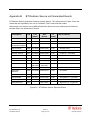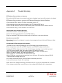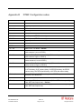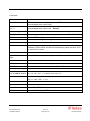
1
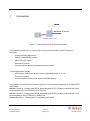
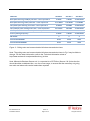
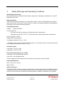
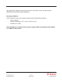
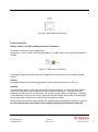
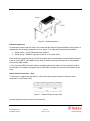
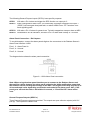
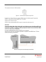
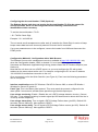
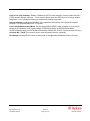
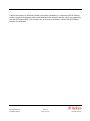
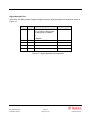
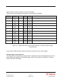
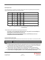
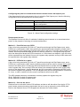
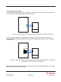
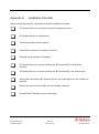
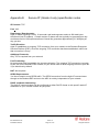
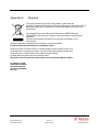
BT Redcare Secure Installation, Maintenance and Operational Manual Model UC-351 GP/E-UK Information for installers TABLE OF CONTENTS 1 INTRODUCTION .................................................................................................................. 3 2 PARTS LIST ......................................................................................................................... 5 3 SAFETY WARNINGS AND OPERATING CONDITIONS ..................................................... 6 4 MOUNTING AND WIRING ................................................................................................... 8 5 PIN POLARITY LEARNING ............................................................................................... 14 6 CONFIGURING THE REDCARE SECURE UNIT ............................................................... 15 7 NETWORK REGISTRATION AND COMMISSIONING....................................................... 22 8 MAINTENANCE AND OPERATIONS ................................................................................ 30 9. SUPPORT CONTACT DETAILS ........................................................................................ 31 APPENDIX A INSTALLATION CHECKLIST ......................................................................... 32 APPENDIX B BT REDCARE SECURE UNIT GENERATED EVENTS .................................. 33 APPENDIX C TROUBLE SHOOTING ................................................................................... 34 APPENDIX D DTMF CONFIGURATION CODES .................................................................. 35 APPENDIX E SECURE IP (GRADE 4 ONLY) SPECIFICATION NOTES .............................. 37 APPENDIX F DISPOSAL ...................................................................................................... 38 APPENDIX G ABBREVIATIONS ........................................................................................... 39 APPENDIX H REGULATORY APPROVALS......................................................................... 40 BT Redcare Secure Issue 16 Installation Manual Page 2 of 40 June 2010 All rights reserved 1 Introduction GPRS Ethernet or PSTN Redcare Secure unit Figure 1 – Redcare Secure Security Communicator The Redcare Secure unit is a multi-function security communicator from BT Redcare. It combines: - Alarm panel dial capture unit - Cellular (GSM-GPRS) modem - 0800 PSTN (IP) uplink - Ethernet (IP) uplink - General-purpose alarm and status inputs and outputs Typical applications include: - Commercial / Residential alarm systems (Signalling grades 2, 3 or 4) - Fire alarm systems - Consumer alarm systems that require dual path delivery The Redcare Secure unit can be used in any one of the following configurations. (Redcare ESP dependant) Secure 2 Grade 2 - Primary path GPRS, Secondary path PSTN (Voltage monitored with 1008 hour heartbeat, 24 hour PSTN call on GPRS Fail) Secure 3 Grade 3 - Primary path GPRS, Secondary path PSTN (Voltage monitored with 1008 hour heartbeat, 4 hour PSTN call on GPRS Fail) Secure IP Grade 4 - Primary path IP, secondary path GPRS. BT Redcare Secure Issue 16 Installation Manual Page 3 of 40 June 2010 All rights reserved PRODUCT SECURE 2 SECURE 3 SECURE IP 2 MINS 2 MINS 70 SECONDS Both paths working, Radio path fails – fault reported in 5-55 MINS 5-55 MINS 3-13 MINS Only Radio path working and it fails – fault reported in 55 MINS 55 MINS 70 SECONDS 25 HOURS 5 HOURS 70 SECONDS If both paths failed simultaneously – fault reported in 55 MINS 55 MINS 13 MINS Primary Polling Frequency 5 MINS 5 MINS 10 SECONDS 2 3 4 ATS VALUE PRIMARY ATS4 ATS4 ATS5 ATS VALUE SECONDARY ATS3 ATS4 ATS4 Both paths working, PSTN/IP path fails – fault reported in Only PSTN/IP path working and it fails – fault reported in EN GRADE Figure 2 - Polling rates and communication fail alarm transmission times Note: The polling rates and communication fail alarm transmission times in Fig 2 may be liable to change. For the latest information, refer to the Technical information sheet at http://www.redcare.bt.com/partner/brochure_list.htm Note: Where the Redcare Secure unit is connected to a PSTN line (Secure 2 & 3) then the line should be either a dedicated line, or a line of low usage, to ensure that the necessary out going test calls and alarm calls can be made when required. BT Redcare Secure Issue 16 Installation Manual Page 4 of 40 June 2010 All rights reserved 2 Parts List The BT Redcare Secure Unit is shipped with the following items: - BT Redcare Secure unit (Blue PCB) - Adhesive pads - Antenna - SIM card (fitted) The following are required in order to complete the Redcare Secure installation: General hand tools (2mm blade screwdriver, wire cutters, etc) Connection cable ADSL filter (Secure 2&3 only) for PSTN broadband lines BT Redcare Secure Issue 16 Installation Manual Page 5 of 40 June 2010 All rights reserved 3 Safety Warnings and Operating Conditions Qualified Personnel Only Only qualified service personnel should install, and perform subsequent maintenance on the BT Redcare Secure Unit. Battery Handling Take care not to short the battery in the host alarm system. A short-circuited battery can deliver large currents that could result in serious burns or create a fire hazard. Dispose of used batteries according to local environmental regulations. Power Requirements Voltage: 9VDC to 30VDC * Current: @ 13.8V: - Pin only mode 230mA quiescent, 280mA peak alarm transmission. - Dial capture mode (SIA / CID / FF) 270mA quiescent, 450mA peak alarm transmission. Current: @ 24V = 170mA Ripple/noise: 200mVpp max. Low battery threshold: 10.2V +/- 0.5V. * The Secure unit can be used with 24V volt systems, i.e Fire Alarm panels, but be aware that the low voltage threshold alarm is fixed at 10.2V. Pin Alarm Inputs Logic High = +3.5V to +30V Logic Low = -0.5V to +0.8V General Purpose Outputs: (on J1400) Logic High = 12V (nominal) @ 1mA max Logic Low = 0.4V @ 200mA max These voltages are with respect to the 0V terminal on the Power Connector J800. Physical Dimensions Size = 168 x 115 x 36 mm Mass = 500 g SELV Connectors Connectors J1300, J1301 (pin inputs) J1400 (outputs), J1000 (alarm panel), J600 (Ethernet) and J 800 (DC power) have been classified as SELV and must only be connected to approved SELV circuits. If the circuit to be connected to these terminals is not SELV an isolation unit compliant BT Redcare Secure Issue 16 Installation Manual Page 6 of 40 June 2010 All rights reserved with local market regulatory requirements must be used. SELV circuits are determined in IEC60950 and equivalent national standards. Operating Conditions The BT Redcare Secure unit is rated to operate under the following conditions: - Indoor operation - Ambient temperature: -5oC (23oF) to +55oC (131oF) - Humidity: 5% to 95% Note: BT Redcare recommend using a power supply capable of providing at least 450mA at 13.8VDC for this product. BT Redcare Secure Issue 16 Installation Manual Page 7 of 40 June 2010 All rights reserved 4 Mounting and Wiring Figure 3 - BT Redcare Secure unit connections BT Redcare Secure LED functions: Power - Supply voltage indicator Wireline - Wireline (PSTN or Ethernet) status indicator Wireless - GPRS status indicator SS1, SS2 - Wireless Signal Strength indicators Security - 1 blink = new input event detected Ethernet - Data present on RJ45 BT Redcare Secure Issue 16 Installation Manual Page 8 of 40 June 2010 All rights reserved Selecting the Mounting Location When surveying the site, please remember that the Redcare Secure unit operates in a similar way to an ordinary mobile telephone. Therefore any restrictions on the use of mobile telephones in the area will also apply to the Redcare Secure unit. Premises such as hospitals, petrol stations, airports, blasting areas etc may operate a mobile telephone restriction in certain areas. Always ensure that the chosen site is free of any mobile telephone restrictions and advise the end user so that they are aware, should any restrictions come into force in the future. If possible, perform a signal strength test during a pre-installation site visit. To perform a GSM signal strength test: 1. Determine where the Redcare Secure unit will be situated 2. Place the test mobile phone where the Redcare Secure unit is to be installed, switch it on and observe the signal strength from the Vodaphone network. If the signal strength is weak, try to find a better position for the Redcare Secure unit. If required, extension antennas and extension cables are available. Please contact 08702 400503 for further advice. Install away from any other Radio sources. Keep at least a 3 metre separation. Mounting the Redcare Secure unit Important: Ensure the alarm system is powered down (switch off mains and disconnect the battery) before installation can commence. Ensure that the base of the Redcare Secure unit is free from dust or grease. Use the supplied double sided mounting pads to fit the Redcare Secure unit onto a clean, flat surface within the host enclosure, or in its own tamper-protected box. PSTN connection (Secure 2 & Secure 3 / Grade 2 & 3 only) Connect 2 wires A & B from a suitable PSTN telephone line to J400. Line polarity is not important. Ethernet Connection. (Secure IP / Grade 4 only) Run an Ethernet cable from a convenient network connection to the Redcare Secure unit‟s Ethernet connector, J600. The Ethernet port auto-senses, so that either a straight-through or cross-over Ethernet cable can be used. Only ready-made, certified cables should be used when connecting the redcare Secure unit to network equipment. If cabling has to be made on site then testing and certification to EN 50173 Class D should be performed. Failure to use certified network cabling can lead to intermittent and spurious faults that are difficult to trace without specialist equipment. BT Redcare Secure Issue 16 Installation Manual Page 9 of 40 June 2010 All rights reserved Figure 4 - J600 Ethernet connection Power Connection Ensure power is off when cabling the power connectors. The power connection is via terminal J800. Connect the +12V or +24V to the terminal labelled + of J800, and 0V to the terminal labelled 0V of J800. Figure 5 - J800 power connection The power wiring must be less than 3m in length and use wires having core areas of at least 0.5mm2. Tamper If an additional tamper connection is required, connect the tamper switch to GPIP 12. Antenna The antenna provided is a flat type and must be mounted indoors, on a flat horizontal surface, sufficiently close that it can be connected to the Redcare Secure unit. The antenna is selfadhesive and will bond firmly to any clean, dry and flat surface. Make a suitable hole, (typically 11mm diameter) in the top of the box in which the Redcare Secure unit is fitted. Prevent swarf from entering the enclosure as it could cause internal short circuits. Remove any burrs from the hole, pass the RF cable through it and place the antenna in position. Do not permanently fix the antenna until a Signal Strength Test has been performed. BT Redcare Secure Issue 16 Installation Manual Page 10 of 40 June 2010 All rights reserved Figure 6 - Antenna position Extension Antenna An extension antenna can be used in the event that the Receive Signal strength at the location is inadequate, and changing locations is not an option. Two high gain antennas are available: 1. Aerial (short) – AO100 External base antenna 2. Aerial (long) – BA900-5 High gain antenna (1.2m white stick) Each antenna is supplied with a 5 m RG 58 coaxial cable terminated by a female FME connector. A 20 cm male FME to male MMCX flying lead is used to terminate the antenna on the Redcare Secure unit GSM module. A 10 m low-loss URM 76 coaxial cable is available should the cable run to the antenna need to be extended. This cable is equipped with a male FME connector at one end and a female at the other. Alarm Panel Connection – Pins To interface to a panel with pin alarms, connect the alarm panel outputs to the alarm input terminals on J1300 and J1301. Figure 7 - General Purpose Input Pins Unused input terminals can be left unconnected. BT Redcare Secure Issue 16 Installation Manual Page 11 of 40 June 2010 All rights reserved The following General Purpose inputs (GPIP‟s) have specific purposes: GPIP4 Will raise a Pin 4 alarm and trigger the RPS function on output pin 3. GPIP11 When configured for BSIA Form 175 functionality, activates a response on output 1 (GPOP1) to interrogate local path fault, or raises a BSIA Form 175 Test alarm over each signalling path. GPIP12 Will raise a Pin 12 alarm for general use. Typically mapped as a tamper alarm at ARC. GPIP13 Dedicated for AC fail indication, will raise a Pin 13 alarm after a delay of 7 minutes. Alarm Panel Connection – Dial Capture To use dial-capture, connect the alarm panels digicom line connectors to the Redcare Secure‟s Alarm Panel interface J1000. Pins 1, 2 - Alarm Panel In Pins 3, 4 - Unused Pins 5, 6 - Unused The diagram below shows the alarm panel connection. Figure 8 - J1000 Alarm Panel connection Note: When using the alarm panel interface port to connect to the Redcare Secure unit, there will be a delay between the alarm panel activating the dialler notification output and the Redcare Secure sending the message to the ARC. The length of the delay may be up to 20 seconds and varies depending on the make and model of the alarm panel. Also, if the panel goes off-hook but fails to dial within 10 seconds, a “Panel Dial fail” alarm will be sent. General Purpose Outputs (GPOP’s) Three General Purpose outputs are provided. The outputs are open collector outputs (with 12V pull-up). The outputs are rated to 30V. BT Redcare Secure Issue 16 Installation Manual Page 12 of 40 June 2010 All rights reserved The outputs are wired to J1400 as shown. Figure 9 - J1400 General Purpose Output Pins By default, the General Purpose outputs (GPOP‟s) have the following specific purposes: GPOP1: Local path fault output (BSIA Form 175 mode) GPOP2: ARC controlled output GPOP3: Return path signalling (RPS) output (in conjunction with input pin 4) WARNING Connectors J600, J800, J1000, J1300, J1301 and J1400 have been classified as SELV and shall only be connected to approved SELV circuits. If the circuit to be connected to these terminals is not SELV, a regulatory authority compliant isolation unit must be used. SELV circuits are determined in IEC60950. For basic installations the wiring of GPOP‟s is not required. Where local comms fail reporting is required in compliance with BSIA form 175 then make the following connections. BT Redcare Secure Issue 16 Installation Manual Page 13 of 40 June 2010 All rights reserved 5 Pin Polarity Learning The Redcare Secure unit can be forced to learn the polarity of the pin alarm inputs as follows. 1. Short out the Learn header J902 with a link. 2. Power up or power-cycle the unit. 3. Wait around 15 seconds until the LED‟s flash in the “learn ready” pattern (left to right scrolling pattern). 4. Connect all 16 pin inputs in the Normal state (including input 4 as closed state). Note: If pin 12 is used for Tamper it must also be connected in its normal (closed) state, even though the enclosure may actually be open 5. Remove the header from J902. The unit will briefly flash all LED‟s off-on-off to indicate learning has completed and will store this information in non-volatile memory. The boot sequence will then continue. Note: If the polarity of a pin (or pins) needs to be changed, the above procedure should be repeated, with the relevant pins connected in the Altered State at stage 4. BT Redcare Secure Issue 16 Installation Manual Page 14 of 40 June 2010 All rights reserved 6 Configuring the Redcare Secure unit The unit is supplied pre configured for pin only input mode and PSTN working. (Secure 2 / Secure 3) For most installations no further configuration will be required. For alternative installation requirements the following configuration options are available. There are two methods available to configure the unit. It can be configured with either a DTMF phone or through a web console on a PC internet browser. Configuration Method 1. Configuring with a DTMF Phone 1. Prepare wiring as described in Section 4. 2. For initial power-up and configuration, the following minimum connections are required: a. DC Power b. Antenna (for wireless operation) 3 Connect a DTMF phone to the units‟s alarm panel port J1000. An adapter is available from BT Redcare. See fig 10 4 Short out the Config header J903 with a link. 5 Power up or power-cycle the unit. 6 Around 15 seconds after power on, the six rightmost LED‟s will flash providing a period of 20 seconds to lift the telephone receiver, receive dial tone and press the '#' key to enter configuration Mode. Note: Configuration Mode is terminated after five minutes, or when the installer hangs-up the DTMF phone. Note: If the Config header is left shorted once configuration mode is completed the unit will not dialup or communicate at all. Figure 10 – Adapter to connect a DTMF telephone to J1000 for configuration. BT Redcare Secure Issue 16 Installation Manual Page 15 of 40 June 2010 All rights reserved Configuring Panel Format By default the unit is configured for pin-only mode. This mode disables the dial capture port to reduce power consumption. Use the following command to enable the dial capture port and set it to receive the relevant panel format where dial capture is required. Note Pins can still be reported in any of these other modes. To change the panel format, use the * 15 * option: * 15 * 1 # ContactID * 15 * 10 # High Speed (fast format) * 15 * 20 # SIA * 15 * 30 # Pin Only mode - default The Redcare Secure unit supports several other less common formats listed below: * 15 * 2 # ContactID with Double Knock * 15 * 3 # 4 + 1 express (DTMF mode only) * 15 * 5 # 4 + 2 express (DTMF mode only) * 15 * 11 # High Speed with Double Knock * 15 * 21 # SIA with V21 tones If no more parameters are to be configured, remove the header from J903 and disconnect the DTMF phone. Configuring General Purpose Outputs By default, the Redcare Secure unit‟s General Purpose Outputs (GPOP‟s) operate as follows: Output GPOP1 Default Function Local path fail output GPOP2 Remotely (ARC) Controlled GPOP3 RPS function (in conjunction with input pin 4) Default Polarity High to indicate dual path failure. 0 from ARC sets output High, 1 from ARC sets output Low Alarm sent sets output High, Alarm ack‟d sets output Low Figure 11 - General Purpose Output Pin operations The following commands can be used to configure the behaviour of the GP Outputs: GPOP1 * 91 * 20 * 91 * 30 BSIA Form 175 Mode – default mode Standard Path Fail Mode Active Low (Failure of any communications path causes a Low on GPOP1) BT Redcare Secure Issue 16 Installation Manual Page 16 of 40 June 2010 All rights reserved * 91 * 31 Standard Path Fail Mode Active High (Failure of any communications path causes a High on GPOP1) * 91 * 50 Standard Path Fail Mode 2 Active Low (Failure of both communications paths causes a Low on GPOP1) * 91 * 51 Standard Path Fail Mode 2 Active High (Failure of both communications paths causes a High on GPOP1) GPOP2 * 92 * 10 Remotely (ARC) Controlled Active Low (0 from ARC sets output High, 1 from ARC sets output Low) – default mode * 92 * 11 Remotely (ARC) Controlled Active High (1 from ARC sets output High, 0 from ARC sets output Low) GPOP3 * 93 * 10 RPS function Active Low (Alarm sent on GPIP4 sets output Low, Alarm acknowledged sets output High) * 93 * 11 RPS function (Alarm sent on GPIP4 sets output High, Alarm acknowledged sets output Low) – default mode Note: GPOP3 is used, in conjunction with GPIP4, for Return Path Signalling (RPS). On receiving an indication on GPIP4 (i.e. an opening or closing signal), the unit sets GPOP3. On receiving the ACK from the ESP, the unit clears GPOP3. If no more parameters are to be configured, remove the header from J903 and disconnect the DTMF phone. Configuring PSTN Pre-Dial String The unit is default configured with a pre-dial string of 1470 to provide CLI. If a pre-dial string is present, a 1 second pause is automatically added before the main phone number. Additional pauses may be added within the dial string using *0, an asterisk may be added using *1, and a hash may be added using *2 Examples of some Pre-dial configurations. *50*9# (Featureline or CLI enabled PABX line) *50*91470# (For a silent PABX line) *50*9*01470# *50*1470# *50*# (For a silent PABX line with pause) (default setting) (Clear predial string) BT Redcare Secure Issue 16 Installation Manual Page 17 of 40 June 2010 All rights reserved Configuring the Account Number / TAID (Optional) The Redcare Secure unit does not require its Account Number TA ID to be entered for normal operation, but it can be configured with the following command to aid identification where necessary. To set the Account Number / TA ID * 20 * TAID # Check Digit Example * 20 * 4191000 # 1 The unit sends a soft acceptance tone after each „#‟ and after the Check Digit. A series of sharp beeps means data has been incorrectly entered. Re-enter the full command. If no more parameters are to be configured, remove the header from J903 and disconnect the DTMF phone. Configuration Method 2. Configuration with a Web Browser The Redcare Secure unit‟s management console is available at http://192.168.222.222/, only when the Configuration header, J903, is shorted. If it is not possible to connect using the Username and Password supplied during training, please contact the BT Redcare Helpline (see Section 8). Note that the unit does not run a DHCP server, so you must configure the PC with a static address on the same subnet as the unit. For example, configuring the PC to have IP address 192.168.222.10 would allow connection to the unit. Once connected, surf to the Quick Start link (see Figure 9). From here the following parameters can be configured: Interface combination select GP Wireless / Dial UP for Secure 2&3, or select GE Wireline / Wireless for Secure IP (grade 4) Panel Type This is the alarm panel protocol. This must match the protocol configured in the alarm panel if connected to a dialler alarm panel through the dial capture port. Line voltage monitoring. Enable / Disable the unit‟s PSTN voltage detection circuitry. (Secure 2&3 only – Line voltage monitoring is used to signal pin 955 alarms and to detect when the line is in use by another telephone) Line voltage alarm delay. Time to signal a PSTN Voltage Failure alarm (pin 955). Default 120 seconds. (Secure 2&3 only). Also applies to GPOP1 Line voltage restore delay. Time to signal a PSTN Voltage Failure restore (pin 955). Default 30 seconds. (Secure 2&3 only). Also applies to GPOP1 BT Redcare Secure Issue 16 Installation Manual Page 18 of 40 June 2010 All rights reserved Line in use (LIU) Indicator. Enable / Disable the PSTN voice detection circuitry within the unit‟s PSTN modem (Secure 2&3 only – LIU is used to detect when the PSTN line is in use by another telephone. If Line Voltage monitoring is enabled this setting is ignored) Output Settings including the definition of the operation and polarity of the General Purpose Outputs (1-3). (Default BSIA form 175 mode) Line Fault Debounce time (Mins). Set the delay before GPOP1 state changes. t1,t2,t3,t4,t5,t6. Where t1=IP fail delay, t2=IP restore delay, t3=GPRS fail delay, t4=GPRS restore delay, t5=PSTN dial fail delay, t6=PSTN dial restore delay. Default 2,0,15,0,15,0 (S/W Version >52 only) Account Nbr / TA ID This number can be used to identify the site. (optional) IP Settings including DHCP Client or static local IP and gateway addresses (Secure IP only). BT Redcare Secure Issue 16 Installation Manual Page 19 of 40 June 2010 All rights reserved Figure 12 - Screenshot of the Quick Start Menu when set for PSTN working On completion of the configuration, click the “Save/Reboot” button at the bottom of the screen and remove the header from J903. Wait 1 minute for the save re-boot process to complete. BT Redcare Secure Issue 16 Installation Manual Page 20 of 40 June 2010 All rights reserved Figure 13 -.Screenshot of the Quick Start menu when set for IP working. BT Redcare Secure Issue 16 Installation Manual Page 21 of 40 June 2010 All rights reserved 7 Network Registration and Commissioning Ensure both Config and learn headers are removed. If Config Header (J903) is shorted, the unit will not attempt to register on the BT Redcare Enterprise Service Platform (ESP). The header short should be removed once configuration is complete. Network Registration On startup, the unit will immediately attempt to register on the BT Redcare ESP with all available interfaces: - GPRS - PSTN or Ethernet During registration and also in normal operation, the meaning of the LED indications is as follows: State Off Wireline (LED 2) Wireless (LED 3) Either: Either: The unit is in the process of starting up The unit is attempting to obtain an IP address or: The wireline path is not available. i.e. Ethernet port cannot obtain an IP address or PSTN path was unable to complete the last dial up attempt) Slow Flash 1s Off 1s On Fast Flash 250ms Off 250ms On Blink 50ms On 950ms Off On or: The wireless interface is not available The Unit is attempting to set up an IP path to the ESP. (i.e. Ethernet port has obtained an IP address and is attempting to reach the ESP. Or PSTN is attempting to establish a dial up call) The unit has an IP address over its wireless (i.e. GPRS) interface and is attempting to contact the ESP PSTN path has a call in progress and is communicating with the ESP N/A PSTN path has detected PSTN voltage fail < 1.5V on PSTN N/A The unit is connected to the BT Redcare ESP via IP, or the last PSTN dial up call was successful. The unit is connected to the BT Redcare ESP via GPRS Figure 14 - Wireline and Wireless LED indications BT Redcare Secure Issue 16 Installation Manual Page 22 of 40 June 2010 All rights reserved If either the Wireline or Wireless network connection is available (i.e. respective LED is flashing slowly), but does not become solid or fast flashing for 30 seconds, then the unit is not registering with the BT Redcare ESP. This could be due to an error in activation. Contact the BT Redcare Helpline for assistance. BT Redcare Secure Issue 16 Installation Manual Page 23 of 40 June 2010 All rights reserved Signal Strength Test LEDs SS1 and SS2 provide a signal strength indication. Signal strength is indicated as shown in Figure 15 SS2 SS1 Signal Strength Quality Off Off No reading available (e.g. modem is being reset or attempting to register) Unacceptable or Off <-89dBm FLASH -89dBm to -83dBm Boarderline Off On -83dBm to –77dbm Good FLASH On -77dBm to -69dBm Very Good On On > -69dBm Excellent Figure 15 - Signal Strength LED indications BT Redcare Secure Issue 16 Installation Manual Page 24 of 40 June 2010 All rights reserved Commissioning Once the unit is registered with the BT Redcare ESP, perform the following steps: 1. Ensure the unit is connected to the network. 2. Power cycle the unit to begin the commissioning process (both headers off). 3. After 1 minute the unit will begin establishing its communication paths. 4. After a further 1 minute, LEDs 2 & 3 should be permanently lit to show that the Wireline & Wireless paths are both available. Note that the rightmost LED (Power indicator) is LED 1. Time hh:mm:ss 10:00:00 Path Indicator 0x13 Pin 1023;0 10:00:03 0x13 or 23 984;1 10:00:04 0x13 or 23 984;3 10:00:11 0x23 1022;0 CID (zone) R350 (999) E305 (995) R305 (995) R350 (998) SIA (zone) NR (999) AT (995) AR (995) NR (998) Description Wireline Path communications restore Unit restarted (power up cycle) event Unit restarted (power up cycle) restore Wireless Path communications restore Figure 16 – Typical ARC alarm log for Redcare Secure unit initial commission Note that the unit sends a “Unit Restart” alarm / Restore cycle over the first available interface if the power to the unit has been interrupted. (0x13 indicates Wireline path, 0x23 indicates Wireless path). Test alarms can now be generated. If the unit is configured for BSIA 175 working, briefly apply an alarm condition to pin input 11. Within 1 minute a pin 988 event & restore should be received at the ARC over both paths. This test proves that both paths are signalling correctly. Note that if both paths are not available, no alarm will be received by the ARC. Time hh:mm:ss 10:05:00 Path Indicator 0x13 Pin 988;1 10:05:02 0x23 988;1 10:05:02 0x13 988;3 10:05:03 0x23 988;3 CID (zone) E354 (997) E354 (997) R354 (997) R354 (997) SIA (zone) TX (999) TX (998) TE (999) TE (998) Description BSIA 175 IP Test message event (IP) BSIA 175 GPRS Test message event (GPRS) BSIA 175 IP Test message restore (IP) BSIA 175 GPRS Test message restore (GPRS) Figure 17 - Typical ARC alarm log for Redcare Secure unit BSIA Form 175 path test BT Redcare Secure Issue 16 Installation Manual Page 25 of 40 June 2010 All rights reserved Apply an alarm / restore condition to all used input pins. These events will be signalled immediately over GPRS path if available. Time hh:mm:ss 10:07:00 10:08:00 10:09:00 10:09:30 10:10:00 10:10:02 10:10:03 10:10:04 10:15:00 10:15:10 Path Indicator 0x13 or 0x23 0x13 or 0x23 0x13 or 0x23 0x13 or 0x23 0x13 or 0x23 0x13 or 0x23 0x13 or 0x23 0x13 or 0x23 0x13 or 0x23 0x13 or 0x23 Pin 4;3 2;1 3;1 7;1 4;1 2;3 3;3 7;3 12;1 12;3 CID (zone) R323 (904) E323 (902) E323 (903) E323 (907) E323 (904) R323 (902) R323 (903) R323 (907) E323 (912) R323 (912) SIA (zone) UR (904) UA (902) UA (903) UA (907) UA (904) UR (902) UR (903) UR (907) BA (912) BR (912) Description Pin 4 Close (panel set) Pin 2 panic alarm event Pin 3 intruder alarm event Pin 7 confirmed intruder alarm event Pin 4 Open (panel unset) Pin 2 panic alarm restore Pin 3 intruder alarm restore Pin 7 confirmed intruder alarm restore Pin 12 Tamper alarm Pin 12 Tamper alarm restore Figure 18 - Typical ARC alarm log for Redcare Secure unit test pin alarms during commissioning Check with the ARC that these alarms have been received over the relevant paths. Remote trigger of dual path test The ARC can send the telemetry command ID=01, Data=00 to cause the Redcare Secure unit to send a BSIA test message on all available paths. Within 70 seconds a pin 988 Event / Restore will be received via each path. BT Redcare Secure Issue 16 Installation Manual Page 26 of 40 June 2010 All rights reserved Dial Capture test If the alarm panel is connected to the Dial Capture port of the unit, generate panel test alarms / restores and confirm that they are received at ARC. Time hh:mm:ss 10:20:00 10:21:00 10:22:00 10:22:30 10:23:00 10:23:02 Path Indicator 0x13 or 0x23 0x13 or 0x23 0x13 or 0x23 0x13 or 0x23 0x13 or 0x23 0x13 or 0x23 CID (zone) R401 (001) E120 (001) E130 (002) E139 (001) E401 (001) R305 (000) SIA (zone) CL (001) HA (001) BA (002) BV (001) OP (001) OR (000) Description Panel Close (panel set) Panic alarm event Intruder alarm event Confirmed intruder alarm event Panel Open (panel unset) System Reset (panel reset) Figure 18 - Typical ARC alarm log for Redcare Secure dial capture alarms during commissioning Actual alarms will be dependant on panel type and protocol. If the ARC receives a Bad Panel Checksum Error, the panel is not transmitting in a format known to the BT Redcare Secure unit If the ARC receives a Panel Type Mismatch Error, the BT Redcare unit is not configured for the correct panel format. Communication fault testing Disconnect the wireline path connection and confirm that the correct alarm is received at the ARC Secure 2 & 3 Secure IP Pin 955 after 120 seconds, Restore after 30 seconds Pin 1023 after <60 seconds, restore after < 60 seconds Notes A PSTN voltage fail alarm (955) will be generated by the unit, and generally signalled over the GPRS path, if the PSTN voltage stays below 1.5V for 120s. A restore will be signalled after 30s of the PSTN voltage returning to normal. (Default settings) The transmission path of messages can be identified at the ARC by looking at the receiver number, generally within the raw message data. (13 = Wireline, 23 = GPRS). As a general rule, messages signalled on zones >900 are Redcare Secure unit generated events, whereas messages signalled on zones <900 are panel generated events. BT Redcare Secure Issue 16 Installation Manual Page 27 of 40 June 2010 All rights reserved Configuring the panel to communicate with the redcare Secure dial capture port If the alarm panel is being connected to the unit using the Dial Capture port, then the following configuration should be entered into the alarm panel: Call mode Reporting format Dialler Receiver number Account Number Static test call Single telephone number reporting CID / SIA / FF to match Redcare Secure units configuration 29 Last 4 or 6 digits of Secure unit TAID Daily Figure 19 - Alarm Panel configuration settings Remote panel access The Redcare Secure unit offers 3 methods of obtaining remote access to an associated alarm panel, for the purpose of carrying out remote maintenance. Method 1 – Panel Dial out over PSTN. If the unit is being used with CID, SIA or FF panel format through the Dial Capture port, and a PSTN line is connected to J400, then prefixing the panels downloader telephone number with 7 will operate the unit‟s bypass relay and allow the panel to dial out to a remote alarm installer‟s PC modem. Remote panel downloader access can then be carried out. The bypass relay will reset when the alarm panel drops the PSTN connection or if 30 minutes has elapsed. A pin 993 event will be reported when the redcare Secure unit‟s bypass relay operates, and a pin 993 restore will be reported when the bypass relay releases. Method 2 – PSTN dial in to panel. If the unit is being used with CID, SIA or FF panel format through the Dial Capture port, and a PSTN line is connected to J400, then the following method can be used for remote dial in panel access to the alarm panel. Contact the ARC and request them to operate the Redcare Secure units‟s bypass relay. An incoming PSTN call will then be routed through the unit‟s bypass relay and on to the alarm panel. A panel download, pin 993, event will be reported to the ARC at the time that the bypass relay operates. The unit‟s Bypass relay will remain operated for a maximum of 1 hour, or until a “switch to On-line mode” command is sent from the ARC. The ARC gateway telemetry commands to remotely operate the bypass relay are: ID=01, Data=02 to switch to bypass mode ID=00, Data=02 to switch to online mode Method 3 – Over the Air dial in. Redcare Secure units with Version P60 software and above will also allow Over the Air (OTA) panel remote access whereby a downloader link can be set up across the unit‟s GPRS path. Refer to the Redcare Secure OTA Supplement document for further details. BT Redcare Secure Issue 16 Installation Manual Page 28 of 40 June 2010 All rights reserved Connecting alarm pin inputs For alarm panels that provide „Positive applied‟ or „Positive removed‟ communicator outputs, the unit‟s input pins can be wired directly to the Alarm panel. Alarm panel Secure unit Figure 20 - Alarm panel with Positive Applied or Removed communicator outputs For alarm panels that have open collector communicator outputs (sometimes referred to as „Negative Applied‟ outputs) an additional 10K pull-up resistor will be required to be connected for each input pin. Alarm panel Aux 12V Secure unit 10K Resistors Figure 21 - Alarm panel with Open collector (Negative applied) communicator outputs with an additional 10K pull up resistor for each pin Note: Ensure the 0V of the alarm panel is Commoned to the 0V of the Redcare Secure unit when separate Power Supply Units are used. BT Redcare Secure Issue 16 Installation Manual Page 29 of 40 June 2010 All rights reserved 8 Maintenance and Operations The BT Redcare Secure is managed by the ESP servers and appropriate alarms are raised to alert the ARC to faults (see appendix B). This section describes the operational and maintenance activities that may be required. Internal Access The BT Redcare Secure unit is usually installed in a tamper monitored alarm system, so in general it is necessary to authorise yourself with the monitoring ARC before opening the unit. Once you have alerted the ARC: 1. Remove all watches, rings or other metal objects from your hands. 2. Use ESD protection. Unit Replacement To replace the unit, perform the following actions: 1. Switch off and disconnect the mains supply of the host alarm system. 2. Remove all watches, rings or other metal objects before opening the lid. 3. Disconnect and remove the battery of the host alarm system. 4. Mount the replacement unit and replace cable as per Section 4. 5. Reconnect the mains supply and switch on. 6. Contact the BT Redcare Helpline. The new unit serial number (SID) will need to be entered into the ESP by Redcare staff, to bring the new unit back into service. If a unit is being changed out for a SIM-less maintenance spare, then the SIM card must be removed from the failed unit and inserted into the replacement unit. Carry out this procedure as follows. 1. Power down the failed unit 2. Remove the 3 screws that secure the PCB to its plastic. 3. Remove the PCB 4. Remove the SIM card from the holder on the underside of the PCB 5. Write down the 20 digit SIM number as printed on the SIM card 6. Insert this SIM card into the holder on the replacement unit. 7. Connect up the replacement unit 8. Contact the BT Redcare Helpdesk and quote them the TA ID, Unit Serial Number (SID) and SIM number. BT Redcare Secure Issue 16 Installation Manual Page 30 of 40 June 2010 All rights reserved 9. Support Contact Details For assistance with your BT Redcare Secure installation, Contact the Redcare Helpdesk on 0800 671 240 option 5 BT Redcare Secure Issue 16 Installation Manual Page 31 of 40 June 2010 All rights reserved Appendix A Installation Checklist Before leaving the premises, complete the following Installation Checklist. BT Redcare Secure unit securely mounted in host alarm system. BT Redcare Secure unit powered up. Tamper connection wired if required. Configuration and learn link headers removed. Wireless signal strength is acceptable. BT Redcare Secure unit communicating with BT Redcare ESP over Wireless interface. BT Redcare Secure unit communicating with BT Redcare ESP over Wireline path. Alarm panel connected to BT Redcare Secure unit via dial-capture or pin interface as required. Alarms sent and received at ARC over all available interfaces. No Bad Panel Feed alarm events outstanding. BT Redcare Secure Issue 16 Installation Manual Page 32 of 40 June 2010 All rights reserved Appendix B BT Redcare Secure unit Generated Events BT Redcare Secure generates events for system alarms. The values listed in Figure 22 are the codes that are signalled by the unit in ContactID, Fast Format and SIA modes. Alarms sent over wireline can be differentiated from those sent over wireless by the Receiver Number field in the Automation Protocol. Description Pin CID (zone) SIA (zone) Low DC Input Level 985 302 (999) YT/YR 6 (2) E – Immediate; R – Immediate PSTN voltage fail 955 356 (999) LT/LR 6(5) E – 120s; R – 30s Bad Packet Count Threshold Exceeded 959 352 (999) ET/ER (999) 6 (3) E – Exceed Count; Bad Checksum 958 311 (999) ET/ER (993) 6 (3) E – Exceed Count; Missing Heartbeat 982 312 (999) ET/ER (991) 6 (3) E – 10 days; R – Immediate Off Hook Timeout 957 313 (999) ET/ER (989) 6 (3) E – 10 Min; R – Immediate Dial Fail 983 314 (999) ET/ER (987) 6 (3) E – 20 Sec; R – Immediate Runaway Panel 956 316 (999) ET/ER (983) 6 (3) E – 10 Min; R – Immediate Panel Disconnected 992 317 (999) ET/ER (981) 5 (1) E – 2 Min; R – Immediate GPIP1-16 1-16 323 (901-916) UA/UR (901-916) 7 (1) E – Immediate; R – Immediate Software Mismatch 979 304 (999) ET/ER (979) 6 (3) E – Immediate Panel Type Mismatch 989 311 (998) ET/ER (977) 6 (3) E – Immediate BSIA 175 Test 988 354 (997) TX/TE 6 (3) E – Immediate; R – Immediate Unit Restarted 984 305 (995) AT/AR (995) 5 (6) E – Immediate; R – Immediate Level 3 Access 978 627 (999) RB (999) 5 (3) E – Immediate Panel Download 993 LB/LX (999) FF Time to Active (zone) E – Bypass on; R – Bypass off Figure 22 - BT Redcare Secure Reported Events BT Redcare Secure Issue 16 Installation Manual Page 33 of 40 June 2010 All rights reserved Appendix C Trouble Shooting BT Redcare Secure does not start up Ensure that the DC power is connected, and that no headers have been left inserted on the board BT Redcare Secure doesn’t connect to BT Redcare Enterprise Service Platform Check that the DRN / Agency ID (Quikc start page) is set to “0” Check that the account has been activated in the BT Redcare ESP server. Check if this BT Redcare secure unit has already been connected under a different account. Check that the Config / Learn Headers are not shorted. Alarm panel does not break dial tone Check the connection to the alarm panel Check if the alarm panel has been set to DTMF dialling Plug in a standard DTMF phone and dial a digit to check that it can break dial tone No alarms sent to ARC Ensure that the panel is configured to report using a supported format (ContactID, Ademco High Speed, SIA). Unexpected PSTN Voltage fail (955) alarms. Test that the unit is correctly identifying the PSTN voltage using the following test. Enter configuration mode with a DTMF telephone. (see DTMF configuration section) To start the PSTN voltage test enter *59*, this will play a repeating sound until # is pressed. The LED scrolling pattern shall stop and the power LED shall be on solid. While running, the test shall display the PSTN line status on SS1 and SS2 LED‟s. With no PSTN line voltage, SS1 and SS2 shall be off. With a PSTN line connected SS1 and SS2 shall be solid. With a PSTN line connected and a premises phone off-hook, SS1 shall be solid and SS2 off. To end the PSTN voltage test key # Line voltage monitoring can be turned off where necessary with *52*0 It can be turned back on with *52*1 (default) Note: When Line voltage monitoring is turned on the Line in use (LIU) mechanism is overridden. If line voltage monitoring is turned off then no line voltage (955) alarms will be transmitted. BT Redcare Secure Issue 16 Installation Manual Page 34 of 40 June 2010 All rights reserved Appendix D DTMF Configuration codes Panel Format * 15 * 1 # Contact ID * 15 * 10 # High Speed (fast format) * 15 * 20 # SIA * 15 * 30 # Pin Only mode - Default * 15 * 2 # ContactID with Double Knock * 15 * 3 # 4 + 1 express (DTMF mode only) * 15 * 5 # 4 + 2 express (DTMF mode only) * 15 * 11 High Speed with Double Knock * 15 * 21 # SIA with V21 tones GPOP1 * 91 * 20 BSIA Form 175 Mode – Default * 91 * 30 Standard Path Fail Mode Active Low (Failure of any communications path causes a Low on GPOP1) * 91 * 31 Standard Path Fail Mode Active High (Failure of any communications path causes a High on GPOP1) * 91 * 50 Standard Path Fail Mode 2 Active Low (Failure of both communications paths causes a Low on GPOP1) * 91 * 51 Standard Path Fail Mode 2 Active High (Failure of both communications paths causes a High on GPOP1) *98*t1*t2*t3*t4*t5*t6# Where the following time delays apply to GPOP1 operation in mins 0-99 t1=IP fail delay, t2=IP restore delay, t3=GPRS fail delay, t4=GPRS restore delay, t5=PSTN dial fail delay, t6=PSTN dial restore delay * 98 * xx # (Up to S/W Version 52) Time delay before GPOP1 operates. xx=time in minutes 1-99. default=15 GPOP2 * 92 * 10 Remotely (ARC) Controlled Active Low (0 from ARC sets output High, 1 from ARC sets output Low) – Default * 92 * 11 Remotely (ARC) Controlled Active High (1 from ARC sets output High, 0 from ARC sets output Low) BT Redcare Secure Issue 16 Installation Manual Page 35 of 40 June 2010 All rights reserved Continued. GPOP3 * 93 * 10 RPS function Active Low (Alarm sent on GPIP4 sets output Low, Alarm acknowledged sets output High) * RPS function (Alarm sent on GPIP4 sets output High, Alarm acknowledged sets output Low) – Default 93 * 11 PSTN Voltage Mon *59* (# to end test) Line voltage test. State of line voltage is indicated on LED‟s SS1 & SS2 *52* 0 Disable PSTN voltage monitoring *52* 1 Enable PSTN voltage monitoring - Default PSTN Pre-Dial String *50* Predial No # Use *0 for a pause, *1 for a star, and *2 for a hash. Example *50*9*01470# will dial a 9 followed by a pause and then 1470 to ensure CLI is used TA Number * 20 * TAID # Check Digit Set the TA (Account) number. (Optional) - Example * 20 * 4191000 # 1 Panel Callback *17* X # Set the panel callback number (for panel remote access) to X. Default 7 *16* XX # Set the panel callback maximum time. Default 30 minutes IP Address settings *10* X*X*X*X#M*M*M*M # Set a static IP address X.X.X.X and subnet mask M.M.M.M *11* G*G*G*G # Set the Gateway address G.G.G.G Eg. *10* 192 * 168 * 1 * 10 # 255 * 255 * 255 * 0 # Eg *11* 192 * 168 * 1 * 1 # *13* 1 Switch back to DHCP mode. Default Interface Select *60* 1 Select IP + GPRS mode *60* 0 Select GPRS + Dialup PSTN mode. Default BT Redcare Secure Issue 16 Installation Manual Page 36 of 40 June 2010 All rights reserved Appendix E Secure IP (Grade 4 only) specification notes IP Protocol: TCP Port: 443 Data Usage / Requirements: Agile IP Grade 4 polling is every 10 seconds a poll and response results in 288 total bytes transferred (incl IP headers). A small number of alarms will also typically be generated per day and these result in 296 bytes transferred. Overall his generates approximately 2.5 M Bytes per day, per site. Traffic Direction: Agile IP establishes an outgoing TCP connection from your network to the Redcare Enterprise Services Platform (ESP). Once this outgoing TCP connection has been established, traffic over that connection is 2 way. Additional Protocols: Only TCP is required from your network. Port Forwarding: No ports need to be forwarded in the incoming direction. The outgoing TCP connection connects to port 443 on the Redcare ESP network, so you would need to allow outgoing access to port 443 if you block that by default. NAT: Not required: GPRS Requirements: You do not need to route GPRS traffic. The GPRS connection from the Agile IP communicator through to the Redcare ESP and on to the ARC is entirely independent of your network. DHCP and Static Addressing: The Agile IP communicators can be configured as either DHCP clients or with specific static IP addresses on your internal network as you prefer. BT Redcare Secure Issue 16 Installation Manual Page 37 of 40 June 2010 All rights reserved Appendix F Disposal The symbol shown here and on the product, means that the product is classed as Electrical or Electronic Equipment and should not be disposed of with other household or commercial waste at the end of its working life. The Waste Electrical and Electronic Equipment (WEEE) Directive (2002/96/EC) has been put in place to recycle products using the best available recovery and recycling techniques to minimise the impact on the environment, treat any hazardous substances and avoid the increasing landfill. Product disposal instructions for residential users: When you have no further use for it, please dispose of the product as per your local authority‟s recycling processes. For more information please contact your local authority or retailer where the product was purchased. Product disposal instructions for business users: Business users should return the product to the freepost address below: BT SUPPLY CHAIN DARLINGTON ROAD , NORTHALLERTON. NORTH YORKSHIRE DL6 2PJ. BT Redcare Secure Issue 16 Installation Manual Page 38 of 40 June 2010 All rights reserved Appendix G AC ACK ARC ATE BSIA Cat 5 CID dBm DC DHCP DTMF EN ESD ESP FF FME g GE-UK GP GPIP GPOP GPRS GSM IEC IP LAN LED M mA mm MMCX mVpp PC PCB RF RG RPS SELV SIA SIM SS TAID UC URM V VDC Abbreviations Alternating Current Acknowledgement Alarm Receiving Centre Alarm Transmission Equipment British Security Industry Association Category 5 cabling Contact Identification Decibel (referenced to milliwatts) Direct Current Dynamic Host Configuration Protocol Dual Tone Multi-Frequency European Norm Electrostatic Discharge Enterprise Service Platform Fast Format For Mobile Equipment gram GPRS + Ethernet (UK version) General Purpose General Purpose Input Pin General Purpose Output Pin General Packet Radio Service Global System for Mobile communication International Electrotechnical Commission Internet Protocol Local Area Network Light Emitting Diode metre milliamp millimetre Micro Miniature Connection millivolts peak-to-peak Personal Computer Printed Circuit Board Radio Frequency Radio Grade Return Path Signalling Safety Extra Low Voltage Signal Indicated Alarm Subscriber Information Module Signal Strength Terminal Adaptor Identification UltraConnect Uni-Radio-Metric Volts Volts (Direct Current) BT Redcare Secure Issue 16 Installation Manual Page 39 of 40 June 2010 All rights reserved Appendix H REGULATORY APPROVALS N13454 EN54-4:1997 LIABILITY The services and products provided by BT Redcare, when installed and commissioned, are only intended to provide a communications path between the equipment and a supervision centre to the extent that is reasonably practicable by use of such goods and services. DISCLAIMER The manufacturer or his agents disclaim responsibility for any damage, financial loss or injury caused to any equipment, property or persons resulting from any use of this equipment. The manufacturer is not liable for any purely economic loss arising from any use of this equipment. All responsibility and liability in the use of BT Redcare products are assumed by the user. This unit is designed to be used in customer premises. Use of this equipment in other locations may void warranty. This unit is not intended for use in marine environments or water borne vessels. BT Redcare may make changes to features and specifications at any time without prior notification in the interest of ongoing product development and improvement. BT Redcare Secure Issue 16 Installation Manual Page 40 of 40 June 2010 All rights reserved