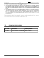
1
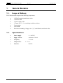
HT EV400 HITAG™ Proximity Evaluation Kit Product Description Revision 2.0 November 1996 Proximity Evaluation Description Rev. 2.0 November 1996 - is the name of one of the universal and powerful product lines of our 125 kHz family. The HITAG product family is used both in the proximity area (reading range up to about 200 mm) and in the long range area (reading range up to about 1000 mm). Developing our HITAG products, utmost consideration was given to security and reliability. The use of cryptography guarantees highest data security. Using optimized antennas and powerful transponders operating ranges of up to 1m can be achived. The central part of every HITAG Read/Write Device is the HITAG Core Module, which ensures full compatibility for every HITAG Read/Write Device. Easy integration and application of the HITAG Core Module is due to its: • small size • standard interfaces • flexible supply voltage To give you the possibility for an easy and quick start with our HITAG products we offer a HITAG Proximity Evaluation Kit. Easy application certainly is an important factor in making the Proximity Evaluation Kit suitable for evaluation purposes. You will be able to present your ideas and demonstrate the performance of your system with the help of the HITAG Evaluation Kit. If there are any questions please do not hesitate to contact us under +43 3124 / 299 - 281 (Mr. Kurt Bischof, Field Application Engineer). Htev400.doc/HS Page 2 of 43 November 1996 Rev. 2.0 Proximity Evaluation Description Proximity Evaluation Kit Description TABLE OF CONTENTS 1. General Remarks ....................................................................................................... 6 1.1. Scope of Delivery..........................................................................................................6 1.2. Specifications................................................................................................................6 1.3. Hardware Startup..........................................................................................................7 1.3.1. Housing ............................................................................................................7 1.3.2. Connecting the Read/Write Device to your PC and to the Power Supply ...........7 1.3.3. Connecting an external Antenna ........................................................................7 1.4. Software Startup ...........................................................................................................8 1.4.1. System Requirements ........................................................................................8 1.4.2. Installation ........................................................................................................8 1.4.3. Starting the Demo-Program ..............................................................................8 2. General Definitions for the Demo-Software ............................................................ 9 3. Mainmenu................................................................................................................. 10 3.1. Options .......................................................................................................................10 3.2. Transponder Type .......................................................................................................11 3.3. Help............................................................................................................................11 3.4. Quit ............................................................................................................................11 4. HITAG 1 Transponders ........................................................................................... 12 4.1. Memory Partitioning ...................................................................................................12 4.2. Operating HITAG 1 Transponders ..............................................................................14 4.3. Transponder................................................................................................................14 4.4. R/W-Device ................................................................................................................15 5. HITAG 2 Transponders ........................................................................................... 16 5.1. Memory Partitioning ...................................................................................................16 5.2. Crypto Mode ..............................................................................................................17 5.2.1. Transponder....................................................................................................17 5.2.2. R/W-Device ....................................................................................................18 5.3. Password Mode ..........................................................................................................19 5.3.1. Transponder....................................................................................................19 5.3.2. R/W-Device ....................................................................................................20 5.4. Public Mode A ............................................................................................................21 5.4.1. Transponder....................................................................................................21 5.4.2. R/W-Device ....................................................................................................22 5.5. Public Mode B ............................................................................................................23 5.5.1. Transponder....................................................................................................23 5.5.2. R/W-Device ....................................................................................................24 Page 3 of 43 Htev400.doc/HS Proximity Evaluation Description Rev. 2.0 November 1996 6. Transponders PCF793x (PIT) ................................................................................. 25 6.1. Memory Partitioning ...................................................................................................25 6.2. Operating PIT Transponders .......................................................................................26 6.3. Transponder................................................................................................................26 6.4. R/W-Device ................................................................................................................27 7. MIRO Transponders (µEM H400x).......................................................................... 28 7.1. Memory size ...............................................................................................................28 7.2. Operating MIRO Transponders ...................................................................................28 7.3. Transponder................................................................................................................28 7.4. R/W-Device ................................................................................................................29 8. Error Messages........................................................................................................ 30 9. Configuration of hitag™ Transponders ................................................................ 31 9.1. Security Mechanism ....................................................................................................31 9.2. HITAG 1 Transponders ..............................................................................................32 9.2.1. Read/Write Device ..........................................................................................32 9.2.2. Transponder....................................................................................................33 9.3. HITAG 2 Transponders ..............................................................................................34 9.3.1. Read/Write Device ..........................................................................................34 9.3.2. Transponder....................................................................................................35 10. Personalizing your Read/Write Device and the Transponders.......................... 36 10.1. General Definitions....................................................................................................37 10.1.1. HITAG 1 Transponders.................................................................................37 10.1.2. HITAG 2 Transponders.................................................................................39 10.2. Personalization Concept ............................................................................................40 10.3. Changing Keys and Passwords ..................................................................................40 10.3.1. HITAG 1 Transponders.................................................................................40 10.3.2. HITAG 2 Transponders.................................................................................42 11. Ordering Information............................................................................................. 43 Author : Ulrich Brändle Htev400.doc/HS Page 4 of 43 November 1996 Rev. 2.0 Proximity Evaluation Description Definitions Data sheet status Objective specification This data sheet contains target or goal specifications for product development. Preliminary specification This data sheet contains preliminary data; supplementary data may be published later. Product specification This data sheet contains final product specifications. Limiting values Limiting values given are in accordance with the Absolute Maximum Rating System (IEC 134). Stress above one or more of the limiting values may cause permanent damage to the device. These are stress ratings only and operation of the device at these or at any other conditions above those given in the Characteristics section of the specification is not implied. Exposure to limiting values for extended periods may affect device reliability. Application information Where application information is given, it is advisory and does not form part of the specification. Life support applications These products are not designed for use in life support appliances, devices, or systems where malfunction of these products can reasonably be expected to result in personal injury. Philips Semiconductors customers using or selling these products for use in such applications do so on their own risk and agree to fully indemnify Philips Semiconductors for any damages resulting from such improper use or sale. Page 5 of 43 Htev400.doc/HS Proximity Evaluation Description Rev. 2.0 1. General Remarks 1.1. Scope of Delivery November 1996 The Evaluation Kit comprises the following components: • • • • • • • 1.2. 1 HITAG proximity read/write device 1 Interface cable 1 Power supply cable 1 Floppy disc (3 ½") containing evaluation software Transponders User manual Data sheet containing 1 floppy disc (3 ½") with libraries and header files. Specifications • Power supply: 9 - 16 VDC • Supply current: maximum 150 mA • Frequency: 125 kHz • Temperature: • Interface: Htev400.doc/HS 0° - 70° C RS232 Page 6 of 43 November 1996 1.3. Rev. 2.0 Proximity Evaluation Description Hardware Startup Metallic environment and electromagnetic interferences (e.g.: monitors, keyboards) have a negative effect on the reading and writing range! 1.3.1. Housing H[WHUQDO DQWHQQD FRQQHFWRU 7$* GHWHFWHG 3RZHU $QWHQQD 3UR[LPLW\ (YDOXDWLRQ .LW 1.3.2. VHULDO ,QWHU IDFH SRZHU VXSSO\ FRQQHFWRU FRQQHFWRU Connecting the Read/Write Device to your PC and to the Power Supply Connect the supplied interface cable to the serial interface (COM1 or COM2) on your IBM compa-tible PC (286 or higher). Plug the power supply-cable into a power supply unit (9 - 16 VDC). 1.3.3. Connecting an external Antenna User derfined antennas may be connected at the external antenna connector. Concering the design of proximity antennas please please refer to the document HT RM400 (HITAG Core Module) resp. HT RM440 (HITAG Proximity Reader Module). Page 7 of 43 Htev400.doc/HS Proximity Evaluation Description Rev. 2.0 1.4. Software Startup 1.4.1. System Requirements November 1996 In order to use the RFIDDEMO-Software the following system requirements must be satisfied: • IBM-PC or compatible (minimum 286 processor) • 640 kbyte RAM • serial interface 1.4.2. Installation 1. Create a new directory on your PC for the Demo-Files (e.g.: C:\RFIDDEMO) 2. Copy all the files from the floppy disc into the directory you created in step 1. 1.4.3. Starting the Demo-Program Start your Demo-Program by typing the command RFIDDEMO.EXE. We strongly recommend to carefully read this description (especially chapters 9 and 10) before starting the Demo System! Inconsiderate use of individual menu options may result in unwanted irreversible changes in access rights. Htev400.doc/HS Page 8 of 43 November 1996 2. Rev. 2.0 Proximity Evaluation Description General Definitions for the Demo-Software • <ESC> quits a submenu. • Scrolling the menubar is done with the cursor keys ↑ and ↓. • <ALT F4> always quits the program. • <ENTER> chooses the submenu shown with ➨. • You can also use the hotkeys to select a submenu. • All menu items coloured in blue are not enabled in the software. • Upon starting the software checks which serial interface is used for communication with the read/write device. This may last for some seconds. • To increase the data reliability accessing transponders the software includes double read and read after write. Page 9 of 43 Htev400.doc/HS Proximity Evaluation Description 3. Rev. 2.0 November 1996 Mainmenu The two bottom lines display error messages, information about transponder, interface and read/write device. Status: Transponder: RW-Device: Cyclic 1ms: COM 2: 3.1. Displays error respectively status messages. Shows the chosen transponder (e.g.: HT2 Crypto) Gives information about the type of connected read/write device (Proximity or Long Range) Shows the mode of command repetition (Single or Cyclic access with delay time between end of first and beginning of the next command). See chapter 3.1 (Options Transponder Access). Shows the used serial interface (COM 1 or COM 2) Options Select Interface: Chooses the serial interface (COM 1 or COM 2). Transponder Access: Switches between single and periodically repeated commands. The specified value determines the time between the end of the first and the beginning of the next command. Sound Select: Enables a signal tone after successful read commands. Htev400.doc/HS Page 10 of 43 November 1996 3.2. Rev. 2.0 Transponder Type Auto: Initiates automatically transponder recognition (e.g.: HT2-Crypto) and pressing ENTER switches to the correct submenu. Please note: HT2 Public A transponders may also be recognized as MIRO transponders. To access HT2 Public A transponders use the proper submenu HT2-Public A. Provides access to HITAG 1 transponders. Chooses between the four modes of this transponder, Password, Crypto, Public A and Public B. Provides access to MIRO read only transponders. Provides access to PCF793x transponders. Hitag1: Hitag2: Miro: Pit: 3.3. Help System Overview: About: 3.4. Proximity Evaluation Description Gives a short overview on the 125kHz transponder system. Gives short information about the software. Quit Use this command to exit the Demonstration Program. Page 11 of 43 Htev400.doc/HS Proximity Evaluation Description Rev. 2.0 November 1996 4. HITAG 1 Transponders 4.1. Memory Partitioning The 2 KBit EEPROM memory on the transponder is divided into 16 blocks. Every block consists of 4 pages with 4 bytes (at 8 bits) each. Addressing is done page by page and access is gained either page by page or block by block entering the respective start address. In case of block read (or write) the transponder is processed from the start to the end of the block. The drawing below describes the memory configuration on the Demokit transponder: Block 0 Block 1 secret user data Block 4 secret*) user data r/w *) Block 7 Block 8 public user data ro r/w wo 0 r/w wo *) r/w *) read only read/write write only neither read nor write Configuration of the memory is done in the configuration page Block 15 *) public Serial Number Configuration Key A Key B secret Logdata 1B Logdata 0A Logdata 1A Logdata 0B Areas (or settings) marked with an asterisk *) may be configured by the client. The memory location described above and marked with an asterisk *) has been configured by Philips Semiconductors, whereby the content of some of the memory areas is free, some allocated. Block 0 defines the serial number, the configuration of the memory area and the keys, Block 1 the logdata. Memory locations marked with "secret" can only be accessed after a mutual authentication. An enciphered data communication is used in that area. Memory locations marked with "public" can be accessed without mutual authentication, no encryption is used. Htev400.doc/HS Page 12 of 43 November 1996 Rev. 2.0 Proximity Evaluation Description Transponders delivered with this Demokit are configured as follows: Blocks 4 to 7 of the transponder are public and read-write. The table shows that the logdata can be both written and read, keys can only be written. That means that keys and logdata can be changed. Important! You have to be very careful when changing keys and logdata as inconsiderate use results in loss of access to the secret area on the transponder. See Chapter 10 for a detailed description. Page 13 of 43 Htev400.doc/HS Proximity Evaluation Description 4.2. Rev. 2.0 November 1996 Operating HITAG 1 Transponders Operating a HITAG 1 transponder the screen will be displayed as follows: 4.3. Transponder Get ID: Get all ID:*) Read Page: Read all Page:*) Read Block: Write Page: Write Block: Reads the ID number of the transponder located in the field of the antenna. Reads the ID numbers of up to 10 transponders located in the field of the antenna. If more transponders are in the field, the total number is displayed in the bottom line of the window. On entering a page number (0-63) one page (4 bytes) of the transponder is read and displayed on the screen. On entering a page number (0-63) the content of one page (4 bytes) of up to 10 transponders is read and displayed on the screen. On entering a block number (0-15) and a page number (0-3) one block (up to 16 bytes) of the transponder is read and displayed on the screen. On entering a page number (8-63) and 4 bytes of numbers one page (4 bytes) is written to the transponder. On entering a block number (2-15), a page number (0-3) and up to 16 bytes of numbers one block (up to 16 bytes) is written to the transponder. Attention: You can only write cyclically on a TAG that is in the field when you initiate the write command. To write to another TAG please repeat the write command. Htev400.doc/HS Page 14 of 43 November 1996 Rev. 2.0 Personalization: Configuration: Proximity Evaluation Description Gives access to key and passwords stored on the transponder (TAG) (see also chapter 10) Submenu used to change the configuration of the transponder (see also chapter 9). *) The commands Get all ID and Read all Page are only enabled when using HITAG Long Range Read/Write Devices. 4.4. R/W-Device Personalization: Submenu to change keys and passwords of the read/write device. (refer to chapter 10) Configuration: Submenu used to change the configuration of the read/write device. (refer to chapter 9) KeyInit Password: Use this submenu to change the password for the configuration and personalization (see chapters 9 and 10). Get Version: Reads the version and programming date of the firmware and the serial number of the Core Module. Fast Fourier:*) This command starts the Fast Fourier Transformation (FFT) of the Digital Signal Processor. This command is to be used as often as required depending on the noisefloor of the environment. *) This command adjusts the timing of the read/write device to the antenna. Set BCD: The command has to be operated once, when an antenna is connected for the first time or changed. Reset System: Resets the read/write device and switches off high frequency for 100 ms. As a consequence the transponder in the antenna field is reset (e.g.: transponder that is in Halt Mode will respond again). *) The commands Fast Fourier and Set BCD are only enabled when using HITAG Long Range Read/Write Devices. Page 15 of 43 Htev400.doc/HS Proximity Evaluation Description Rev. 2.0 5. HITAG 2 Transponders 5.1. Memory Partitioning November 1996 The memory of the transponder (TAG) consists of 256 bits EEPROM and is organized in 8 pages with 32 bits each. The READ and WRITE instructions always read or write a whole page, and the address transmitted by the base station represents the page address. Depending on the mode of operation the EEPROM is organized in the following way: crypto mode: Page 0 1 2 3 4 5 6 7 Content ID number 32 bit Key: "KEY LOW" 16 bit Key " KEY HIGH" 8 bit Configuration, 24 bit Password TAG read/write Page read/write Page read/write Page read/write Page password mode: Page 0 1 2 3 4 5 6 7 Htev400.doc/HS Content ID number Password RWD reserved 8 bit Configuration, 24 bit Password TAG read/write Page read/write Page read/write Page read/write Page Page 16 of 43 November 1996 5.2. Rev. 2.0 Proximity Evaluation Description Crypto Mode Operating a HITAG 2 transponder in crypto mode the screen will be displayed as follows: 5.2.1. Transponder Get ID: Read Page: Write Page: Personalization: Configuration: Reads the ID number of the transponder located in the field of the antenna. On entering a page number (0-7) one page of the transponder is read and displayed on the screen. On entering a page number (4-7) and 4 bytes of numbers one page is written to the transponder. Gives access to the key and password stored on the transponder (TAG). • Key is used to encrypt the data sent to and received from the transponder. • Password TAG is sent from transponder to read/write device and can be verified by the latter depending on the configuration of the read/write device (see also chapter 10) Submenu used to change the configuration of the transponder. (see also chapter 9) Attention: You can only write cyclically on a TAG that is in the field when you initiate the write command. To write to another TAG please repeat the write command. Page 17 of 43 Htev400.doc/HS Proximity Evaluation Description Rev. 2.0 November 1996 5.2.2.R/W-Device Personalization: Submenu to change keys and passwords of the read/write device. (see also chapter 10) Configuration: Submenu used to change the configuration of the read/write device. (see also chapter 9) KeyInit Password: Use this submenu to change the password for the configuration and personalization (see chapter 9 and 10). Get Version: Reads the version and programming date of the firmware and the serial number of the Core Module. Fast Fourier:*) This command starts the Fast Fourier Transformation (FFT) of the Digital Signal Processor. This command is to be used as often as required depending on the noisefloor of the environment. *) This command adjusts the timing of the read/write device to the antenna. Set BCD: The command has to be operated once, when an antenna is connected for the first time or changed. Reset System: Resets the read/write device and switches off high frequency for 100 ms. As a consequence the transponder in the antenna field is reset (e.g.: transponder that is in Halt Mode will respond again). *) The commands Fast Fourier and Set BCD are only enabled when using HITAG Long Range read/write devices. Htev400.doc/HS Page 18 of 43 November 1996 5.3. Rev. 2.0 Proximity Evaluation Description Password Mode Operating a HITAG 2 transponder in password mode the screen will be displayed as follows: 5.3.1. Transponder Get ID: Read Page: Write Page: Personalization: Configuration: Reads the ID number of the transponder located in the field of the antenna. On entering a page number (0-7) one page of the transponder is read and displayed on the screen. On entering a page number (4-7) and 4 bytes of numbers one page is written to the transponder. Gives access to the two passwords stored in the transponder (TAG). (see also chapter 10) • Password RWD is sent from read/write device to transponder and checked for identity by the latter • Password TAG is sent from transponder to read/write device and can be verified by the latter depending on the configuration of the read/write device. Submenu used to change the configuration of the transponder. (see also chapter 9) Attention: You can only write cyclically on a TAG that is in the field when you initiate the write command. To write to another TAG please repeat the write command. Page 19 of 43 Htev400.doc/HS Proximity Evaluation Description Rev. 2.0 November 1996 5.3.2.R/W-Device Personalization: Submenu to change keys and passwords of the read/write device. (see also chapter 10) Configuration: Submenu used to change the configuration of the read/write device. (see also chapter 9) KeyInit Password: Use this option to change the password for the configuration and personalization (see chapter 9 and 10). Get Version: Reads the version and programming date of the firmware and the serial number of the Core Module. Fast Fourier:*) This command starts the Fast Fourier Transformation (FFT) of the Digital Signal Processor. This command is to be used as often as required depending on the noisefloor of the environment. *) This command adjusts the timing of the read/write device to the antenna. Set BCD: The command has to be operated once, when an antenna is connected for the first time or changed. Reset System: Resets the read/write device and switches off high frequency for 100 ms. As a consequence the transponder in the antenna field is reset (e.g.: transponder that is in Halt Mode will respond again). *) The commands Fast Fourier and Set BCD are only enabled when using HITAG Long Range Read/Write Devices. Htev400.doc/HS Page 20 of 43 November 1996 5.4. Rev. 2.0 Proximity Evaluation Description Public Mode A Operating a HITAG 2 transponder in Public Mode A the screen will be displayed as follows: 5.4.1. Transponder Init: Read: Copy: Configuration: Please note: Opens a submenu to configure the HT2 transponder as HT2-Public A and allows you to write 5 bytes of data to the transponder. Reads the data of a HT2-Public A transponder. Opens a submenu to read the contents of a MIRO transponder, write these data to a HT2 transponder and set it into Public Mode A. Submenu used to change the configuration of the transponder. If you set a HITAG 2 transponder to Public Mode A an Init procedure has to be carried out before reading the HT2-Public A transponder. Otherwise you might get a NOTAG message. Page 21 of 43 Htev400.doc/HS Proximity Evaluation Description Rev. 2.0 November 1996 5.4.2.R/W-Device Get Version: Fast Fourier:*) Set BCD:*) Reset System: Reads the version and programming date of the firmware and the serial number of the Core Module. This command starts the Fast Fourier Transformation (FFT) of the Digital Signal Processor. This command is to be used as often as required depending on the noisefloor of the environment. This command adjusts the timing of the read/write device to the antenna. The command has to be operated once, when an antenna is connected for the first time or changed. Resets the read/write device and switches off high frequency for 100 ms. *) The commands Fast Fourier and Set BCD are only enabled when using HITAG Long Range Read/Write Devices. Htev400.doc/HS Page 22 of 43 November 1996 5.5. Rev. 2.0 Proximity Evaluation Description Public Mode B Operating a HITAG 2 transponder in Public Mode B the screen will be displayed as follows: 5.5.1. Read: Transponder Reads the data of a HT2-Public B transponder. Page 23 of 43 Htev400.doc/HS Proximity Evaluation Description Rev. 2.0 November 1996 5.5.2.R/W-Device Get Version: Fast Fourier:*) Set BCD:*) Reset System: Reads the version and programming date of the firmware and the serial number of the Core Module. This command starts the Fast Fourier Transformation (FFT) of the Digital Signal Processor. This command is to be used as often as required depending on the noisefloor of the environment. This command adjusts the timing of the read/write device to the antenna. The command has to be operated once, when an antenna is connected for the first time or changed. Resets the read/write device and switches off high frequency for 100 ms. *) The commands Fast Fourier and Set BCD are only enabled when using HITAG Long Range Read/Write Devices. Htev400.doc/HS Page 24 of 43 November 1996 Rev. 2.0 6. Transponders PCF793x (PIT) 6.1. Memory Partitioning Proximity Evaluation Description The EEPROM provides a memory capacity of 128 bytes. It is organized in 8 blocks, each block consisting of 16 bytes. This capacity is split into 6 blocks (=96 bytes) for reading/writing of user data and into 2 blocks (=32 bytes) for the control of the memory access. The user memory partitioning is shown below. Blocks 0 and 1 store information for read/write access control. The intention of these blocks is to provide some flexibility for different applications in terms of data security and access to relevant information. Page 25 of 43 Htev400.doc/HS Proximity Evaluation Description 6.2. Rev. 2.0 November 1996 Operating PIT Transponders Operating a PIT transponder the screen will be displayed as follows: 6.3. Transponder Read: Write Byte: Write Block: Personalization: Configuration: Htev400.doc/HS Reads all 8 data blocks of the transponder. On entering a byte address (32 - 127) and one byte this data are written to the transponder. On entering a block address (2 - 7) and 16 bytes these data are written to the transponder. Submenu to change the password stored in the transponder. Submenu used to change the status of the password checkbit of the transponder for write access. Page 26 of 43 November 1996 6.4. Rev. 2.0 Proximity Evaluation Description R/W-Device Personalization: Configuration: Get Version: Fast Fourier:*) Set BCD:*) Reset System: Submenu to change the password of the read/write device. Submenu used to change the password status of the read/write device for write access to the transponder. The current status cannot be read from the read/write device. Reads the version and programming date of the firmware and the serial number of the Core Module. This command starts the Fast Fourier Transformation (FFT) of the Digital Signal Processor. This command is to be used as often as required depending on the noisefloor of the environment. This command adjusts the timing of the read/write device to the antenna. The command has to be operated once, when an antenna is connected for the first time or changed. Resets the read/write device and switches off high frequency for 100 ms. *) The commands Fast Fourier and Set BCD are only enabled when using HITAG Long Range Read/Write Devices. Attention: PIT transponders can only be accessed using the proximity read/write device ! Page 27 of 43 Htev400.doc/HS Proximity Evaluation Description Rev. 2.0 7. MIRO Transponders (µEM H400x) 7.1. Memory size November 1996 In the 64 bit memory the unique 40 bit serial numer of the transponder is stored as well as 24 bits header and parity bits. The data are read only and cannot be changed. 7.2. Operating MIRO Transponders Operating a MIRO transponder the screen will be displayed as follows: 7.3. Transponder Read Miro: Htev400.doc/HS Reads the serial number of a MIRO read only transponder. Page 28 of 43 November 1996 7.4. Rev. 2.0 Proximity Evaluation Description R/W-Device Get Version: Fast Fourier:*) Set BCD:*) Reset System: Reads the version and programming date of the firmware and the serial number of the Core Module. This command starts the Fast Fourier Transformation (FFT) of the Digital Signal Processor. This command is to be used as often as required depending on the noisefloor of the environment. This command adjusts the timing of the read/write device to the antenna. The command has to be operated once, when an antenna is connected for the first time or changed. Resets the read/write device and switches off high frequency for 100 ms. *) The commands Fast Fourier and Set BCD are only enabled when using HITAG Long Range Read/Write Devices. Page 29 of 43 Htev400.doc/HS Proximity Evaluation Description 8. Rev. 2.0 November 1996 Error Messages Error messages and the message function OK are displayed in the status line. • • • Function OK Serial error NOTAG • TIMEOUT error • • • AUTHENT error QUIT error CRYPTO not initialized • HT2 authentication error • incorrect password TAG • • EEPROM error EEPROM wrong old data • EEPROM write protected • EEPROM read protected Htev400.doc/HS System is working correctly. Error on the serial interface. There is no transponder in the communication field of the antenna or a not initialized HT2 Public A or B is in the communication field of the antenna or a HT2 Crypto was accessed using the wrong key. There is not enough energy to write to the transponder. An error occured during the authentication process. The acknowledgement was not received correctly. A cryptographic command was transmitted without authentication. No conformity between password RWD stored in the read/write device and password RWD stored on the transponder, or a HT2-Crypto Tag was accessed using the Password mode. No conformity between password TAG stored in the read/write device and password TAG stored on the transponder. Read/write device EEPROM check sum error. On comparison old and new data (for keys and passwords) prove inconsistent. Parts of the EEPROM on the read/write device were locked using the configuration menu and a write access to this part was tried. Parts of the EEPROM on the read/write device were locked using the configuration menu and a read access to this part was tried. Page 30 of 43 November 1996 Rev. 2.0 Proximity Evaluation Description 9. Configuration of hitag™ Transponders 9.1. Security Mechanism All the data necessary for the authentication of the transponder and the read/write device as well as data needed for encryption can be protected from being read and from being written on the read/write device using special commands. This mechanism has 3 levels: Level 0: All security relevant data can be read and written. Level 1: The data cannot be read any more. If you want to change an entry, you have to know the old value. Otherwise writing access will be denied. Level 2: The internal data are locked and can neither be read nor written. At this level it is impossible for the user to change the stored data. The following data are subject to the mechanism described above: • Key information A and B • Logdata 0A, 0B • Logdata 1A, 1B for HITAG 1 transponders • Key information • Password TAG • Password RWD for HITAG 2 transponders You cannot reset levels, e.g. from level 2 to level 1. Once a security level has been chosen it becomes irreversible. If you want to write the key and passwords to or read them from the read/write device you have to enter the KeyInit Password. If you do not know this password, you will not be able to enter the personalization and configuration submenus of the read/write device as you cannot read this password from the read/write device. To change the KeyInit Password you have to know the current value. The default password is set to 0x00000000 by Philips Semiconductors. After entering the correct KeyInit Password access to the personalization and configuration submenus of the read/write device is granted. Page 31 of 43 Htev400.doc/HS Proximity Evaluation Description 9.2. Rev. 2.0 November 1996 HITAG 1 Transponders Using HITAG 1 transponders you are able to configure the following items: 9.2.1. Read/Write Device Key A: Key B: Logdata 0A (A TAG): Logdata 1A (A RWD): Logdata 0B (B TAG): Logdata 1B (B RWD): KeyInit Password: Htev400.doc/HS Lets you choose among the 3 security levels, as described before. ReadWrite, WriteOnly and NoAccess (see chapter 9.1, resp. 10.1.1) Page 32 of 43 November 1996 Rev. 2.0 Proximity Evaluation Description 9.2.2.Transponder Block 2: Block 3: Block 4: Block 5: Block 6: Block 7: Keys A,B: Logdata: Block 4-7 Configuration: Can be set to ReadWrite or ReadOnly. Can be set to ReadWrite or ReadOnly. Can be set to ReadWrite or ReadOnly. Can be set to ReadWrite or ReadOnly. Can be set to ReadWrite or ReadOnly. Can be set to ReadWrite or ReadOnly. Can be set to WriteOnly or Locked. Can be set to ReadWrite or Locked. Can be set to Public or Secret access. Locks the configuration of the transponder. (Default : (Default : (Default : (Default : (Default : (Default : (Default : (Default : (Default : (Default : ReadWrite) ReadWrite) ReadWrite) ReadWrite) ReadWrite) ReadWrite) WriteOnly) ReadWrite) Public) ReadWrite) If you set the state of Configuration to Locked you cannot reset this setting back to ReadWrite. Page 33 of 43 Htev400.doc/HS Proximity Evaluation Description 9.3. Rev. 2.0 November 1996 HITAG 2 Transponders Using HITAG 2 transponders you are able to configure the following items: 9.3.1. Read/Write Device Key: Password TAG: Password RWD: Check Password TAG: KeyInit Password: Configuration: Lets you choose among the 3 security levels, as described before. ReadWrite, WriteOnly and NoAccess (see chapter 9.1 resp. 10.1.2) Enables checking of the Password TAG. Can be set to WriteOnly or Locked. Locks the configuration of the read/write device. If you set the state of CheckPasswordTag to ON or Configuration to LOCKED you cannot reset these settings. Htev400.doc/HS Page 34 of 43 November 1996 Rev. 2.0 Proximity Evaluation Description 9.3.2.Transponder Page 1-2: Page 3: Page 4-5: Page 6-7: Can be set to ReadWrite or NoAccess/Locked. Can be set to ReadWrite or ReadOnly/Locked. Can be set to ReadWrite or ReadOnly. Can be set to ReadWrite or ReadOnly. (Default : (Default : (Default : (Default : ReadWrite) ReadWrite) ReadWrite) ReadWrite) Version: Changes between Password, Crypto, Public A and Public B mode. (Default: Password) If you set the state of Pages 1-2 to NoAccess/LOCKED or the state of Page 3 to ReadOnly/LOCKED you cannot reset these settings back to ReadWrite. Page 3 locks the complete configuration of the transponder. Once set to ReadOnly/LOCKED you cannot reset this setting back to ReadWrite. Page 35 of 43 Htev400.doc/HS Proximity Evaluation Description 10. Rev. 2.0 November 1996 Personalizing your Read/Write Device and the Transponders Note: It is NOT NECESSARY to personalize the read/write device and the transponders in order to operate the Evaluation Kit! A pre - personalization was done by Philips Semiconductors. In order to profit from the full functionality of the HITAG system, the Evaluation Kit, however, supports all cryptographic features. This requires the use of some secret data (keys, logdata and passwords). The process of loading these data into the read/write device is called personalization. The same personalization procedure has to be carried out on your transponders. The read/write device and the transponders are personalized by Philips Semiconductors by means of defined Transport Keys, Transport Logdata and Transport Passwords ( HITAG 1 Keys and Logdata are set to 0x00000000, HITAG 2 Key is set to 0x4D494B524F4E, HITAG 2 Password TAG to 0xAA4854 and HITAG 2 Password RWD to 0x4D494B52). Therefore you can operate the Evaluation Kit without changing any data. If you want to use own keys, logdata or passwords you have to personalize read/write device and transponders as it is described in the following chapters. Make sure you are in a safe environment while writing secret data to the transponder or the read/write device. This prevents possible listening in to the communication between HOST and read/write device. On the next few pages you find a description of how to personalize your read/write device. In Chapter 10.3. the loading of own keys, logdata and passwords into the read/write device and the transponder is described in exact order. Htev400.doc/HS Page 36 of 43 November 1996 10.1. Rev. 2.0 Proximity Evaluation Description General Definitions In order to be able to read data from the secret area of a transponder, you have to carry out a procedure called authentication. To do this you need special data (keys). After transmitting the according command the authentication is automatically carried out by the HITAG Read/Write Device. 10.1.1. HITAG 1 Transponders 10.1.1.1. Definition of the Keys Keys are cryptographic codes, which determine data encryption during data transfer between read/write device and transponder. Two keys (Key A and Key B) which you can use independently of each other, have been installed for security and flexibility reasons. The identity of either Key A or Key B on the read/write device and on the transponder is sufficient (see table under 10.1.1.2.). The keys are predefined by Philips Semiconductors by means of defined Transport Keys (both keys show the same bit map). They can be written only. 10.1.1.2. Definition of the Logdata Logdata represent "passwords" needed to gain access to secret areas on the transponder. A pair of logdata is included with every cryptographic key (Key A and Key B). This logdata pair has to be identical both on the transponder and the read/write device. ad Key A: ad Key B: Logdata 0 A "Password" which the transponder sends to the read/write device and which is verified by the latter. Logdata 1 A "Password" which the read/write device sends to the transponder and which is checked for identity by the latter. Logdata 0 B and Logdata 1 B analogous to Key A The logdata are also predefined by Philips Semiconductors using defined Transport Logdata (all logdata show the same bit map). They can be read and written. Logdata 0A and 1A, as well as Logdata 0B and 1B do not have to show the same values, but all Logdata have to be identical on the read/write device and on the transponder! Page 37 of 43 Htev400.doc/HS Proximity Evaluation Description Rev. 2.0 November 1996 So it is important that the following values are in accordance with each other, i.e. the respective data on the read/write device and on the transponder have to be identical pairs: on the read/write device KEY A ⇔ LOGDATA 0A ⇔ LOGDATA 1A ⇔ on the transponder KEY A LOGDATA 0A LOGDATA 1A Set A ⇔ ⇔ ⇔ KEY B LOGDATA 0B LOGDATA 1B Set B KEY B LOGDATA 0B LOGDATA 1B Attention: Htev400.doc/HS Keys and Logdata only can be changed if the Transport Keys and the Transport Logdata are known! Page 38 of 43 November 1996 10.1.2. Rev. 2.0 Proximity Evaluation Description HITAG 2 Transponders 10.1.2.1. Definition of the Keys Keys are cryptographic codes, which determine data encryption during data transfer between read/write device and transponder. The key is predefined by Philips Semiconductors by means of a defined transport key. 10.1.2.2. Definition of the Passwords Passwords are needed to gain access to the transponder. A pair of passwords is stored in every transponder. This password pair has to be identical both on the transponder and the read/write device. Password TAG: Password that the transponder sends to the read/write device and which may be verified by the latter (depending of the configuration of the read/write device). Password RWD: Password that the read/write device sends to the transponder and which is checked for identity by the latter. The passwords are also predefined by Philips Semiconductors using defined transport passwords. They can be read and written. Password TAG and Password RWD do not have to show the same values, but all passwords have to be identical on the read/write device and on the transponder! The passwords are predefined by Philips Semiconductors by means of defined transport passwords. So it is important that the following values are in accordance with each other, i.e. the respective data on the read/write device and on the transponder have to be identical pairs: on the read/write device KEY ⇔ Password TAG ⇔ Password RWD ⇔ on the transponder KEY Password TAG Password RWD Page 39 of 43 Htev400.doc/HS Proximity Evaluation Description 10.2. Rev. 2.0 November 1996 Personalization Concept To enable utmost security and flexibility Philips Semiconductors worked out a personalization concept that shall be shortly described in the following: The first stage is a test that is done by the producer respectively Philips Semiconductors. Here the unique serial number is fixed and transport keys and transport passwords are pre-programmed. In the next stage the customers program their own keys and passwords (so nobody besides them can access the transponders) and configure the memory of the transponders. We recommend to lock sensitive areas, that means for example to prevent the possibility to change keys and passwords for the user. In the last stage the user just reads from and writes to the memory of the transponders. 10.3. Changing Keys and Passwords You can change keys and passwords using the menu options in the personalization submenu for the read/write device and for the transponders. You have to be careful when carrying out such a change. Entering the personalization submenu for the read/write device requires a password you have to enter only once when running the demosoftware. The default password is set to 0x00000000 by Philips Semiconductors. You do not have to change this data in order to operate the Demonstration Kit! If you want to change keys and passwords, please, strictly follow the steps below: • Set Transponder Access to Single access! (See chapter 3.1) • Place transponders one after the other directly on the antenna or hold them directly to it! (0-distance) 10.3.1. HITAG 1 Transponders 10.3.1.1. Changing Keys Please, note the order of the steps! 1. Access the transponder (using the Transport Keys). 2. Change a key (e.g.: Key A) on the transponder, i.e., using transponder personalization submenu, see chapter 4.3. 3. Change Key A on the read/write device to the new value (using the Personalization submenu, see Chapter 4.4). Caution: On the transponder the key can only be written, which means that you cannot call up the entry! Moreover, you need to know the old value if you want to change the key on the read/write device! (If you enter wrong values the message Wrong old data is displayed.) Only after carrying out correctly steps 1 through to 3 may the second key be changed following the steps described above. Conveniently you change both keys to the same value! Htev400.doc/HS Page 40 of 43 November 1996 Rev. 2.0 Proximity Evaluation Description 10.3.1.2. Incorrect Procedures Changing Keys • You change both keys on the read/write device and then try to access the transponder. This is not possible (the status line displays the message Authentication error) because there is no identity between any of the keys on the transponder and the read/write device. • You change only one key (e.g.: Key A) on the read/write device; the second key (in this example B) remains the Transport Key. Then you try again to access the transponder. In this case you will gain access because one key (here it is Key B) on the transponder and the read/write device is still identical. Therefore, the status line briefly displays the message Authentication error (after the first failed attempt to gain access using the changed key) then the message Function OK appears. The same scenario applies if you first change one or both of the keys on the transponder but leave the keys on the read/write device unchanged (transport keys). 10.3.1.3. Changing Logdata Change logdata using the same procedure as described for changing keys. Be careful to change them by pairs (on the read/write device and on the transponder): 1. 2. 3. 4. Change, for example, Logdata 0A on the transponder (by overwriting Page 5). Change Logdata 0A on the read/write device to the new value. Change Logdata 1A on the transponder (by overwriting Page 6). Change Logdata 1A on the read/write device to the new value. Again, you need to know the old values before they can be changed on the read/write device. Therefore, we recommend that you use a table to record changed keys and logdata during the first phase of getting to know the system! When you change a key, this does not mean that you also have to change the corresponding logdata and the other way round. Page 41 of 43 Htev400.doc/HS Proximity Evaluation Description 10.3.2. Rev. 2.0 November 1996 HITAG 2 Transponders 10.3.2.1. Changing the Key Please, note the order of the steps! 1. Access the transponder in crypto mode (using the Transport Key). 2. Change the key on the transponder, using the transponder personalization submenu (see chapter 5.2.1). You do not need to change the password. 3. Change the key on the read/write device to the new value (using the RW-Device personalization submenu, see chapter 5.2.2). Only after carrying out correctly steps 1 through to 3 the transponders are accessible with the new key. 10.3.2.2. Incorrect Procedures Changing the Key • You change the key on the read/write device and then try to access the transponder. This is not possible (the status line displays the message NOTAG) because there is no identity between the keys on the transponder and the read/write device. The same scenario applies if you first change the key on the transponder but leave the key on the read/write device unchanged (transport key). 10.3.2.3. Changing Passwords Change passwords using the same procedure as described for changing the key. Be careful to change them by pairs (on the read/write device and on the transponder). 1. Access the transponders in password mode. 2. Change one Password (e.g.: Password TAG) on the transponders using the transponder personalization submenu (see chapter 5.3.1). 3. Change Password TAG on the read/write device to the new value (using the RW-Device personalization submenu, see chapter 5.3.2). Only after carrying out correctly steps 1 through to 3 (executing a read-access test the message Function OK has to be displayed in the status line) may the second password be changed following the same steps described above. When you change e.g. Password TAG, this does not mean that you also have to change Password RWD and the other way round. Htev400.doc/HS Page 42 of 43 November 1996 Rev. 2.0 Proximity Evaluation Description 10.3.2.4. Incorrect Procedures Changing Passwords • You change the Password RWD on the read/write device and then try to access the transponder. This is not possible (the status line displays the message incorrect Password RWD) because there is no identity between the Password RWD on the transponder and on the read/write device. • You change the Password TAG on the read/write device and then try to access the transponder. This is not possible (the status line displays the message incorrect Password TAG) because there is no identity between the Password TAG on the transponder and on the read/write device. This only applies, if you enabled checking of the Password TAG (see chapter 9.3.1) in the read/write device. The same scenario applies if you change the passwords on the transponders but leave the passwords on the read/write device unchanged (transport passwords). 11. Ordering Information Type Name Description Ordering Number HT EV400 HITAG Proximity Evaluation Kit 9352 341 40122 Page 43 of 43 Htev400.doc/HS Philips Semiconductors - a worldwide company Argentina: see South America Australia: 34 Waterloo Road, NORTHRYDE, NSW 2113, Tel. +612 9805 4455, Fax. +612 9805 4466 Austria: Computerstraße 6, A-1101 WIEN, P.O.Box 213, Tel. +431 60 101, Fax. +431 30 101 1210 Belarus: Hotel Minsk Business Centre, Bld. 3, r.1211, Volodarski Str. 6, 220050 MINSK, Tel. +375172 200 733, Fax. +375172 200 773 Belgium: see The Netherlands Brazil: see South Africa Bulgaria: Philips Bulgaria Ltd., Energoproject, 15th floor, 51 James Bourchier Blvd., 1407 SOFIA Tel. +3592 689 211, Fax. +3592 689 102 Canada: Philips Semiconductors/Components, Tel. +1800 234 7381 China/Hong Kong: 501 Hong Kong Industrial Technology Centre, 72 Tat Chee Avenue, Kowloon Tong, HONG KONG, Tel. +85223 19 7888, Fax. +85223 19 7700 Colombia: see South America Czech Republic: see Austria Denmark: Prags Boulevard 80, PB 1919, DK-2300 COPENHAGEN S, Tel. +4532 88 2636, Fax. +4531 57 1949 Finland: Sinikalliontie 3, FIN-02630 ESPOO, Tel. +3589 61 5800, Fax. +3589 61 580/xxx France: 4 Rue du Port-aux-Vins, BP 317, 92156 SURESNES Cedex, Tel. +331 40 99 6161, Fax. +331 40 99 6427 Germany: Hammerbrookstraße 69, D-20097 HAMBURG, Tel. +4940 23 53 60, Fax. +4940 23 536 300 Greece: No. 15, 25th March Street, GR 17778 TAVROS/ATHENS, Tel. +301 4894 339/239, Fax. +301 4814 240 Hungary: see Austria India: Philips INDIA Ltd., Shivsagar Estate, A Block, Dr. Annie Besant Rd. Worli, MUMBAI 400018, Tel. +9122 4938 541, Fax. +9122 4938 722 Indonesia: see Singapore Ireland: Newstead, Clonskeagh, DUBLIN 14, Tel. +3531 7640 000, Fax. +3531 7640 200 Israel: RAPAC Electronics, 7 Kehilat Saloniki St., TEL AVIV 61180, Tel. +9723 645 0444, Fax. +9723 649 1007 Italy: Philips Semiconductors, Piazza IV Novembre 3, 20124 MILANO, Tel. +392 6752 2531, Fax. +392 6752 2557 Japan: Philips Bldg. 13-37, Kohnan 2-chome, Minato-ku, TOKYO 108, Tel. +813 3740 5130,Fax. +813 3740 5077 Korea: Philips House, 260-199, Itaewon-dong, Yonsan-ku, SEOUL, Tel. +822 709 1412, Fax. +822 709 1415 Malaysia: No. 76 Jalan Universiti, 46200 PETALING JAYA, Selangor, Tel. +60 3750 5214, Fax. +603 757 4880 Mexico: 5900 Gateway East, Suite 200, EL PASO, Texas 79905, Tel. +9 5800 234 7381 Middle East: see Italy Netherlands: Postbus 90050, 5600 PB EINDHOVEN, Bldg. VB, Tel. +3140 27 82785, Fax +3140 27 88399 New Zealand: 2 Wagener Place, C.P.O. Box 1041, AUCKLAND, Tel. +649 849 4160, Fax. +649 849 7811 Norway: Box 1, Manglerud 0612, OSLO, Tel. +4722 74 8000, Fax. +4722 74 8341 Philippines: Philips Semiconductors Philippines Inc., 106 Valero St. Salcedo Village, P.O.Box 2108 MCC, MAKATI, Metro MANILA, Tel. +632 816 6380, Fax. +632 817 3474 Poland: Ul. Lukiska 10, PL 04-123 WARSZWA, Tel. +4822 612 2831, Fax. +4822 612 2327 Portugal: see Spain Romania: see Italy Russia: Philips Russia, Ul. Usatcheva 35A, 119048 MOSCOW, Tel. +7095 247 9145, Fax. +7095 247 9144 Singapore: Lorong 1, Toa Payoh, SINGAPORE 1231, Tel. +65350 2538, Fax. +65251 6500 Slovakia: see Austria Slovenia: see Italy South Africa: S.A. Philips Pty Ltd., 195-215 Main Road Martindale, 2092 JOHANNESBURG, P.O.Box 7430 Johannesburg 2000, Tel. +2711 470 5911, Fax. +2711 470 5494 South America: Rua do Rocio 220, 5th floor, Suite 51, 04552-903 Sao Paulo, SAO PAULO - SP, Brazil, Tel. +5511 821 2333, Fax. +5511 829 1849 Spain: Balmes 22, 08007 BARCELONA, Tel. +343 301 6312, Fax. +343 301 4107 Sweden: Kottbygatan 7, Akalla, S-16485 STOCKHOLM, Tel. +468 632 2000, Fax. +468 632 2745 Switzerland: Allmendstraße 140, CH-8027 ZÜRICH, Tel. +411 488 2686, Fax. +411 481 7730 Taiwan: Philips Taiwan Ltd., 2330F, 66, Chung Hsiao West Road, Sec. 1, P.O.Box 22978, TAIPEI 100, Tel. +8862 382 4443, Fax. +8862 382 4444 Thailand: Philips Electronics (Thailand) Ltd., 209/2 Sanpavuth-Bangna Road Prakanong, BANGKOK 10260, Tel. +662 745 4090, Fax. +662 398 0793 Turkey: Talapasa Cad. No. 5, 80640 GÜLTEPE/ISTANBUL, Tel. +90212 279 2770, Fax. +90212 282 6707 Ukraine: Philips Ukraine, 4 Patrice Lumumba Str., Building B, Floor 7, 252042 KIEV, Tel. +38044 264 2776, Fax. +38044 268 0461 United Kingdom: Philips Semiconductors Ltd., 276 Bath Road, Hayes, MIDDLESEX UM3 5BX, Tel. +44181 730 5000, Fax. +44181 754 8421 United States: 811 Argues Avenue, SUNNYVALE, CA94088-3409, Tel. +1800 234 7381 Uruguay: see South America Vietnam: see Singapore Yugoslavia: Philips, Trg N. Pasica 5/v, 11000 BEOGRAD, Tel. +38111 625 344, Fax. +38111 635 777 Philips Semiconductors, Mikron-Weg 1, A-8101 Gratkorn, Austria For all other countries apply to: Philips Semiconductors, Marketing & Sales Communications, Building BE-p, P.O.Box 218, 5600 MD EINDHOVEN, The Netherlands, Fax: +3140 27 24825 Fax: +43 / 3124 / 299 - 270 Internet: http://www.semiconductors.philips.com © Philips Electronics N.V. 1996 SCB52 All rights are reserved. Reproduction in whole or in part is prohibited without the prior written consent of the copyright owner. The information presented in this document does not form part of any quotation or contract, is believed to be accurate and reliable and may be changed without any notice. No liability will be accepted by the publisher for any consequence of its use. Publication thereof does not convey nor imply any license under patent- or other industrial or intellectual property rights.