1
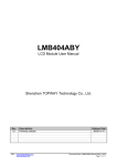
LM1095E
LCD Module User Manual
Shenzhen TOPWAY Technology Co., Ltd.
Rev.
0.1
URL:
Descriptions
New release
www.topwaydisplay.com
www.topwaysz.com
Release Date
2007-02-06
Document Name: LM1095E-Manual-Rev0.1.doc
Page: 1 of 11
TOPWAY
LCD Module User Manual
LM1095E
Table of Content
1.
1.1
1.2
1.3
1.4
Basic Specifications................................................................................................................ 3
Display Specifications............................................................................................................................ 3
Mechanical Specifications ..................................................................................................................... 3
Block Diagram ....................................................................................................................................... 3
Terminal Functions ................................................................................................................................ 4
2.
Absolute Maximum Ratings.................................................................................................... 5
3.
Electrical Characteristics........................................................................................................ 5
3.1
3.2
3.3
3.4
4.
4.1
4.2
4.3
4.4
4.5
4.6
5.
URL:
DC Characteristics................................................................................................................................. 5
LED Backlight Circuit Characteristics .................................................................................................... 5
AC Characteristics ................................................................................................................................. 6
Reset Timing.......................................................................................................................................... 7
Function Specifications .......................................................................................................... 8
Adjusting the Display Contrast .............................................................................................................. 8
Resetting the LCD module..................................................................................................................... 8
Jumper Functions .................................................................................................................................. 8
Display Pixel Map .................................................................................................................................. 8
Command Summary.............................................................................................................................. 9
Initialization Setting Example............................................................................................................... 10
Design and Handling Precaution ......................................................................................... 11
www.topwaydisplay.com
www.topwaysz.com
Document Name: LM1095E-Manual-Rev0.1.doc
Page: 2 of 11
TOPWAY
LCD Module User Manual
LM1095E
1. Basic Specifications
1.1
Display Specifications
1) LCD Display Mode
: FSTN, Positive, Transflective
2) Display Color
: Display Data = “1” : Dark Gray (*1)
: Display Data = “0” : Light Gray (*2)
3) Viewing Angle
:6H
4) Driving Method
: 1/128 duty, 1/12 bias
5) Backlight
: White LED backlight
Note:
*1. Color tone may slightly change by Temperature and Driving Condition.
*2. The Color is defined as the inactive / background color
1.2
Mechanical Specifications
1) Outline Dimension
: 93.4 x 72.7 x 10.1MAX (exclude FFC terminal)
see attached Outline Drawing for details
1.3
Block Diagram
BLA
/WR, /RD, /CS, A0, /RES
DB0~DB7
/WAIT
URL:
www.topwaydisplay.com
www.topwaysz.com
COMMON
Driver
VSS
VOUT, V0, VDD
LED Backlight Circuit
LCD Panel
192 x 128 pixels
Power
Circuit
SEGMENT
Driver
S1D13700 or equivalent
Document Name: LM1095E-Manual-Rev0.1.doc
Page: 3 of 11
TOPWAY
LCD Module User Manual
1.4 Terminal Functions
Pin
Pin
I/O
No.
Name
1
VOUT
Power
2
V0
Input
3
VDD
Power
4
VSS
Power
5
/WAIT
Output
6
NC
7
/CS
Input
LM1095E
Descriptions
Power Booster Output for V0
LCD Contrast Reference Input
Positive Power Supply
0V Power Supply, GND
Wait signal (*1)
No connection, leave open
Chip Select Signal
/CS=LOW: Data IO is enabled
8
A0
Input
Data Type Select
A0=H: command write, display data or cursor add read
A0=L: status flag read, display data or parameter write
9
10
11
:
18
19
/WR(R/W)
/RD(E)
DB0
:
DB7
/RES
Input
Input
I/O
Write enable input, active LOW
Read enable input, active LOW
8-bit bi-directional data bus
Input
Reset Signal:
/RES = L, Reset the LCD Module
/RES = H, Normal Running
20
BLA
Power
Positive Power Supply for LED backlight
note:
*1.
URL:
If there is no read write activity, /WAIT will be in HZ state.
www.topwaydisplay.com
www.topwaysz.com
Document Name: LM1095E-Manual-Rev0.1.doc
Page: 4 of 11
TOPWAY
LCD Module User Manual
LM1095E
2. Absolute Maximum Ratings
Items
Supply Voltage
Input Voltage
Operating Temperature
Storage Temperature
Symbol
VDD
VIN
TOP
TST
Min.
0
VSS-0.3
-20
-30
Max.
+7.0
VDD+0.3
+70
+80
Unit
V
V
°C
°C
Condition
VSS = 0V
VSS = 0V
No Condensation
No Condensation
Cautions:
Any Stresses exceeding the Absolute Maximum Ratings may cause substantial damage to the device. Functional operation of this
device at other conditions beyond those listed in the specification is not implied and prolonged exposure to extreme conditions may
affect device reliability.
3. Electrical Characteristics
3.1
DC Characteristics
VSS=0V, VDD=5.0V, TOP=25°C
Unit Applicable Pin
VDD
V
V0
V
Items
Operating Voltage
LCD Contrast Ref.
Symbol
VDD
VV0
MIN.
4.5
-
TYP.
5.0
16.7
MAX.
5.5
-
Input High Voltage
VIN
0.8xVDD
-
VDD
V
Input Low Voltage
VIN
VSS
-
0.15xVDD
V
Operating Current
IDD
-
15.0
43.0
mA
3.2
DB0~DB7, /WR, /RD, /CS,
A0, /RES
DB0~DB7, /WR, /RD, /CS,
A0, /RES
VDD
LED Backlight Circuit Characteristics
Items
Forward Voltage
Forward Current
Symbol
VfBLA
IfBLA
MIN.
-
TYP.
5.0
85
MAX.
110
VSS=0V, IfBLA=85mA, TOP =25°C
Unit
Applicable Pin
BLA
V
BLA
mA
Cautions:
Exceeding the recommended driving current could cause substantial damage to the backlight and shorten its lifetime.
BLA
VSS
URL:
www.topwaydisplay.com
www.topwaysz.com
No. of LED = 5pcs
Document Name: LM1095E-Manual-Rev0.1.doc
Page: 5 of 11
TOPWAY
3.3
LCD Module User Manual
LM1095E
AC Characteristics
3.3.1
8080 Mode
Item
/CS setup time
A0 setup time
/WR, /RD falling edge to /WAIT driven low
D[7:0] setup time to /WR rising edge (write cycle)
/RD falling edge to D[7:0] driven (read cycle)
/CS hold time
A0 hold time
/RD, /WR rising edge to WAIT# high impedance
D[7:0] hold time from /WR rising edge (write cycle)
D[7:0] hold time from /CS rising edge (read cycle)
/WAIT rising edge to valid Data
/RD, /WR pulse inactive time
/WAIT pulse active time
Symbol
t1
t2
t3
t4
t5
t6
t7
t8
t9
t10
t11
t12
t13
MIN.
7
7
1.6
(*2)
4
9
9
1.6
6.5
2.4
(*4)
-
VSS=0V, VDD=5.0V, TOP=25°C
TYP.
MAX.
Unit
ns
ns
20
ns
ns
ns
ns
ns
13
ns
ns
18
ns
(*3)
ns
ns
(*5)
ns
Note:
*1. Ts
*2. t4min
*3. t11max
*4. t12min
= System clock period
= 2Ts + 5
= 1Ts + 7 (for 5.0V)
= 1Ts (for a read cycle followed by a read or write cycle)
= 2Ts + 2 (for a write cycle followed by a write cycle)
= 5Ts + 2 (for a write cycle followed by a read cycle)
*5. t13max = 4Ts + 2
*6. Input signal rise/fall time should be less than 4.5ns
*7. for details, please see the S1D13700 data sheet
Bus Timing Diagram
URL:
www.topwaydisplay.com
www.topwaysz.com
Document Name: LM1095E-Manual-Rev0.1.doc
Page: 6 of 11
TOPWAY
3.4
LCD Module User Manual
LM1095E
Reset Timing
Item
Oscillator Stable Delay (*1)
Reset Pulse Duration (*2)
Symbol
t1
t2
MIN.
4.0
1.3
VSS=0V, VDD=5.0V, TOP=25°C
TYP.
MAX.
Unit
ms
ms
note:
*1. A delay is required after exiting power save mode. Writing the SYSTEM SET command will exit power
save mode and start the internal oscillator.
*2. It requires a reset pulse after power-on in order to re-initialize its internal state.
Reset Timing Diagram
URL:
www.topwaydisplay.com
www.topwaysz.com
Document Name: LM1095E-Manual-Rev0.1.doc
Page: 7 of 11
TOPWAY
LCD Module User Manual
LM1095E
4. Function Specifications
LCD module
4.1 Adjusting the Display Contrast
A Variable-Resistor must be connected to the
LCD module for providing a reference to V0.
Adjusting the VR will result the change of LCD
display contrast.
The recommended value of VR is 25k to 50k
VOUT
V0
VSS
4.2 Resetting the LCD module
The LCD module should be initialized by hardware reset, using /RES terminal.
Jumper Functions
4.3
Interfacing Setting
Jumper
Function Description
JP5
JP8
Open
Close CNF3=L, 8080 mode selected <default>
Close
Open CNF3=H, 6800 mode selected
4.3.1
Clock Divider Setting
Jumper
JP3
JP4
JP6
JP7
Open
Open Close Close
Close
Open Open Close
Open
Close Close Open
4.3.2
4.4
Function Description
1/4 clock divider
1/8 clock divider <default>
1/16 clock divider
Display Pixel Map
1,1
(D7)
2,1
(D6)
3,1
(D5)
4,1
(D4)
5,1
(D3)
---
---
188,1
(D4)
189,1
(D3)
190,1
(D2)
191,1
(D1)
192,1
(D0)
1,2
(D7)
2,2
(D6)
3,2
(D5)
4,2
(D4)
5,2
(D3)
---
---
188,2
(D4)
189,2
(D3)
190,2
(D2)
191,2
(D1)
192,2
(D0)
1,3
(D7)
2,3
(D6)
3,3
(D5)
4,3
(D4)
5,3
(D3)
---
---
188,3
(D4)
189,3
(D3)
190,3
(D2)
191,3
(D1)
192,3
(D0)
:
:
:
:
:
:
:
:
:
:
:
:
:
:
:
:
:
:
:
:
:
:
:
:
:
:
:
:
:
:
:
:
:
:
:
:
1,126
(D7)
2,126
(D6)
3,126
(D5)
4,126
(D4)
5,126
(D3)
---
---
188,126
(D4)
189,126
(D3)
190,126
(D2)
191,126
(D1)
192,126
(D0)
1,127
(D7)
2,127
(D6)
3,127
(D5)
4,127
(D4)
5,127
(D3)
---
---
188,127
(D4)
189,127
(D3)
190,127
(D2)
191,127
(D1)
192,127
(D0)
1,128
(D7)
2,128
(D6)
3,128
(D5)
4,128
(D4)
5,128
(D3)
---
---
188,128
(D4)
189,128
(D3)
190,128
(D2)
191,128
(D1)
192,128
(D0)
Pixel mapping (Top View)
Note:
*1.
*2.
URL:
Based on the top view of the LCD module,
the 1, 1 (x, y) pixel is the upper-left pixel;
the 192, 128 (x, y) pixel is the lower-right pixel.
For the details of memory mapping please refer to S1D13700 datasheet.
www.topwaydisplay.com
www.topwaysz.com
Document Name: LM1095E-Manual-Rev0.1.doc
Page: 8 of 11
TOPWAY
LM1095E
1
0
0
P2
0
1
0
MOD
0
0
0
P3
P4
P5
P6
P7
P8
-
0
0
0
0
0
0
1
1
1
1
1
1
1
1
0
0
0
0
0
0
0
0
0
0
0
0
1
0
1
0
0
1
-
1
1
0
0
1
0
1
1
0
P1
P1
P2
P3
P4
P5
P6
P7
P8
P9
0
1
0
0
0
0
0
0
0
0
0
1
1
1
1
1
1
1
1
1
1
1
0
0
0
0
0
0
0
0
0
0
0
FP5
FP4
FP3
FP2
FP1
0
1
0
0
0
A7
A6
A5
A4
A15
A14
A13
L7
L6
A7
P10
0
1
P1
P2
1
0
0
CSRDIR
-
OVLAY
POWER
SAVE
DISP
ON/OFF
SCROLL
CSRFORM
CGRAM
ADR
HDOT SCR
CSRW
CSRR
GRAY
SCALE
MWRITE
MREAD
IV
D0
D5
0
0
D1
D6
0
0
D2
D7
1
1
D3
/WR
1
0
ParaCommand meter
SYSTEM
SET
P1
D4
/RD
Command Summary
A0
4.5
LCD Module User Manual
0
1
0
0
0
0
W/S
M2
0
M0
HEX Descriptions
40 Init device and display (with 8 parameters)
**
M0=0: internal CG ROM
M0=1: internal CG RAM
M2=0: 8-pixel char height
M2=1: 16-pixel char height
W/S=0: single panel drive
W/S=1: dual panel drive
IV=0: Screen top-line correction
IV=1: No screen top-line correction
FX=Horizontal Char Size in pixels – 1 (define the horizontal char size)
MOD=0: 16-line AC drive
MOD=1: two frame AC drive
FX
**
FY
1
**
**
**
**
**
**
53
0
D
58 / 59
FP0
FC1
FC0
1
0
0
A3
A2
A1
A0
A12
A11
A10
A9
A8
L5
L4
L3
L2
L1
L0
A6
A5
A4
A3
A2
A1
A0
A15
A14
A13
A12
A11
A10
A9
A8
L7
L6
L5
L4
L3
L2
L1
L0
A7
A6
A5
A4
A3
A2
A1
A0
A15
A14
A13
A12
A11
A10
A9
A8
A7
A6
A5
A4
A3
A2
A1
A0
**
44
**
**
**
**
**
**
**
**
**
0
A15
A14
A13
A12
A11
A10
A9
A8
**
1
1
1
0
0
0
0
0
0
0
0
1
0
0
1
1
0
1
X3
X2
X1
X0
CM
1
0
0
Y3
Y2
Y1
Y0
5D
**
**
1
1
0
0
1
0
0
1
1
CD1
CD0
4C~4F
P1
P1
P2
P1
P1
P2
P1
P2
P1
1
0
1
0
0
1
0
1
0
0
1
1
1
1
0
1
1
1
1
1
1
1
1
1
1
1
0
0
1
1
0
0
0
0
0
0
0
0
0
0
0
1
1
0
0
0
0
0
1
0
1
0
0
0
1
0
1
1
1
1
1
0
0
A7
A6
A5
A4
A3
A2
A1
A0
A15
A14
A13
A12
A11
A10
A9
A8
0
0
0
1
0
1
0
0
0
1
0
0
1
0
0
0
1
0
D2
D1
D0
1
1
0
A7
A6
A5
A4
A3
A2
A1
A0
A15
A14
A13
A12
A11
A10
A9
A8
0
1
0
0
0
1
1
1
A7
A6
A5
A4
A3
A2
A1
A0
A15
A14
A13
A12
A11
A10
A9
A8
0
0
1
0
1
0
0
0
0
0
0
0
0
0
5B
**
5C
**
**
5A
**
46
**
**
47
**
**
60
**
Set display overlay format (with 1 parameters)
OV
P1
:
Pn
P1
:
Pn
1
0
:
0
1
1
:
1
1
1
:
1
1
0
:
0
0
0
:
0
0
1
:
1
0
1
0
0
0
0
42
**
**
**
43
**
**
**
Write to display memory (with n parameters)
C/R
TC/R
L/F
APL
APH
1
DM2 DM1 MX1
MX0
BPP1 BPP2
1
0
Memory Data
:
Memory Data
0
1
0
0
0
0
Memory Data
:
Memory Data
1
1
FY=Vertical Char Size in pixels – 1 (define the vertical char size)
C/R: Character Bytes per Row
TC/R: Total Char Bytes per Row (including horizontal blanking)
L/F: Lines per Frame
APL: Horizontal address range of the virtual screen (low byte)
APH: Horizontal address range of the virtual screen (high byte)
Power Save Mode Enable
Enable and disable display and display flashing (with 1 parameter)
D=0: Display OFF
D=1: Display ON
Each pair of bit in FP sets the attributes of one screen block
Set display start address and display regions (with 8 or 10 parameters)
Screen Block 1 Start Address (SAD1) LSB
Screen Block 1 Start Address (SAD1) MSB
Screen Block 1 Size Register (SL1)
Screen Block 2 Start Address (SAD2) LSB
Screen Block 2 Start Address (SAD2) MSB
Screen Block 2 Size Register (SL2)
Screen Block 3 Start Address (SAD3) LSB
Screen Block 3 Start Address (SAD3) MSB
Screen Block 4 Start Address (SAD4) LSB
(for dual panel drive and two layer config are select)
Screen Block 4 Start Address (SAD4) MSB
(for dual panel drive and two layer config are select)
Set cursor type (with 2 parameters)
CRX
CRY
CM=0: underscore cursor; CM=1: block cursor
Set Direction of Cursor movement
CD=00: Right; CD=01: Left,; CD=10: Up; CD=11: Down
Set Start address of char generator RAM (with 2 parameters)
SAGL
SAGH
Set horizontal scroll position (with 1 parameters)
Set cursor address (with 2 parameters)
CSRL
CSRH
Read Cursor Address (with 2 parameters)
CSRL
CSRH
select the gray scale depth (in bits-per-pixel)
BPP=00: 1 bits-per-pixel; BPP=01: 2 bits-per-pixel;
BPP=10: 4 bits-per-pixel; BPP=01: reserved
Display memory data
Read from display memory (with n parameters)
Display memory data
Note:
For details please refer to S1D13700 datasheet.
URL:
www.topwaydisplay.com
www.topwaysz.com
Document Name: LM1095E-Manual-Rev0.1.doc
Page: 9 of 11
TOPWAY
LCD Module User Manual
LM1095E
A0
/RD
/WR
4.6 Initialization Setting Example
The following setting should be issue to LCD module after hardware reset.
(example could be adjusted if necessary.)
1
0
1
1
0
0
Value
(binary)
0100 0000
0011 0000
P2
0
1
0
1000 0111
87
P3
P4
P5
P6
P7
P8
P1
P1
P2
P3
P4
P5
P6
P7
P8
P1
P2
P1
0
0
0
0
0
0
1
0
1
0
0
0
0
0
0
0
0
1
0
0
1
1
0
1
1
1
1
1
1
1
1
1
1
1
1
1
1
1
1
1
1
1
1
1
1
1
0
0
0
0
0
0
0
0
0
0
0
0
0
0
0
0
0
0
0
0
0
0
0
0000 0111
0001 0111
0100 1001
0111 1111
0001 1000
0000 0000
0101 1001
0000 0100
0100 0100
0000 0000
0000 0000
0111 1111
0000 0000
0000 1100
0111 1111
0000 0000
0001 1000
0101 1101
0000 0111
0001 0111
0100 1100
0101 1011
0000 0101
07
17
47
7F
18
00
59
04
44
00
00
7F
00
0C
7F
00
18
5D
07
17
4C
5B
05
FY=7: the vertical char size=7+1=8
P1
P1
P1
P2
P1
:
Pn
1
0
1
0
1
0
0
1
0
:
0
1
1
1
1
1
1
1
1
1
:
1
0
0
0
0
0
0
0
0
0
:
0
0101 1010
0000 0000
0110 0000
0000 0000
0100 0110
0000 0000
0000 0000
0100 0010
5A
00
60
00
46
00
00
42
**
**
**
Set horizontal scroll position (with 1 parameters)
Command Parameter
SYSTEM
SET
P1
DISP
ON/OFF
SCROLL
CSRFORM
CSRDIR
OVLAY
HDOT SCR
GRAY
SCALE
CSRW
MWRITE
Memory Data
:
Memory Data
HEX
40
30
Descriptions
Init device and display (with 8 parameters)
M0=0: internal CG ROM
M2=0: 8-pixel char height
W/S=0: single panel drive
IV=1: No screen top-line correction
FX=7: the horizontal char size=7+1=8
WF=1: two frame AC drive
C/R: Character Bytes per Row
TC/R: Total Char Bytes per Row (including horizontal blanking)
L/F: Lines per Frame
APL: Horizontal address range of the virtual screen (low byte)
APH: Horizontal address range of the virtual screen (high byte)
Display ON
sets the attributes of screen block (SAD1 on, cursor off)
Set cursor type (with 10 parameters)
SAD 1L
SAD 1H
SL1
SAD 2L
SAD 2H
SL2
SAD3L
SAD3H
Set cursor type (with 2 parameters)
CRX
CRY
Set Direction of Cursor movement
Set display overlay format (with 1 parameters)
OV=0: two layer in used; DM1=0: layer 3 as text mode;
DM0=1: layer 1 as graphic mode; MX=01: layer1 XOR Layer 2
no scroll
sel select the gray scale depth (in bits-per-pixel)
BPP=00: 1 bits-per-pixel
Set cursor address (with 2 parameters)
CSRL
CSRH
Write to display memory (with n parameters)
Display memory data
Note:
For details please refer to S1D13700 datasheet.
URL:
www.topwaydisplay.com
www.topwaysz.com
Document Name: LM1095E-Manual-Rev0.1.doc
Page: 10 of 11
TOPWAY
LCD Module User Manual
LM1095E
5. Design and Handling Precaution
1.
2.
3.
4.
5.
6.
7.
8.
9.
10.
11.
12.
13.
14.
15.
16.
17.
18.
URL:
The LCD panel is made by glass. Any mechanical shock (eg. dropping form high place)
will damage the LCD module.
Do not add excessive force on the surface of the display, which may cause the Display
color change abnormally.
The polarizer on the LCD is easily get scratched. If possible, do not remove the LCD
protective film until the last step of installation.
Never attempt to disassemble or rework the LCD module.
Only Clean the LCD with Isopropyl Alcohol or Ethyl Alcohol. Other solvents (eg. water)
may damage the LCD.
When mounting the LCD module, make sure that it is free form twisting, warping and
distortion.
Ensure to provide enough space (with cushion) between case and LCD panel to
prevent external force adding on it, or it may cause damage to the LCD or degrade the
display result.
Only hold the LCD module by its side. Never hold LCD module by add force on the heat
seal or TAB.
Never add force to component of the LCD module. It may cause invisible damage or
degrade of the reliability.
LCD module could be easily damaged by static electricity. Be careful to maintain an
optimum anti-static work environment to protect the LCD module.
When peeling off the protective film from LCD, static charge may cause abnormal
display pattern. It is normal and will resume to normal in a short while.
Take care and prevent get hurt by the LCD panel sharp edge.
Never operate the LCD module exceed the absolute maximum ratings.
Keep the signal line as short as possible to prevent noisy signal applying to LCD
module.
Never apply signal to the LCD module without power supply.
IC chip (eg. TAB or COG) is sensitive to the light. Strong lighting environment could
possibly cause malfunction. Light sealing structure casing is recommend.
LCD module reliability may be reduced by temperature shock.
When storing the LCD module, avoid exposure to the direct sunlight, high humidity, high
temperature or low temperature. They may damage or degrade the LCD module
www.topwaydisplay.com
www.topwaysz.com
Document Name: LM1095E-Manual-Rev0.1.doc
Page: 11 of 11