1
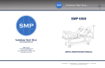
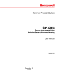
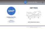
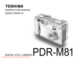
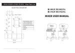
Solutions Start Here... SMP 7000 ELITE Solutions Start Here www.smpcanada.com SMP Canada 10 Sims Crescent, Richmond Hill Ontario, L4B-1K9 Canada Tel: (905) 764-7767 Fax: 1-866-627-9798 [email protected] USER & MAINTENANCE MANUAL www.smpcanada.com | [email protected] | Tel: 1.905.764.7SMP (1.905.764.7767) | Fax: 1.866.627.9798 10 Sims Crescent, Richmond Hill Ontario, L4B 1K9, Canada USER MANUAL ICU BED SMP 7000 ELITE APPENDIX C SMP-7000 ELITE ICU Bed – User & maintenance Manual Removable headboard X-ray Translucent surface Side rail controls (patient) Removable footboard IV pole with 4 hooks Manual CPR Hand controller Central locking system P1 Side rail controls (nurse) USER MANUAL ICU BED SMP 7000 ELITE General Remarks We congratulate you on your choice of a SMP-7000 ELITE ICU bed and would like to thank you for your confidence in our company and its products. You have purchased a SMP-7000 ELITE ICU bed, developed and manufactured in accordance with the current state of technical knowledge. SMP Canada’s ICU beds fully meet all safety and operational requirements. They are tested in accordance with international standard and carry the CE seal. This confirms that they fulfill the safety requirements relating to medical products. This user manual is intended to give you and your staff practical information and tips on the safe and correct use of the SMP-7000 ELITE ICU bed. When putting the bed into service for the first time, or wanting to learn about its operation and maintenance, one must read and strictly obey this user manual. To avoid faulty handling and to ensure trouble-free operation of the bed, this documentation must be available to caregivers and/or patients at all times. Secondary Medical Products Canada Inc. SMP Canada 10 Sims Crescent Richmond Hill, Ontario, L4B 1K9 Canada Tel.: ++1 905-764-7767 Fax: ++1 866-627-9798 E-Mail: [email protected] Website: www.smpcanada.com Form 308 Rev.05/13 P2 USER MANUAL ICU BED SMP 7000 ELITE Table of Contents APPENDIX C ................................................................................................................................................................... 1 General Remarks........................................................................................................................................................... 2 1. Safety Instructions ................................................................................................................................................ 4 2. Bed Installation ..................................................................................................................................................... 4 3. Bed Usage ............................................................................................................................................................. 5 3.1 Hand Controller. ........................................................................................................................................... 5 3.2 Side rail controls ........................................................................................................................................... 6 3.3 Nurse Control Panel (Optional)…………………………………………………………………………………………………………..…..6 3.4 Weight Scale ................................................................................................................................................. 7 3.5 Manual Controls ........................................................................................................................................... 7 3.5.1 Legrest adjustment mechanism............................................................................................................ 7 3.5.2 Side rails ................................................................................................................................................ 8 3.5.3 Manual CPR handle ............................................................................................................................... 8 3.5.4 Central locking system .......................................................................................................................... 8 3.6 P3 Head/Foot Boards ......................................................................................................................................... 8 4. Bed Cleaning ......................................................................................................................................................... 8 5. Storage .................................................................................................................................................................. 9 6. Troubleshooting.................................................................................................................................................... 9 7. Symbols ................................................................................................................................................................. 9 8. Maintenance Inspection Schedule ..................................................................................................................... 10 Form 308 Rev.05/13 USER MANUAL ICU BED SMP 7000 ELITE 1. Safety Instructions Read the statements with detail and use this product in accordance with these statements. If necessary, place a copy of these instructions near the product. If you notice the product is not working, do not use it and contact SMP’s technical service right away/ Inform the patient and the other users about the functions of the product. Pay attention the situation of the patient and around before operating the patient bed. The safety weight capacity should not be exceeded. If there is an obligatory situation to exceed this limit, the surface which the patient lies on should be adjusted to lowest position and the functions of the bed should not be used. When the patient is on the bed, a second person should not sit on the bed. Before cleaning the bed or changing any part of the bed, always pull the power cable out the plug. The patient and the attendant are always in danger in the following situations: o In the course of taking the bed away from one place to another on crinkled or grungy surface o In the course of exceeding the safe working weight o In the course of placing the moving parts carelessly o In the course of being damaged of the power cable Only the approved brands’ parts should be used. When the replacement parts which are provided from the other suppliers are used, the bed manufacturer company will not accept responsibility for any damage, loss or injury. 2. Bed Installation During the installation of the bed, please obey the following rules: Open the package of the bed completely and carefully Check the bed for the possible damages during the carriage Check the accessories and the main parts of the bed for any deficiency carefully, in case of any deficiency, contact the service department Before taking action about the bed, read the user’s manual carefully *WARNING* DO NOT PUT ANYTHING ON THE BOTTOM FRAME COVER Form 308 Rev.05/13 P4 USER MANUAL ICU BED SMP 7000 ELITE 3. Bed Usage 3.1 Hand Controller The controller is connected with a flexible cable so the patient and the attendant can use the controller in every position. FUNCTIONS: 1. Backrest incline 2. Backrest decline 3. Legrest incline 4. Legrest decline 5. Fowler position increase 6. Fowler position decrease 7. Height increase 8. Height decrease 9. Trendelenburg (12°) 10.Reverse Trendelenburg (12°) *WARNING* MAKE SURE THERE IS NOTHING AND NOBODY, ESPECIALLY CHILDREN, UNDER AND NEAR THE BED WHEN OPERATING THE FUNCTIONS OF THE BED. P5 Form 308 Rev.05/13 USER MANUAL ICU BED SMP 7000 ELITE 3.2 Side rail controls 1. 2. 3. 4. 5. 6. 7. 8. 3.3 Fowler position increase Fowler position decrease Legrest incline Legrest decline Height increase Height decrease Backrest incline Backrest decline Nurse Control Panel FUNCTIONS: 1 2 3 4 5 6 7 8 9 Electronic CPR Backrest incline Legrest incline Fowler position increase Height increase Trendelenburg Shock position Lock Button Lock Button 12 13 14 15 16 17 18 19 20 Backrest lock Legrest decline Legrest lock Fowler position decrease Fowlet position lock Height decrease Height adjustment lock Form 308 Rev.05/13 Reverse Trendelenburg Trendelenburhg Lock P6 USER MANUAL ICU BED SMP 7000 ELITE 3.4 1 2 3 4 5 6 7 8 9 1 210 3.4 3 4 5 6 7 8 9 10 Weight Scale Accuracy Scaling Display screen Auto compensation Reset Unit change Enabling Enabling Out of bed volume adjustment Accuracy Scaling Out of bed alarm Weight Scale Display screen Auto compensation Reset Unit change Enabling Enabling Out of bed volume adjustment Out of bed alarm 3.5 Manual Controls Some of the features of the bed do not require electrical functionalities hence they can be adjusted manually. 3.5 Manual Controls Some of the features of the bed do not require electrical functionalities hence they can be adjusted manually. 3.5.1 Legrest adjustment mechanism Legrest movement is done by the help of a graded mechanism. Upholding the legrest is enough to uphold the graded mechanism. To lower again, uphold the legrest and then let it down. The legrest will come to straight position 3.5.1 Legrest adjustment mechanism Legrest movement is done by the help of a graded mechanism. Upholding the legrest is enough to uphold the graded mechanism. To lower again, uphold the legrest and then let it down. The legrest will come to straight position P7 Form 308 Rev.05/13 Form 308 Rev. 5/13 USER MANUAL ICU BED SMP 7000 ELITE 3.5.2 Side rails There are four side rails on the bed for the safety of the patients. The side rails prevents the patient from falling out of bed and to avoid from external factors. The safe carriage capacity of each side rail is 75 kg. Opening/Closing the side rail: To lower the side rail, pull the red latch to release the side rail and let it fold down. To raise the side rail, pull the lowered side rail upward. In both movements, the side rail locking mechanism becomes active automatically. 3.5.3 Manual CPR handle To lower the backrest manual in an emergency situation, pull the handle located at the back of the backrest downward. Use this application to lower the patient’s back in an emergency situation. 3.5.4 Central locking system To activate the central lock, simply push down on brake pedal located at the end of the bed. Pushing the pedal down will lock all the wheels and prevent the bed from moving. To release the central brake use your foot to lift the pedal. Releasing the central brake will allow the bed to move freely. 3.6 Head/Foot Boards The head and foot boards are designed to protect the patient from the environmental effects and increase the comfort of the patient. These boards are removable and can be installed easily. To remove the head/foot baords, simply pull on them by holding the top part and the boards will pop out of their holders. To install the head/foot boards, align the holes located at the bottom of the boards with the holders on the bed frame and simply push down to fix them in place. 4. Bed Cleaning All SMP ICU bed models can be cleaned easily. The beds can be cleaned with a damp-dry duster. Make sure to discharge the patient out of the bed before commencing cleaning of the bed. *WARNING* NEVER USE ACID, DISSOLVENT, DETERGENT, PHOSPHATE OR ANY CHEMICAL INLCUDING PHOSPHATE OR ANY OTHER CORRIVE AGENTS. 5. Storage Formfollowing 308 Rev.05/13instructions: For the long term storage of the bed, obey the Reset all of the adjustments of the bed P8 All SMP ICU bed models can be cleaned easily. The beds can be cleaned with a damp-dry duster. Make sure to discharge the patient out of the bed before commencing cleaning of the bed. USER MANUAL *WARNING* NEVER USE ACID, DISSOLVENT, DETERGENT, PHOSPHATE OR ANY CHEMICAL INLCUDING OR ANY OTHER CORRIVE AGENTS. ICU BEDPHOSPHATE SMP 7000 ELITE 5. Storage For the long term storage of the bed, obey the following instructions: Reset all of the adjustments of the bed Be sure that all the wheels of the bed are on a level surface Do not place any other bed or a heavy subject on the bed 6. Troubleshooting PROBLEM 6. Troubleshooting 6. Troubleshooting Form 308 Rev. 5/13 REASON The bed is not responding to any 1. The power inlet is not plugged in. commands. 2. The electric cable is not working. PROBLEM PROBLEM REASON REASON 3. The control box is SOLUTION SOLUTION not working. 6. Troubleshooting PROBLEM The bed is not responding to any commands. REASON 1. The power in 2. The electric c 3. The control b The system is working but the SOLUTION motor is not working. There is a “click”1.sound coming from the Plug the power inlet in. control 2.box.Change the electric cable. 1. 2. Send the control box to3. The bed is not Theresponding bed is not to responding any to any 1. The power 1. inlet The power is not plugged inlet is not in. plugged in.1. Plug the1.power Pluginlet the power in. inlet in. repair. commands. commands. 2. The electric 2. The cable electric is not cable working. is not working.2. Change2. the Change electric cable. the electric cable. The system is working but3.theThe control The socket connection 1. control Check the described socket 1. 3. The box1.control is not working. box is notwhich working.has3. a Send the 3. Send control box tois working box to Thethe system but the motor is not working. There is a with the control box of the motor isrepair. if it is connected or not. repair. motor is not working. No “click” 2. “click” sound coming not aconnected. 2.described The motor needs to change, sound is coming from the control The system is The working system but is working the butfrom the 1.theThe socket 1. The which socket has which connection has a connection 1. Check the 1. described Check thesocket socket box. motor is notmotor working. is not There working. is a There is a with the control with box control of motor the motor boxisofbroken. isthe motor isif it is connected if it is or connected not. call orthe not.service. control box. 2. the The “click” sound“click” coming sound fromcoming the from the not connected. not3.connected. 2. The motor 2. needs The motor to change, change, box needs to The control box is broken. 3.needs Thetocontrol control box.control box. 2. The motor 2. isThe broken. motor is broken. call the service. call The the service. batterychange, is out ofcall charge. 1. the No service 3. The control 3. The box control is broken. box is broken. 3. The control 3. The box “click“ control needs sound tobox needs to is present. department. change, call change, the service call the service 2. The system is working but the 1. The control box is broken.department.department. 1. The control box needs to 1. While the system is working, but motor isbut not working. Thebox actuator is broken.1. The control change, call the service. The system is The working system is working the but No the “click” 1. The control 1. The box2.control is broken. is broken. 1. The boxthe control needs tobox needs motors are not to moving 2. The actuator needs to sound is coming from the control motor is notmotor working. is not Noworking. “click” No “click” 2. The actuator 2. The is broken. actuator is broken. change, call change, the properly. service. call the service. change, box.from sound is coming sound is coming the control from the control 2. The actuator 2. The needs actuator to needs to call the service box. box. change, call change, the service call thedepartment. service department. department. The battery is out of charge. No 1. The battery is completely out of Charge the battery. 7.1. Symbols The battery The is“click“ out battery of charge. is outis No ofpresent. charge. No1. The battery 1. The is battery completely is completely out of out1. ofCharge 1. the battery. Charge the sound charge. 2.battery. Change the battery. “click“ sound“click“ is present. sound is present. charge. charge. 2. Change2. the Change battery.the battery. 2.battery The isbattery is broken. 2. The battery 2. The is broken. broken. While the system is working, 1.battery The isbattery out of 1. Charge While the system While isthe working, system but is working, but 1. but The battery 1. The is completely out completely of is completely out of 1. Charge the battery, Charge the if1. it battery, if itthe battery, if it the motors moving charge. not help, call the the motors are the not motors moving areare notnot moving charge. charge. does not help, does callnot thehelp, does call the B Type properly. service department. properly. properly. service department. service department. 3. 7. Symbols 7.7.Symbols Symbols B Type B Type Equipotential Equipotential Look at the user’s Look atguide. the user’s guide. Weight =Safety 175 KgWorking Safety Working Weight = 175 Kg Safety Working Weight = 175 Kg Look at the user’s guide. Bonding Bonding Equipotential = 175 Kg The control b The actuator The battery charge. The battery is The battery is charge. Equipotential B Type P9 The socket w with the cont not connecte The motor is The control b Bonding Form 308 Rev.05/13 Safety Working Weight USER MANUAL ICU BED SMP 7000 ELITE 8. Maintenance Inspection Schedule TECHNICIAN NAME SIGNATURE DATE EXPLANATION Form 308 Rev.05/13 P 10