1
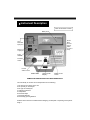
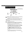
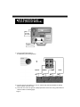
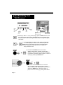
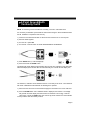
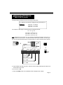
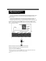
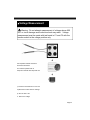
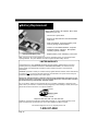
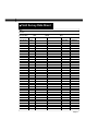
AMPROBE ®
GP-1 EARTH TESTER
GROUND PROBE ™
User’s Manual
Amprobe thanks you for purchasing the GP-1. For your safety, please read this
instruction manual in its entirety.
Part No. 947749 revA
7/2000
!
SAFETY PRECAUTIONS & WARNINGS
1.Read this manual in its entirety before proceeding with any testing.
2.This equipment should only be used by trained professionals who
are familiar with electrical hazards.
3. Wear lineman gloves at all times.
4.This unit has been designed and tested for user and instrument
protection up to 600VAC maximum. Any application, or misapplication, of voltages exceeding 600VAC to any part of this unit
may result in instrument circuit damage and/or lethal electrical shock.
5.Never isolate an earth ground electrode until you have confirmed
that there is no voltage present and there is less than 50mA of
current flowing through it.
Page 2
Table of Contents
Instrument Description . . . . . . . . . . . . . . . . . . . . . . . . . . . . . . . . . . . . . . . . . .4
Items Affecting Ground Electrode Resistance . . . . . . . . . . . . . . . . . . . . . . . . .4
Memory Storage Control . . . . . . . . . . . . . . . . . . . . . . . . . . . . . . . . . . . . . . . . .5
Soil Resistivity Test A (Wenner Method) . . . . . . . . . . . . . . . . . . . . . . . . . .6, 7, 8
Two Point Ground/Earth Continuity Test B . . . . . . . . . . . . . . . . . . . . . . . . . . . .9
Electrode Resistance Test C & D . . . . . . . . . . . . . . . . . . . . . . . . .10, 11, 12, 13
Conclusion . . . . . . . . . . . . . . . . . . . . . . . . . . . . . . . . . . . . . . . . . . . . . . . . . .14
Voltage Measurement . . . . . . . . . . . . . . . . . . . . . . . . . . . . . . . . . . . . . . . . . .15
Battery Replacement . . . . . . . . . . . . . . . . . . . . . . . . . . . . . . . . . . . . . . . . . . .16
Field Survey Data Sheet . . . . . . . . . . . . . . . . . . . . . . . . . . . . . . . . . . . . . . . .17
Specifications . . . . . . . . . . . . . . . . . . . . . . . . . . . . . . . . . . . . . . . . . . . . . . . .18
We recommend the user be equipped with the following items to be fully prepared to perform tests:
• LINEMAN’S GLOVES (to be worn at all times).
• A NON-METALLIC, 100 FT. TAPE MEASURE TO CORRECTLY SPACE THE TEST RODS.
• CALCULATOR TO CALCULATE PROPER TEST ROD DISTANCES.
• A 3 LB. HAMMER TO POUND TEST RODS IN HARD SOIL.
• WATER TO TREAT SOIL AROUND TEST RODS (if necessary).
• A CLEAN CLOTH TO CLEAN RODS AND INSTRUMENT AFTER USE.
Page 3
Instrument Description
View of Instrument Controls
Battery Cover
Control
Panel
(see next
page for
details
on control
panel)
Test
lead/cable
input ports
RS-232
output port
Power
ON/OFF
Fuse/Fuse
Holder
Function
selector switch
START button
Liquid Crystal
Display
Battery Cover
Screw
ITEMS AFFECTING GROUND ELECTRODE RESISTANCE
The soil’s ability to conduct current is dependent on the following:
1.The amount of moisture in the soil
2.The quantity of electrolytes
3.The type of electrolytes
4. Adjacent conductors
5. Temperature
6. Electrode depth
7. Electrode diameter
8. Electrode(s) spacing distance
All these factors must be considered when designing an adequate or required ground system.
Page 4
Memory Storage Control
View of Control Panel
METER/
FEET
SELECTOR
button
CLEAR
button
DISTANCE
SELECTOR
button
RECALL
button
SAVE
button
SAVE all test results, excluding voltage, can be saved into memory by pressing the
SAVE button. Each time the SAVE button is pressed, the next consecutive memory
location is displayed and the information is saved to that location.
The RECALL button works in conjunction with the function switch. When the RCL
button is pressed, “mem” and the last memory location will be displayed, followed
by the value, in that location for the test designated by the function switch.
Continuing to press the RCL button will allow the prior measurements and locations
to be displayed.
The CLEAR button has three functions:
1) To clear past memory location (before any other button was pressed or
function changed after saving). After the SAVE button has been pressed, press
the CLEAR button to clear the last memory location. After pressing the CLEAR
button, the cleared memory location will be displayed followed by clr.
2) To CLEAR all memory locations. With the function switch in Test A, B, C,
or D, press the CLEAR button to clear all memory locations. After the CLEAR
button is pressed, clr will flash and “mem” will be displayed. Press the CLEAR
button a second time to conclude memory clearing function. clr will be
displayed for approximately 5 seconds, followed by the three dashes.
3) To clear all memory locations and reset two point calibration. With unit
OFF, press and hold the CLEAR button, then turn the unit ON. ES will be
displayed followed by the three dashes. All memory locations will be cleared.
If a two point (Test B) is to be performed, the unit must be calibrated (nulled)
prior to the test.
To verify that all memory locations have been cleared, switch the function
switch to Test A, then press the RCL button. no mem will be displayed followed
by three dashes. Repeat for Test B, C and D.
Page 5
Soil Resistivity Test:
Test A (Wenner Method)
Test
lead/cable
input jacks
Function
selector switch
1) Turn the FUNCTION switch to
Soil Resistivity (see drawing below).
BLACK
GREEN
C1
P1
RED
P2
BLUE
C2
2) Connect the four test cables to C1, C2, P1 and P2 input jacks (as indicated in drawing
above). Please note color codes.
3) Insert four test rods in the ground, equally spaced from each other, using preset distance
values in tables on following page.
Page 6
Soil Resistivity Test:
Test A Tables (cont’d.)
GP-1 PRESET DISTANCE VALUES IN FEET AND INCHES
Depth of the electrodes
Distance between electrodes
2”
3’
3”
5’
4”
7’
6”
10’
9”
15’
1’
20’
1’6”
30’
2’0”
40’
2’6”
50’
3’0”
60’
3’6”
70’
4’0”
80’
TABLE 1
GP-1 PRESET DISTANCE VALUES - METRIC SYSTEM
Depth of the electrodes
Distance between electrodes
5 cm
1 meter
10 cm
2 meters
15 cm
3 meters
20 cm
4 meters
30 cm
6 meters
40 cm
8 meters
50 cm
10 meters
65 cm
13 meters
80 cm
16 meters
95 cm
19 meters
110 cm
22 meters
125 cm
25 meters
TABLE 2
Page 7
Soil Resistivity Test
Test A (cont’d.)
METER/
FEET
SELECTOR
button
CLEAR
button
DISTANCE
SELECTOR
button
RECALL
button
SAVE
button
Function
selector switch
Control Panel
4) Referring to Table 1 or 2 (on previous page), press the DIST button to scroll
through the preset values until the appropriate distance is displayed. Each
time you perform a test and change the distances, you must go through the
same steps.
5) To change distance in meters, or feet, press the m/ft button.
“m” will be displayed if meters are selected.Then press the
DIST button to scroll through the values until the appropriate
distance is displayed. Repeat process above if distance is
being measured in feet.
6) Push and hold START button until a result is
displayed, then release. Whether you select the
distance in meters or feet, the value will be displayed
in ohmmeters. Record the value on paper, or save it to
memory by pressing the SAVE button.
7) To view the measured resistance from which the
GP-1 calculated resistivity from, turn the selector
switch to TEST D: SOIL RESISTANCE, and push and
release the START button. Record the value on
paper or save it to memory by pressing SAVE button.
Page 8
2-Point Ground/Earth
Continuity Test B
NOTE: To measure ground rod resistance accurately, use test C & D instead of B!
It is necessary to familiarize yourself with the meter before doing the Two Point Measurement
Test B. Calibration is required for this test only.
1) Insert two of the desired test leads or cables into the instrument in C1 and C2 jacks.
2) Short the leads together.
3) Turn the GP-1 power ON.
4) Turn the GP-1 selector switch to Test B: GROUND/EARTH CONTINUITY.
5) Press SAVE button (“k” will be displayed).
6) Push and release the START button
The display will remain blank for approximately five seconds. The resistance of the test leads
will then be displayed for another five seconds and finally, the unit will null and display .00Ω.
The maximum, resistance of test leads that the GP-1 can nullify is five ohms. The instrument
will remain calibrated until the batteries are discharged or replaced.
7) Disconnect the short from the test leads and apply the test leads to the circuit under test.
8) Press the START button until a stabilized result is displayed, then release. The display
will go blank and then display the measurement of resistance in ohms (Rg). Note the
value of Rg or press the SAVE button.The value of Rg will be saved to the next available
memory location. Note the memory location.
Page 9
Electrode or Grid System
Resistance:Test C & D
Warning: The power must be turned OFF, the electrode
must be isolated from the utility ground, building steel, or any
other ground, in order for the GP-1 to correctly measure the
resistance value of an earth ground electrode (Test C).
Before isolating the electrode under test, verify that power is
OFF by:
• Measuring the voltage from the grounding conductor to a
reliable earth ground. Use the voltmeter measurement
feature on the GP-1 (see page 14).
• Measuring the leakage current through the electrode using
an AMPROBE Model DLC-100, or equivalent, Digital
Leakage Current Clamp.
Warning: If more than 50ma of current is flowing through
the electrode, do not isolate the ground electrode until the
source of current is located and turned OFF.
The following instructions outline the typical approach to perform a test using the “fall of
potential” or 62% method.
1) Switch the GP-1 to Test C “Earth Resistance”
2) Noting color codes, connect the four test cables to the input jacks of the instrument.
3) Connect the BLACK (C1) and GREEN (P1) test cables to the isolated electrode under
test.
4) To determine the distances from the electrode in which to drive the tet rods, use the
formula on Page 11.
Page 10
Electrode Resistance:
Test C & D (cont’d.)
Calculate distances between the test rods using formula below:
C2 = (Depth of the electrode or diagonal of the grid system) x 4
FORMULA 1
P2 at 52% = C2
P2 at 62% = C2
P2 at 72% = C2
0.52
* 0.62
*
* 0.72
For example: To test single 10’ deep electrode use following formula:
C2 = 10’ x 4 = 40’
P2 at 52% = 40
P2 at 62% = 40
P2 at 72% = 40
= 21’
* 0.52
0.62 = 25’
*
* 0.72 = 29’
Note: Inside the top cover of the GP-1 you will find a simplified formula which uses 100 ft. or
longer distance for electrode C2. This formula holds in most cases, however, in order to get
the most accurate measurements we recommend that you use the formula from this manual.
BLUE
RED
BLACK
C1
GREEN
P1
P2
at
52%
P2
at
62%
P2
at
72%
C2 at 100%
5) Clip the BLUE test cable (C2) to the 100% test rod and clip the RED (P2) test cable to the
test rod at the 62% mark.
6) Turn the GP-1 ON.
7) Press the START button until a stabilized result is displayed, then release.
Page 11
Electrode Resistance:
Test C & D (cont’d.)
8) The possible results are as follows:
• If the test rods are making good contact with the soil, all connections are correct, and the
actual value is less than 2kΩ, the measured value (RG) will be displayed in ohms (Ω).
Continue to Step 9.
• If the test rods are making good contact with the soil, all connections are correct, and
the actual value is greater than 2kΩ, “o.r.” (over range) will be displayed. Recheck
connections, verify rod to soil continuity and treat if necessary, and/or use longer test rods.
9) Note the value of Rg, or press the SAVE button.The value of Rg at P2@67% will be
saved to the next available memory location. Note the memory location.This is your electrode or grid system resistance.
BLUE
RED
BLACK
GREEN
P2
C2
C1
P1
52%
62%
72%
100%
Perform next steps to assure accuracy of the measurements
10)Remove P2 (RED) from the 62% rod and clip to the 52% rod.
11)Press and release the START button.
12)Note the value of Rg, or press the SAVE button.The value of Rg will be saved in the
next available memory location. Note the memory location.
Page 12
Electrode Resistance:
Test C & D (cont’d.)
BLUE
RED
BLACK
GREEN
C1
P2
C2
P1
52%
62%
72%
100%
13)Remove P2 (RED) from the 52% rod and clip to the 72% rod.
14)Press and release the START button.
15)Note the value of Rg, or press the SAVE button.The value of Rg will be saved to the next
available memory location. Note the memory location.
16)The electrode resistance is equal to point P2 @62%. Points P2 @52% and P2 @72%
are used to confirm the accuracy of the measurements.
The rule of thumb is that in order to perform an accurate measurement, the difference in
resistances between points marked as P(62%) and P(52%) as well as between points
P(72%).
To compute differences use following Formula 2:
Formula 2 (P2 @62%) - (P2 @52%) x 100% < ± 10%
(P2 @62%)
(P2 @72%) - (P2 @62%) x 100% < ± 10%
(P2 @62%)
Page 13
If results on Page 13 are more than 10%, electrodes must be moved farther apar t
(20% - 30% of the distance) and you must retest.
If the change of resistance values measured between the rods is less than 10%, the
resistance value from the point P2 @62% rod is the value of the earth ground resistance.
Explanation:
An auxiliary electrode P2 should be outside of the effective resistance areas of both the
existing ground electrode and the auxiliary electrode C2 as shown on the Drawing 1. In this
case the resistance differences calculated using For mula 2 would be less than 10%. Value P2
@62% is the resistance of the ground rod.
If the effective resistance areas overlap, Drawing 2, the resistance differences calculated
using Formula 2 would be more than 10%. In this case value P2@62% contains error and
cannot be used as a value of the electrode ground resistance.
Conclusion
It is recommended to repeat the test at 180 degrees from the initial test.
The average of both values, measured at the P2/62% mark will give you the average earth
ground resistance. If you cannot test at 180 degrees, then test at 90 degrees. If the two
measurements greatly vary from each other, then it may be wise to perform a third and,
possibly, a fourth test.
As an additional test, continue to move electrodes in cross effect (see drawing at right).
This is a good way to check the accuracy of the tests.
Existing
ground rod
Page 14
Directions recommended for
placing testing electrodes to
obtain better accuracy of
measurements.
Voltage Measurement
Warning: Do not attempt measurement of voltages above 600
VAC or circuit damage and/or electric shock may result. Voltage
measurement must be made with test leads in C1 and C2 with the
function switch in the voltage position only.
See seperate software manual for
download information.
For software updates refer to
Amprobe’s website www.amprobe.com
1) Insert the test leads into C1 and C2.
2) Move the function switch to Voltage.
3) Turn the GP-1 ON.
4. Test for AC voltage.
Page 15
Battery Replacement
When batteries need to be replaced, “BAT” will be
displayed on your unit.
• Turn the GP-1 power OFF.
• Remove the test leads from the test lead/cable
input ports.
• With a screwdriver, unscrew the battery cover
screw by turning counterclockwise.
• Install 4 “D” size alkaline batteries. Amprobe
Model MN-1300 or equivalent. Note position
of battery symbols in holder.
View of inside battery cover
• Replace battery cover and battery cover screw.
Note: All memory will be lost if batteries are removed. Download memory or record values before
replacing batteries. Two point calibration must also be performed after battery removal.
LIMITED WARRANTY
Congratulations! Your new AMPROBE instrument has been tested by qualified factory technicians
according to the long established standards of AMPROBE INSTRUMENT. You will find it to be of
superior quality and craftsmanship and that this product contains the best in components and
workmanship.
AMPROBE is pleased to extend you a limited warranty against defective materials, and/or workmanship
for a period of one (1) year from the date of purchase, provided that, in the opinion of the factory, the
instrument has not been tampered with or taken apart.
Should your instrument fail due to defective materials and/or workmanship, during the one year
warranty period,return it along with a copy of your dated bill of sale. Your bill of sale must iden tify this instrument by model number and serial number.
For your protection, please use the instrument as soon as possible. If damaged, or should the need
arise to return your instrument, it must be securely wrapped (to prevent damage in transit) and sent prepaid via Air Parcel Post insured or U.P.S. where available to:
Service Division
Miami, Florida
Telephone: 305-423-7500 Fax: 305-423-7554
Outside the U.S.A.the local Amprobe representative will assist you. Above limited warranty covers
repair and replacement of instrument only and no other obligation is stated or implied.
For Technical Support on this or any Amprobe product call:
1-800-327-5060
Page 16
Field Survey Data Sheet
Date:
Location:
Soil Condition
WET
DAMP
DRY
MEMORY
GRID
TEST TYPE
DISTANCE OHMS
OHM
LOCATION
TYPE
METERS
1
2
3
4
5
6
7
8
9
10
11
12
13
14
15
16
17
18
19
20
21
22
23
24
25
26
27
28
29
30
31
32
33
34
35
36
37
38
DIRECTION
N/S/E/W
Page 17
Specifications
RESISTANCE
Range
0 - 19.99Ω
20.0 - 199.9Ω
200 - 1999Ω
Accuracy:
RESISTIVITY
Range
0-19.99Ωm
20.0-199.9Ωm
200-1999Ωm
2.00k - 19.9kΩm
20.0k - 199.9kΩm
200k - 314 Ωm
Accuracy:
Resolution
0.01
0.1
1
+/- (2% of reading + 2 Digits)
Resolution
0,01
0.1
1
10
100
1000
+/- (2% of reading + 2πa.0.02Ω); where ρ ≤19.99Ω
2πa
+/- (2% of reading + 2πa.0.2Ω); where 19.99Ω < ρ ≤199.9Ω
2πa
+/- (2% of reading + 2πa. 2Ω); where 19.99Ω < ρ
2πa
Test current:
Test Frequency:
<10mARMS sine wave
135 Hz+/- 1Hz
VOLTAGE
Range:
0-600VRMS max
+/- (2% of reading + 2 Digits)
INCLUDED ACCESSORIES
Model GP-CS”
Model GP-MR
Model GP-TL
Model GP-RS232
Model GP-BP
Download Software
GENERAL
Fuse:
Input Power:
Display:
Weight:
Dimensions(WxHxL):
Nominal Temp. Range:
Working Temp. Range:
Storage Temp. Range:
(1) 30’(10m) Green test cable
(1) 30’(10m) Black test cable
(1) 47’(15.5m) Red Test cable
(1) 77’(25.5m) Blue test cable
(4) 9”measuring rods
(1) Safety banana test lead set
(1) 9 pin male to 9 pin female-RS-232 cable
(1) Black shoulder pouch
5 x 20mm, 32mA @250V fast blow, Amprobe Model 5 x 20-250.32
(4) “D” cells, Amprobe Model MN-1300
3-1/2 Digit L.C.D. 3/4”(H)
7.26 lbs. (3.3kg)
13.6”x5.1”x9.8” (3.45Cm x 13Cm x 25cm)
41 - 95°F (5 - 35°C)
32 - 104°F (0 - 40°C)
14 - 140°F (-10 - 60°C)
STANDARDS
Constructed according to:
Ground resistance measurement:
Radio frequency emission
Radio frequency immunity
Page 18
EN61010-1
VDE 0413 Part 7
EN50081-1
EN50082-1 Class B
Page 19
Miami, Florida
Telephone: 305-423-7500 • Fax: 305-423-7554
www.amprobe.com