1
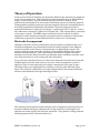
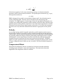
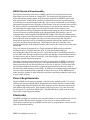
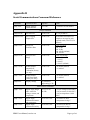
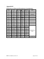
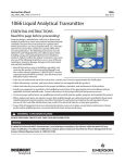
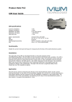
Electrical Resistivity Smart Sensor (ERSS) User Manual version 1.0 Table of Contents Theory of Operation Electrode Arrangement Polarity Temperature Effects Calibration ERSS Electrical Functionality 3 3 4 4 5 6 Power Requirements 6 Electrodes 6 User Configurable Parameters ID (I command) Bipolar Excitation Rate (P command) Input Gain Range (G command) Averaging Sample Size (N command) R8 Value (C command, option 0) Resistance Offset (C command, option 6) Calibration Factor (C command, option 1) Field Geometry Factor (C command, option 4) Temperature Calibration Offset (C command, option 3) Temperature Calibration Gain (C command, option 2) Self-Calibration Enable/Disable (U command - factory use only) FAST Step Mode Enable/Disable (F command - factory use only) 7 7 7 7 7 7 8 8 8 8 8 9 9 Measurement Range 9 Serial Communications 10 Appendix A Measurement Range and Resolution as a Function of User Configuration 11 Appendix B Serial Communications Command Reference 13 Appendix C Definition of Field Geometry Factor 15 Appendix D Equivalence of Electrical Resistivity to Conductivity 16 ERSS Users Manual, version 1.0 Page 2 of 16 Theory of Operation In theory, the electrical resistivity of a material is defined as the resistance per length for a unit cross-sectional area. This yields units of ohms multiplied by area and divided by length, or ohm-distance. Typical resistivity units are ohm-cm or ohm-m. While geophysicists and engineers are accustomed to thinking in terms of resistivity, physical oceanographers generally prefer the reciprocal property of electrical conductivity due to its directly proportional relationship with salinity. Electrical conductivity (EC) is expressed in Siemens (1/ohms) per unit length. A typical unit of EC is mS/cm. At 20°C, the conductivity of seawater is 48 mS/cm (0.048 S/cm). This corresponds to a resistivity of 20 Ω-cm (0.2 Ω-m). The ERSS reports resistivity in units of ohm-m. A table in Appendix D of this manual presents the equivalence between resistivity in ohm-m and conductivity expressed in several different units for values over a broad range. Electrode Arrangement Attempts to measure electrical conductivity of porous media or solutions using a twoelectrode arrangement are problematic because the voltage drop due to the medium must be measured on the same two electrodes that are supplying the current. This results in measuring the sum of the resistivity of the medium and that of the contact between electrodes and soil. This is particularly troublesome in highly electrolytic solutions, in which the induced current can stimulate surface chemistry reactions at the face of the electrodes to create scaling and other skin effects. In 1915, Wenner introduced the use of a linear four-electrode array that has become the standard approach in the earth sciences ever since. In this arrangement, current is applied to a pair of outer electrodes and voltage is measured across a pair of inner electrodes using a very high impedance voltmeter, as shown in the left-hand figure below. This results in a distribution of current and potential in the measured medium similar to that idealized in the right-hand figure below. The resistivity measurement using the Wenner-style arrangement at the boundary of a theoretical infinite half-space represents the average resistivity of a hemisphere of medium with radius equal to the electrode separation. The geometric scaling yields the following expression for electrical resistivity, ρ. ERSS Users Manual, version 1.0 Page 3 of 16 −1 ⎛ b ⎞ ρ = πbR⎜1 − ⎟ ⎝ b + a ⎠ In the above equation, b is the outer electrode separation, a is the inner electrode separation, and R is the measured resistance. For equally spaced electrodes (e.g., b=3a), this expression reduces to: € ρ = 2πaR ERSS is designed for use with a user-provided "Wenner-style" four-electrode array in contact with earth media. The user is free to decide the size and spacing of the electrodes. The ERSS supports a broad range of electrode spacings by allowing the user € to adjust user-configurable parameters, both in software and in the values chosen for two physical resistors on the printed circuit board. One of the software parameters is a Field Geometry Factor that in theory should equate to the value of 2πa in the above equation but can be set to any value that calibration data indicate is appropriate for the specific use. Polarity € In a medium bearing mobile chargeable molecules, specific attention must be given to the potential to induce electrophoresis and/or polarize the medium through application of DC current. For this reason, measurements of electrical conductivity of earth materials are generally conducted using low frequency alternating (sinusoidal) current or rapidly alternating DC current (step function), usually around 100 Hz, although frequencies anywhere between 20 and 1000 Hz have been reported in the literature. The ERSS applies a bi-polar excitation current to the medium, reversing the polarity of the current at a user-configurable rate of either 50, 100, or 200 Hz. The factory default frequency is 100 Hz. Temperature Effects The electrical conductivity (inverse of resistivity) of seawater and other materials, including marine sediments, varies with temperature. The chart below shows the magnitude of the temperature effect for seawater. ERSS Users Manual, version 1.0 Page 4 of 16 The ERSS measures and reports resistivity at the prevailing ambient temperature, which should be independently ascertained if the user desired to compute a temperature compensated resistivity value. The ERSS does not provide on-board temperature compensation because the relationship of resistivity to temperature varies as a function of the medium and, for many media, is not well known. If ERSS attempted temperature compensation it would be incorrect most of the time since it can neither sense what medium it is placed in nor know the relationship of resistivity to temperature in that medium. Calibration The ERSS reports measurements in user-selected units of either resistivity (ohm-m), resistance (ohm), or the hexadecimal integer value from the integral 24-bit analog-todigital converter (ADC). The reported value of resistance or resistivity is determined by application of a linear calibration equation that relates the integer output of the ADC to known values of resistors placed in contact with the electrodes and/or to known values the resistivity of aqueous KCl calibration solutions of known ionic strength. The ERSS stores its calibration equation and coefficients internally and applies them each time data are reported. Calibration parameters for determining series-equivalent resistance of the medium from the ADC output of current and voltage measurements include Resistance Offset and Resistance Gain. The series-equivalent resistance is multiplied by a linear Field Geometry Factor to yield the resistivity of the medium. Recommended practice for calibration is to use high precision resistors of known value to determine the Resistance Offset and Calibration Factor parameters for the internal ERSS circuitry and connection to the electrodes, and then to use liquid solutions of known resistivity to experimentally determine the Field Geometry Factor for the device in which the ERSS is installed. ERSS Users Manual, version 1.0 Page 5 of 16 ERSS Electrical Functionality The electrical resistivity smart sensor (ERSS) consists of an analog front end and a digital back end, both located on a single PCB. The analog front end produces and senses alternating polarity signals using H-bridges composed of MOSFET dual N and dual P transistors. A LM234Z IC produces a controlled current that is proportional to the resistance of a current setting resistor R7. This current is alternated via an H-bridge and passed through the outer electrodes of the Wenner array and a current sense resistor R8, which produces a nominal differential voltage of 2.5v used as the reference voltage for measuring the voltage drop across the inner electrodes of the Wenner array. An Analog Devices AD7730 IC digitizes the differential voltage produced across the inner Wenner electrodes, provides filtering of the digitized signal, and provides a pair of complementary control signals to the MOSFET H-bridges. The AD7730's measurement of voltage drop across the inner electrodes is ratiometric to the reference voltage which is derived directly from the applied current via current sense resistor R8. Therefore, thermal drift and other sources of instability potentially affecting the applied current source do not affect the measurement. All that must be known to infer the seriesequivalent resistance of the medium from the ADC result is the value of the current sense resistor R8. The 5-volt AD7730 is supervised by a Texas Instruments MSP430 microcontroller residing on the 3.3-v digital end of the PCB. A Texas Instruments MSP430 microcontroller controls the AD7730 via a 3-wire SPI interface. The MSP430 includes a serial UART which through a transceiver provides the RS-485 communications between the smart sensor and an external controller, such as data logger or personal computer running a terminal emulation program. Each time a measurement of electrical resistivity is reported by the ERSS, it consists of an arithmetic average (simple mean) of a user-specified number of samples (2 to 254) taken by the AD7730 at a user-specified rate of 50, 100, or 200 Hz. The user need only specify these parameters once prior to acquiring measurements as they are stored in internal non-volatile memory on the ERSS. In addition to averaging number and sample rate, the serial communications command set allows the user to set the ERSS address and to specify a number of other calibration and data acquisition parameters also stored in non-volatile memory. Power Requirements The basic ERSS board requires regulated 5-volt DC power applied to pads 1 (V+) and 4 (GND) of the position labeled JIN on the printed circuit board. However, some models are shipped with a Microchip MCP1702 LDO regulator wired to the power inputs at the pads labeled JIN on the board. This regulator will accept from 3 to 13 volts across the pre-wired red (V+) and black (GND) leads. The ERSS will draw a peak current of up to 25 mA while acquiring measurements. Electrodes The ERSS is designed to interface to the sensed medium via a user-supplied array of four equally-spaced (Wenner-style) electrodes. Users are free to determine their own electrode size and spacing, as the ERSS can and must be programmed to account for the effect of electrode geometry. ERSS Users Manual, version 1.0 Page 6 of 16 User Configurable Parameters Through the serial communications interface, the user has control of the parameters listed below. Refer to the section above on Theory of Operation for an understanding of these parameters. ID (I command) This parameter sets the ID of communications to which the ERSS will respond. The ID should be set only when a single ERSS is being communicated with and no other ERSS are on the RS-485 bus. The ID is a two-digit hexadecimal value. Both digits must be specified. ID 00 is reserved and all units will respond to commands issued to this ID, so it should likewise be used only with one ERSS on the RS-485 bus. Once a new ERSS ID is assigned, the unit will respond only to communications tagged with that ID and to 00, the global address. FF is also reserved, for communication directed at the controller. All units address their responses to ID FF. Bipolar Excitation Rate (P command) Bipolar Excitation rate is the frequency at which the ERSS reverses the polarity of the current it applies to the medium. It is the same frequency at which measurements of the medium's response to the applied current are also made. Each time the polarity is reversed, the sample of resistance obtained is actually the result of numerous Input Gain Range (G command) The Input Gain Range parameter adjusts the full-scale input range of the internal 24-bit analog-to-digital converter (ADC) in the ERSS. Higher resolution of measurements can be obtained at the expense of decreasing the maximum resistivity that can be measured by selecting a lower Input Gain Range. Values of 80, 40, and 20 millivolts are available. The factory default is 80 millivolts. Averaging Sample Size (N command) This is the integer number of samples of resistivity in the medium that are taken and averaged each time a measurement is reported. To cancel of any bias in the polarization state of the medium, an even number of samples is always processed, thereby ensuring that both excitation polarities are equally represented. Valid values include all even integers from 2 to 254. If the user specifies an odd integer for Averaging Sample Size, the embedded software rounds up to the next even number. Larger values than 254 can be specified but run the risk of accumulator overflow if the resistivity of the medium is at the high end of the measurement range. Users are advised not to set this parameter higher than 254, as that is the largest number of samples for which a correct response can be guaranteed when the resistivity of the medium is at the upper limit of the measurement range. R8 Value (C command, option 0) R8 Value is the value in ohms of the resistor labeled R8 on the ERSS printed circuit board that is used to sense the current that gets applied to the medium during measurement. Since users are free to change the physical component R8 to customize the measurement range and resolution of the ERSS, the user must specify the nominal value of R8 tot he embedded software. A nominal value is all that is needed, as the Calibration Factor accounts for any deviation from nominal in R8 as well as deviations in other electrical components on the board. The function of R8 and guidance for selecting ERSS Users Manual, version 1.0 Page 7 of 16 custom alternative values are discussed in the Measurement Range section of this manual. Resistance Offset (C command, option 6) The Resistance Offset parameter accounts for the amount of electrical resistance sensed by the ERSS that is dues to the internal electrical losses and the wiring to the Wenner electrode array regardless of the electrical resistivity of the medium. This resistance is in series with the medium and is thus additive with the series-equivalent resistance due to the resistivity of the medium. In reporting calibrated resistance values in ohms, the Resistance Offset is subtracted from the total resistance so the result reflects only the resistance across the electrodes. Calibration Factor (C command, option 1) The Calibration Factor accounts for the deviation from nominal values of R8 and other physical components in the ERSS measurement circuitry. The Calibration Factor is a linear factor multiplied by the theoretical series-equivalent resistance computed from the ratiometrically measured voltage drop across the inner electrodes to yield the actual series-equivalent resistance from which resistivity of the medium is then calculated by application of the Field Field Geometry Factor. Field Geometry Factor (C command, option 4) The Field Geometry Factor accounts for the geometry of the DC electrical field the sensor generates in the medium and gets multiplied by the measured series-equivalent resistance to yield the resistivity value reported by the ERSS. In theory, as discussed above, the Field Geometry Factor for equally spaced electrodes against an infinite half space should be 2πa in which a is the electrode spacing. In practice, the Field Geometry Factor often deviates slightly from theory due to the violation of theoretical assumptions. For example, the electrodes have a finite area in contact with the medium and the medium's 3D geometry does not match the idealization of an infinite half space. The € € experimentally user must determine the Field Geometry Factor for their own electrode array and application environment by first calibrating for resistance and then measuring resistance in a medium of known resistivity, and finally dividing the known resistivity of the medium by the ERSS-measured series-equivalent resistance to yield the Field Geometry Factor. Temperature Calibration Offset (C command, option 3) The ERSS includes a low-resolution temperature sensor on the printed circuit board available for monitoring the temperature of the electronics. It uses a 10-bit ADC and can resolve temperature differences of only about 0.3ºC. The offset is the temperature at which the voltage across the zener diode drops to zero. This theoretically corresponds to zero Kelvin, or -273.15ºC. Users are advised to ignore this setting. Temperature Calibration Gain (C command, option 2) This is the temperature response slope of the zener diode in degrees C per change in integer ADC value. Accounting for the on-board reference voltage and amplification of the temperature signal, this value comes out to about 0.3. It is precisely determined and entered into memory during factory calibration of the ERSS. Users are advised to ignore this setting. ERSS Users Manual, version 1.0 Page 8 of 16 Self-Calibration Enable/Disable (U command - factory use only) The AD7730 embedded in the ERSS has the ability to execute an internal self-calibration routine that compensates for minute changes in on-chip analog circuit behavior. This functionality is implemented for factory calibration and quality assurance purposes only. The user is cautioned against enabling internal self-calibration as enabling this functionality results in application of a unipolar excitation current to the medium for several milliseconds, which in a most media of geophysical interest introduces a polarity bias to subsequent measurements that requires a long period of continuous measurement to neutralize. In practice the user should never enable internal selfcalibration. In addition, the user has the option change discrete resistors on the ERSS printed circuit board to customize the measurement range and resolution according to the instructions in the Measurement Range section of this manual, below. FAST Step Mode Enable/Disable (F command - factory use only) The AD7730 embedded in the ERSS actually performs hundreds to thousands of samples of input voltage for each cycle in which the applied current polarity is reversed. Each "sample" thus utilized in the multi-sample average reported to the user (see Averaging Sample Size above) is actually the result of digital filtering performed on this high sampling rate data stream. FAST Step Mode Enable/Disable controls how the on-chip digital filtering algorithm compensates for rapid step changes in the input voltage. This functionality is implemented for factory use only, to configure the ERSS for applications in certain highly capacitive media. The factory default setting disables FAST Step mode and the user should not enable FAST Step Mode. A calibration performed with FAST Step Mode disabled will not be valid with FAST Step Mode enabled and vice versa. Measurement Range The measurement range of the ERSS is highly configurable through selection of the values of discrete resistors labeled R7 and R8 on the printed circuit board. R7 controls the amount of current applied to the medium through the user-supplied Wenner 4electrode array factory default. R8 controls the reference voltage applied to the on-board analog-to-digital converter (ADC) as a result of the applied current. The reference ADC voltage must be in the range of 1.9 to 2.6 volts. In the ERSS factory default configuration, the value of R7 is 681 ohms and that of R8 is 25.2 kilo-ohms. This combination results in a nominal excitation current of 98 microamps and an ADC input reference voltage of 2.46 volts. The excitation current, in micro-amps, is determined by the formula: Ie=66511/R7 The reference voltage, in volts, is: Vref=Ie/R8 In these two equations, R7 and R8 refer to the values of resistors R7 and R8, respectively. Metal film or thick film resistors with a temperature coefficient of less than 20ppm/°C ERSS Users Manual, version 1.0 Page 9 of 16 are recommended to ensure temperature stability of the electronics. The table in Appendix A shows the measurement range and resolution that will result from several combinations of values for R7, R8, Input Gain Range, and electrode separation distance. Serial Communications The ERSS communicates with a host data logger or computer via RS-485 serial communications, using a 2-wire interface. The baud rate is 9600 with 8 bits per byte, one stop bit, and no parity (9600, N, 8, 1). No other baud rates are supported at this time. All serial commands, their meanings, and syntax are listed in Appendix B: Serial Communications Command Reference. ERSS Users Manual, version 1.0 Page 10 of 16 Appendix A Measurement Range and Resolution as a Function of User Configuration User configurable parameters appear under italicized column headings. Factory default value appears against a gray background. The column representing the resolution of one bit in ohm-meters is the minimum possible electrical resistivity the sensor electronics can register. The last column represents the relative resolution in parts-per-million at the resistivity of standard seawater. R7, ohm R8, k-ohm I e, µA Vref Input Gain Range, mv Electrode Spacing, mm Max. Input Resistivity (ohm-m) Resolution of 1 bit (ohm-m) ppm resolution at 0.2083 ohm-m 2490 95 27 2.54 80 19 358 0.0000213 102 1330 50 50 2.50 80 19 191 0.0000114 55 681 25.2 98 2.46 80 19 98 0.0000058 28 412 15.4 161 2.49 80 19 59 0.0000035 17 300 11.3 222 2.51 80 19 43 0.0000026 12 2490 95 27 2.54 40 19 179 0.0000107 51 1330 50 50 2.50 40 19 95 0.0000057 27 681 25.2 98 2.46 40 19 49 0.0000029 14 412 15.4 161 2.49 40 19 30 0.0000018 8 300 11.3 222 2.51 40 19 22 0.0000013 6 100 4.53 665 3.01 40 19 7 0.0000004 2 2490 95 27 2.54 20 19 89 0.0000053 26 1330 50 50 2.50 20 19 48 0.0000028 14 681 25.2 98 2.46 20 19 24 0.0000015 7 412 15.4 161 2.49 20 19 15 0.0000009 4 300 11.3 222 2.51 20 19 11 0.0000006 3 2490 95 27 2.54 80 25 470 0.0000280 135 1330 50 50 2.50 80 25 251 0.0000150 72 681 25.2 98 2.46 80 25 129 0.0000077 37 412 15.4 161 2.49 80 25 78 0.0000046 22 300 11.3 222 2.51 80 25 57 0.0000034 16 2490 95 27 2.54 40 25 235 0.0000140 67 1330 50 50 2.50 40 25 126 0.0000075 36 681 25.2 98 2.46 40 25 64 0.0000038 18 ERSS Users Manual, version 1.0 Page 11 of 16 412 15.4 161 2.49 40 25 39 0.0000023 11 300 11.3 222 2.51 40 25 28 0.0000017 8 2490 95 27 2.54 20 25 118 0.0000070 34 1330 50 50 2.50 20 25 63 0.0000037 18 681 25.2 98 2.46 20 25 32 0.0000019 9 412 15.4 161 2.49 20 25 19 0.0000012 6 300 11.3 222 2.51 20 25 14 0.0000008 4 2490 95 27 2.54 80 50 941 0.0000561 269 1330 50 50 2.50 80 50 503 0.0000300 144 681 25.2 98 2.46 80 50 257 0.0000153 74 412 15.4 161 2.49 80 50 156 0.0000093 45 300 11.3 222 2.51 80 50 113 0.0000068 32 2490 95 27 2.54 40 50 470 0.0000280 135 1330 50 50 2.50 40 50 251 0.0000150 72 681 25.2 98 2.46 40 50 129 0.0000077 37 412 15.4 161 2.49 40 50 78 0.0000046 22 300 11.3 222 2.51 40 50 57 0.0000034 16 2490 95 27 2.54 20 50 235 0.0000140 67 1330 50 50 2.50 20 50 126 0.0000075 36 681 25.2 98 2.46 20 50 64 0.0000038 18 412 15.4 161 2.49 20 50 39 0.0000023 11 300 11.3 222 2.51 20 50 28 0.0000017 8 ERSS Users Manual, version 1.0 Page 12 of 16 Appendix B Serial Communications Command Reference Command Function/Action Response Value [id]V<CR> Report software version number FF:x<CR> x=software version number Setup Commands [id]I aa<CR> Set sensor ID FF:OK<CR> aa=1-byte address [id]N hh<CR> Set Averaging Sample Size FF:OK<CR> hh=hexadecimal number of samples to average for each reported result, 02 to FE (254 decimal) [id]P h<CR> Set Bipolar Excitation Rate FF:OK<CR> Value of h: Rate 800: 25 Hz 400: 50 Hz 200: 100 Hz (default) 100: 200 Hz [id]G h<CR> Set Input Gain Range FF:OK<CR> Value of h: Range 0: ±10 mV 1: ±20 mV 2: ±40 mV 3: ±80 mV (default) [id]U v<CR> Enable/Disable Internal SelfCalibration (factory use only) FF:OK<CR> v=0 disable (default) v=1 enabled [id]F v<CR> Enable/Disable FAST Step Mode (factory use only) FF:OK<CR> v=0 disable (default) v=1 enabled [id]D<CR> Display settings FF:[formatted output string]<CR> Measurement Commands [id]S 1<CR> Report single integer ADC values for voltage, current, and temperature FF:vvvvvv iiii tttt<CR> v=3-byte voltage (24-bit ADC) i=2-byte current (10-bit ADC) t=2-byte temperature (10-bit ADC) [id]S 3<CR> Report single calibrated resistance and temperature FF:rrr.rrrrrr, tt.ttt r=resistance in ohms t=temperature in deg C [id]S 4<CR> Report single calibrated resistivity FF:rrr.rrrrrr, tt.ttt r=resistivity in ohm-m t=temperature in deg C ERSS Users Manual, version 1.0 Page 13 of 16 and temperature [id]M 1<CR> Stream measurements of integer ADC values for voltage, current, and temperature FF:vvvvvv iiii tttt<CR> (repeatedly) v=3-byte voltage (24-bit ADC) i=2-byte current (10-bit ADC) t=2-byte temperature (10-bit ADC) [id]M 3<CR> Stream calibrated resistance and temperature FF:rrr.rrrrrr, tt.ttt<CR> (repeatedly) r=resistance in ohms t=temperature in deg C [id]M 4<CR> Stream calibrated resistivity and temperature FF:rrr.rrrrrr, tt.ttt<CR> (repeatedly) r=resistivity in ohm-m t=temperature in deg C [id]M 0<CR> Stop streaming data FF:OK<CR> r=resistivity in ohm-m t=temperature in deg C Calibration Commands [id]C 0 x<CR> Set value of R8 FF:OK<CR> x=resistance of R8 in ohms [id]C 1 x<CR> Set Calibration Factor FF:OK<CR> x=Calibration Factor [id]C 2 x<CR> Set Temperature Gain FF:OK<CR> x=Temperature Gain (deg C/mA) [id]C 3 x<CR> Set Temperature Offset FF:OK<CR> x=Temperature Offset (deg C) [id]C 4 x<CR> Set Field Geometry Factor FF:OK<CR> x=Field Geometry Factor [id]C 5 x<CR> Set value of R11 FF:OK<CR> x=R11 resistance (ohms) [id]C 6 x<CR> Set Resistance Offset FF:OK<CR> x=Resistance Offset (ohms) [id]B<CR> Display all coefficients set using C command FF:[formatted output string]<CR> x=Resistance Offset (ohms) The hardware protocol is two-wire RS-485. Communications parameters are: 9600 baud, no parity, 8 bits per word, 1 stop bit. The command terminator is an ASCII carriage return "<CR>" (Hex 0D, Decimal 13) Each sensor has a 2-byte ID. All commands begin with a sensor ID. 00 is reserved ID. All sensors respond to ID 00 regardless of their individually assigned ID. To avoid data collisions, this ID should only be used when only one sensor is attached to the RS-485 bus. ERSS Users Manual, version 1.0 Page 14 of 16 Appendix C Definition of Field Geometry Factor ASTM standard G57-06 gives the following equation for computing the resistivity of a soil medium from the measured resistance and electrode spacing using an equally spaced Wenner style four-electrode array in a homogenous half space (current is assumed to flow evenly through a hemispherical volume of soil with radius equal to the electrode spacing): ρ = 2πaR where: R is the resistance (ohms) € (m) a is the electrode spacing ρ is the resistivity (ohm-m) The ASTM standard indicates that the resistance R to be used is the voltage drop V across the inner electrodes divided by the current I applied to the outer electrodes, resulting in a reformulation of the above equation as: ρ = 2πa V I This is notably consistent with a solution derived by Avants et al (1999)1. € Avants, B., Soodak, D., Ruppeiner, G., “Measuring the Electrical Conductivity of the Earth,” American Journal of Physics. 67 (7), July 1999. See equation (8) in the cited reference. 1 ERSS Users Manual, version 1.0 Page 15 of 16 Appendix D Equivalence of Electrical Resistivity to Conductivity S/m S/cm mS/cm µS/cm ohm-m 7 0.07 70 70000 0.14 5 0.05 50 50000 0.2 4.8 0.048 48 48000 0.2083 2 0.02 20 20000 0.5 1 0.01 10 10000 1 0.5 0.005 5 5000 2 0.2 0.002 2 2000 5 0.1 0.001 1 1000 10 0.05 0.0005 0.5 500 20 0.02 0.0002 0.2 200 50 0.01 0.0001 0.1 100 100 0.005 0.00005 0.05 50 200 0.002 0.00002 0.02 20 500 0.001 0.00001 0.01 10 1000 0.0005 0.000005 0.005 5 2000 0.0003 0.000003 0.003 3 3333 0.0002 0.000002 0.002 2 5000 0.0001 0.000001 0.001 1 10000 0.00005 0.0000005 0.0005 0.5 20000 ERSS Users Manual, version 1.0 Note Seawater Drinking Water Range De-Ionized H2O Page 16 of 16