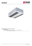
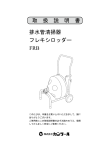
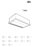
1
SWH
SE ... 21
GB ... 24
NO ... 27
FI ... 30
DE ... 33
PL ... 40
RU ... 43
ES ... 47
NL ... 50
IT ... 53
FR ... 37
SWH
Fan heater SWH
1 Fan heater SWH
2 Mounting brackets SWB
3 Basic filter SWFTN
4 Filter section,
deep-pleated bagfilter EU3
SWF
5 Return air intake SWD
6 Mixing cabinet with damper
SWBS
7 Outer wall grill SWY
8 Extra air director, adjustable louvres SWLR
1
2
3
4
5
6
7
8
3
2
7
Fläktluftvärmare SWH
Monteringskonsoler SWB
Trådnätsfilter SWFTN
Filterskåp, djupveckad
filterkasset EU3 SWF
Distansdel för filterskåp SWD
Blandningsskåp med spjäll SWBS
Ytterväggsgaller SWY
Extra luftriktare, ställbara lameller SWLR
6
4
5
1
Type
Description
RSK-nr
NRF-nr
SWB0
SWB1
SWB2
SWB3
SWFTN02
SWFTN1
SWFTN2
SWFTN3
SWF1
SWF2
SWF3
SWEF1
SWEF2
SWEF3
SWD1
SWD2
SWD3
SWBS1
SWBS2
SWBS3
SWY1
SWY2
SWY3
SWLR1
SWLR2
SWLR3
Mounting brackets SWH02
Mounting brackets SWH12
Mounting brackets SWH22
672 49 10
672 49 11
672 49 12
85 023 14
85 023 15
85 023 16
Mounting brackets SWH32/SWH33
Basic filter SWH02
Basic filter SWH12
Basic filter SWH22
Basic filter SWH32/SWH33
Filter section SWH12
Filter section SWH22
Filter section SWH32/SWH33
Extra filter cassette EU3 SWH12
Extra filter cassette EU3 SWH22
Extra filter cassette EU3 SWH32/SWH33
Return air intake SWH12
Return air intake SWH22
Return air intake SWH32/SWH33
Mixing cabinet SWH12
Mixing cabinet SWH22
Mixing cabinet SWH32/SWH33
Outer wall grille SWH12
Outer wall grille SWH22
Outer wall grille SWH32/SWH33
Extra air director sideways SWH12
Extra air director sideways SWH22
Extra air director sideways SWH32/SWH33
672 49 13
673 03 95
673 03 96
673 03 97
673 03 98
672 70 14
672 70 15
672 70 16
672 70 17
672 70 18
672 70 19
672 70 20
672 70 21
672 70 22
672 70 08
672 70 09
672 70 10
672 70 11
672 70 12
672 70 13
672 70 26
672 70 27
672 70 28
85 023 17
2
SWB
SWFTN
85 021 32
85 021 33
85 021 34
85 021 35
85 021 36
85 021 37
SWF
SWD
SWBS
SWY
SWH
Dimensions
K
F
G
Inlet
A
I
H
Outlet
ø
B
C
D
Type
A
[mm]
B
[mm]
J
E
C
[mm]
D
[mm]
E
[mm]
F
[mm]
G
[mm]
H
[mm]
I
[mm]
J
[mm]
K
[mm]
Ø
[mm]
SWH02
525
515
320
40
95
70
70
390
405
260
70
22
SWH12
600
535
340
70
95
70
70
465
470
260
70
22
SWH22
725
680
370
50
100
70
70
585
580
400
75
28
SWH32/33
850
820
450
75
100
70
70
710
700
530
75
28
Mounting brackets SWB
Filter section, SWF
E
Outer wall grill, SWY
I
55
L
25
D
D
F
G
ø20
50
C
B
K
288
H
42,3
A
25
Type
A
B
C
D
[mm]
[mm]
[mm]
[mm]
405
235
10
SWB0 195
Type
SWF1
E
F
G
H
I
[mm]
[mm]
[mm]
[mm]
[mm]
466
492
470
444
524
Type
K
SWY1
L
[mm]
[mm]
500
400
SWB1 195
470
300
10
SWF2
616
602
580
594
524
SWY2
600
600
SWB2 250
580
410
10
SWF3
746
722
700
724
524
SWY3
800
700
SWB3 335
700
530
10
Return air intake, SWD
Mixing cabinet with damper, SWBS
J
G
A
60
J
ø13,2
E
L
K
C
F
B
ø20
50
122
D ø10(8x)
Type
SWBS1
M
H
A
B
C
D
E
F
G (ø)
H
J
[mm]
[mm]
[mm]
[mm]
[mm]
[mm]
[mm]
[mm]
[mm]
502
600
578
480
422
448
320
564
97
Type
SWD1
J
K
L
[mm]
[mm]
[mm]
M
[mm]
466
492
470
444
SWBS2
702
702
680
680
572
558
405
672
109
SWD2
616
602
580
594
SWBS3
802
902
880
780
702
678
504
772
114
SWD3
746
722
700
724
3
SWH
Control SWH
SIRe Basic
SIRe Competent
C
Modular cables
PE N L
SUPPLY 230V
SIReUB1,
control unit Basic
X4
C1
X3
ROOM
ACTUATOR
230V
Integrated
control card
Base in SWH
Modular cable
SIReUA1,
control unit
Competent and
Advanced
PE N L
SUPPLY 230V
SIReC1X,
control card HUB
Integrated control
Competent
card Base in SWH
0
90
0
For Advanced with
mixing cabinet SIReFAWM also
includes damper
motor SMM24 and
clamp-on sensor
SIReWTA.
SIRe Advanced
X3
ROOM
X4
C1
X5
C2
90
X5
C2
60
30
30
60
PE N L
SUPPLY 230V
X5
C2
SIReUA1,
control unit
Competent and
Advanced
4
SIReA1X,
control card
HUB Advanced
X4
C1
X3
ROOM
ACTUATOR
230V
Integrated
control card
Base in SWH
Modular cables
SIReOTX,
outdoor temperature
sensor
Type
RSK-nr
EL-nr
Description
SIReB
SIReFC
SIReFA
SIReFAWM
SIReRTX
SIReWTA
SIReUR
SIReCJ4
SIReCJ6
SIReCC603
SIReCC605
SIReCC610
SIReCC615
SIReCC403
SIReCC405
SIReCC410
SIReCC415
673 09 57
49 306 01
Control system SIRe Basic
673 09 59
673 09 61
673 09 63
673 09 22
49 306 03
49 306 05
49 306 08
Control system SIRe Competent
Control system SIRe Advanced
Control system SIRe Advanced with mixing cabinett
External room temperature sensor
Clamp-on sensor
Kit for recessed installation
Used to join two RJ11(4/4)
Used to join two RJ12 (6/6)
Modular cable RJ12
Modular cable RJ12
Modular cable RJ12
Modular cable RJ12
Modular cable RJ11
Modular cable RJ11
Modular cable RJ11
Modular cable RJ11
673 09 21
673 09 23
673 09 24
673 09 25
673 09 26
673 09 27
673 09 28
673 09 29
673 09 30
SMM24,
damper
motor
L (m)
3m
5m
10 m
15 m
3m
5m
10 m
15 m
ACTUATOR
230V
SWH
VMO
SDM24
TBVCM
AV
VMOP
SDM24
TBVCMP
AV
VOS
SD230
TBVC
BPV10
AV
SD230
VOSP
TBVCMP
BPV10
AV
VOT
SD230
TRVS
VMT
SDM24
TRVS
5
SWH
Type
RSK-nr
Description
Flow
Voltage Connection Kvs
[V]
VMO15LF
VMO15NF
VMO20
VMO25
VMOP15LF
VMOP15NF
VMOP20
VMOP25
VOS15LF
VOS15NF
VOS20
VOS25
VOSP15LF
VOSP15NF
VOSP20
VOSP25
VOT15
VOT20
VOT25
VMT15
VMT20
VMT25
673 09 47
673 09 48
673 09 49
673 09 50
673 09 51
673 09 52
673 09 53
673 09 54
673 09 35
673 09 36
673 09 37
673 09 38
673 09 43
673 09 44
673 09 45
673 09 46
Modulating valve kit
Modulating valve kit
Modulating valve kit
Modulating valve kit
Pressure independent and modulating valve kit
Pressure independent and modulating valve kit
Pressure independent and modulating valve kit
Pressure independent and modulating valve kit
Valve kit on/off
Valve kit on/off
Valve kit on/off
Valve kit on/off
Pressure independent valve kit
Pressure independent valve kit
Pressure independent valve kit
Pressure independent valve kit
Three way valve and actuator on/off
Three way valve and actuator on/off
Three way valve and actuator on/off
Three way valve and modulating actuator
Three way valve and modulating actuator
Three way valve and modulating actuator
Low flow
Normal flow
Normal flow
Normal flow
Low flow
Normal flow
Normal flow
Normal flow
Low flow
Low flow
Normal flow
Normal flow
Low flow
Normal flow
Normal flow
Normal flow
24 V
24 V
24 V
24 V
24 V
24 V
24 V
24 V
230 V
230 V
230 V
230 V
230 V
230 V
230 V
230 V
6
DN15
DN15
DN20
DN25
DN15
DN15
DN20
DN25
DN15
DN15
DN20
DN20
DN15
DN15
DN20
DN25
DN15
DN20
DN25
DN15
DN20
DN25
0,40
1,0
2,0
4,0
0,90
1,8
3,4
7,2
-
SWH
Wiring diagrams SWH
Internal
SWH02-22
M
~
Yellow-green
White
Blue
Black
Brown
Yellow
Yellow
Transformer
N
SWH02
SWH12 SWH22
F1
F2
F3
F4
F5
80 V
100 V
125 V
150 V
230 V
100 V
125 V
150V
165V
230 V
TB TB Z1U2 U1 Z2 PE
100 V
125 V
140V
150V
230 V
Transformer
F5 F4 F3 F2 F1 N N
MOTOR / TRAFO
L
H2 H1 N
HEATING
N
230 V
*
80 V
100 V
125 V
140 V
150 V
165 V
80 V
100 V
125 V
140 V
150 V
165 V
230 V
*
Orange
Brown
Blue
Black
White
~
Yellow-green
M
SWH32-33
F5 F4 F3 F2 F1 N N
MOTOR / TRAFO
B1
L
H2 H1 N
HEATING
B1
MOTOR
INTERNAL
PROTECTION SENSOR
MOTOR
INTERNAL
PROTECTION SENSOR
N L~ L
C2
C1
ROOM
ACTUATOR
230V
PE N L
SUPPLY
230V
N L~ L
C2
C1
ROOM
ACTUATOR
230V
PE N L
SUPPLY
230V
7
8
X4
C1
B1
SUPPLY 230V
L N PE
N
N H1 H2
HEATING
PE L
ACTUATOR
230V
L
N
C1
X4
X3
ROOM
N F1 F2 F3 F4 F5
MOTOR / TRAFO
ROOM
X3
SIReB1 Internal
SIRe Basic
X5
C2
SIReB1
C2
X5
PE N L
SUPPLY 230V
ACTUATOR
230V
MOTOR
INTERNAL
PROTECTION SENSOR
Parallell connection
X5
C2
SIReB1
SIReSD230
X4
C1
X3
ROOM
PE N L
SUPPLY 230V
ACTUATOR
230V
X5
C2
SIReB1
X4
C1
X3
ROOM
SIReSD230
PE N L
SUPPLY 230V
ACTUATOR
230V
SIReRTX
(optional)
SIReSD230
C
SIReUB1
SIReRTX
(optional)
C
SIReUB1
SWH
Wiring diagrams SWH
15 161718
1112
+ 7 8 9 10
EXTERNAL ON/OFF
5-30V AC/DC
EXTERNAL ALARM IN
(potential free contact)
EXTERNAL SETBACK TEMP.
ON/OFF (potential free contact)
COM 1
C1
X4
C2
Pot.
X5
Unit ID
SIReB1
SIRe Competent
X5
C2
X4
C1
ROOM
X3
X3
ROOM
~
N L L
PE N
PE N L
SUPPLY 230V
ACTUATOR
230V
L
SIReSD230
SIReC1X
ALARM OUT (BMS)
(potential free contact,
max 3A, 230V)
EXTERNAL RPM 0-10V DC IN
COM 2
ROOM
19 20
SIReRTX
(optional)
SIReUA1
SWH
9
SIRe Advanced
SWH
10
SIRe Advanced with mixing cabinet
SWH
11
SWH
Technical specifications |  2
Fan heater SWH with water heat
Type
RSK-nr
Heat output *1
[kW]
Air flow*2
[m³/h]
Air flow*2
[m³/s]
Sound level*2,3
[dB(A)]
∆t*1,4
[°C]
SWH02
SWH12
SWH22
SWH32
SWH33
672 68 79
672 68 89
672 68 99
672 69 09
672 69 19
12
20
33
51
66
530 - 1120
840 - 1810
1470 - 3260
2870 - 5860
2625 - 5420
0,15 - 0,31
0,23 - 0,50
0,41 - 0,91
0,80 - 1,63
0,73 - 1,51
26 - 39
31 - 48
29 - 55
41 - 58
41 - 58
28
22
23
23
31
Type
Air throw*5
[m]
Water
volume*6
[l]
Voltage
[V]
Amperage
[A]
HxWxD
[mm]
Weight
[kg]
SWH02
SWH12
SWH22
SWH32
SWH33
4
8
10
12
11
1,3
1,5
2,7
3,8
5,2
230 V~
230 V~
230 V~
230 V~
230 V~
0,34
0,64
1,12
2,12
2,13
525x515x320
600x535x340
725x680x370
850x820x450
850x820x450
15
19
27
46
46
*1) Applicable at water temperature 80/60 °C, air temperature, in +15 °C.
*2) Applies to fan position 1 – 4.
*3) Conditions: Distance to the unit 5 metres. Directional factor: 2. Equivalent absorption area: 200 m².
*4) ∆t = temperature rise of passing air at maximum heat output and highest airflow.
*5) The air throw data above is valid for highest airflow when the horizontally adjustable air director is used
and the outlet temperature is +40 °C and the room temperature is +18 °C. The air throw is defined as the
distance in a straight angle from the fan heater to the pointwhere the air speed has dropped to 0,2 m/s.
*6) Water volume inside battery.
CE compliant.
Protection class: IPX4.
12
SWH33
SWH32
SWH22
SWH12
SWH02
Type
Max
4
3
2
1
Max
4
3
2
1
Max
4
3
2
1
Max
4
3
2
1
Max
4
3
2
1
0,35
0,31
0,27
0,20
0,15
0,75
0,50
0,42
0,31
0,23
1,17
0,91
0,77
0,59
0,41
1,84
1,63
1,33
1,08
0,80
1,71
1,51
1,25
1,00
0,73
[m³/s]
Fan
Airflow
position
26,3
24,4
22,4
18,4
14,7
42,1
33,6
30,3
25,1
20,7
69,7
60,3
54,6
46,6
36,4
109,0
101,0
90,2
79,6
65,6
142,0
131,0
116,0
99,8
79,4
40
42
45
51
57
26
34
37
43
49
29
33
37
42
50
28
30
34
38
45
46
48
53
57
64
0,11
0,10
0,09
0,08
0,06
0,17
0,14
0,13
0,10
0,09
0,29
0,25
0,23
0,19
0,15
0,45
0,42
0,37
0,33
0,27
0,59
0,54
0,48
0,41
0,33
3,8
3,3
2,8
2,0
1,3
2,8
1,9
1,6
1,1
0,8
3,9
3,0
2,5
1,9
1,2
5,5
4,8
3,9
3,1
2,2
9,9
8,5
6,8
5,2
3,4
21,7
20,1
18,5
15,1
12,1
34,7
27,6
24,8
20,6
16,9
57,6
49,7
45,0
38,3
29,9
89,8
83,7
74,4
65,6
53,9
117,0
108,0
95,7
82,2
65,2
48
50
52
57
63
36
42
45
50
56
38
42
45
50
56
38
40
43
47
52
53
55
59
63
69
0,09
0,08
0,08
0,06
0,05
0,14
0,11
0,10
0,09
0,07
0,24
0,21
0,19
0,16
0,12
0,37
0,34
0,31
0,27
0,22
0,48
0,45
0,39
0,34
0,27
Incoming / outgoing water temperature 130/70 °C
Air temp. in = -15 °C
Air temp. in = 0 °C
Output Air
Water
Pressure Output Air.
Water
temp.
flow
drop
temp.
flow
out
out
[kW]
[°C]
[l/s]
[kPa]
[kW]
[°C]
[l/s]
2,7
2,3
2,0
1,4
0,9
2,0
1,3
1,1
0,8
0,5
2,8
2,1
1,8
1,3
0,8
3,9
3,4
2,7
2,2
1,5
6,9
6,0
4,8
3,6
2,4
17,3
16,0
14,7
12,0
9,6
27,5
21,9
19,7
16,3
13,3
45,9
39,6
35,8
30,4
23,7
71,7
66,8
59,2
52,2
42,8
93,6
86,2
76,2
65,4
52,0
55
57
59
63
68
45
50
53
57
61
47
50
53
57
62
47
48
51
54
59
59
61
64
68
73
0,07
0,07
0,06
0,05
0,04
0,11
0,09
0,08
0,07
0,06
0,19
0,16
0,15
0,13
0,10
0,30
0,28
0,24
0,22
0,18
0,39
0,36
0,31
0,27
0,21
Air temp. in = +15 °C
Pressure Output Air.
Water
drop
temp.
flow
out
[kPa]
[kW]
[°C]
[l/s]
1,8
1,5
1,3
0,9
0,6
1,3
0,9
0,7
0,5
0,3
1,8
1,4
1,2
0,9
0,5
2,6
2,2
1,8
1,4
1,0
4,6
3,9
3,1
2,4
1,6
[kPa]
Pressure
drop
SWH
Output charts water
13
14
SWH33
SWH32
SWH22
SWH12
SWH02
Type
Max
4
3
2
1
Max
4
3
2
1
Max
4
3
2
1
Max
4
3
2
1
Max
4
3
2
1
0,35
0,31
0,27
0,20
0,15
0,75
0,50
0,42
0,31
0,23
1,17
0,91
0,77
0,59
0,41
1,84
1,63
1,33
1,08
0,80
1,71
1,51
1,25
1,00
0,73
[m³/s]
Fan
Airflow
position
26,9
25,0
22,9
18,7
14,9
44,2
35,1
31,6
26,1
21,3
72,4
62,5
56,4
48,0
37,3
112,0
105,0
93,1
82,0
67,3
145,0
133,0
118,0
101,0
80,0
41
43
46
52
58
28
36
39
45
52
30
35
39
44
52
29
32
36
40
46
47
49
53
58
65
0,22
0,21
0,19
0,15
0,12
0,36
0,29
0,26
0,22
0,18
0,60
0,51
0,46
0,40
0,31
0,93
0,86
0,77
0,68
0,55
1,19
1,10
0,97
0,83
0,66
13,8
12,1
10,3
7,2
4,7
11,1
7,3
6,0
4,2
2,9
15,0
11,4
9,5
7,1
4,5
21,0
18,5
14,8
11,7
8,2
36,3
31,1
24,6
18,8
12,3
22,4
20,7
19,0
15,5
12,3
36,8
29,2
26,2
21,6
17,6
60,3
51,9
46,9
39,8
30,8
93,7
87,3
77,4
68,1
55,7
120,0
111,0
97,5
83,5
66,0
49
51
54
59
64
38
45
48
53
58
40
44
47
52
58
39
41
45
48
54
54
56
60
64
70
0,18
0,17
0,16
0,13
0,10
0,30
0,24
0,22
0,18
0,15
0,50
0,43
0,39
0,33
0,25
0,77
0,72
0,64
0,56
0,46
0,99
0,91
0,80
0,69
0,54
Incoming / outgoing water temperature 110/80 °C
Air temp. in = -15 °C
Air temp. in = 0 °C
Output Air
Water
Pressure Output Air.
Water
temp.
flow
drop
temp.
flow
out
out
[kW]
[°C]
[l/s]
[kPa]
[kW]
[°C]
[l/s]
9,9
8,6
7,3
5,1
3,3
7,9
5,2
4,2
3,0
2,1
10,7
8,1
6,7
5,0
3,1
15,0
13,2
10,5
8,3
5,8
25,8
22,2
17,6
13,2
8,6
18,1
16,7
15,3
125,0
9,9
29,7
23,5
21,0
17,3
14,1
48,8
41,9
37,8
32,0
24,8
75,9
70,6
62,5
54,9
44,9
96,9
89,2
78,5
67,1
52,9
57
59
61
65
69
47
53
55
60
64
49
53
55
59
64
48
50
53
56
61
61
63
66
69
74
0,15
0,14
0,13
0,10
0,08
0,24
0,19
0,17
0,14
0,12
0,40
0,35
0,31
0,26
0,20
0,63
0,58
0,51
0,45
0,37
0,80
0,73
0,65
0,55
0,44
Air temp. in = +15 °C
Pressure Output Air.
Water
drop
temp.
flow
out
[kPa]
[kW]
[°C]
[l/s]
6,7
5,8
5,0
3,4
2,2
5,4
3,5
2,8
2,0
1,4
7,3
5,5
4,5
3,4
2,1
10,2
8,9
7,1
5,6
3,9
17,4
14,9
11,8
8,9
5,7
[kPa]
Pressure
drop
SWH
Output charts water
SWH33
SWH32
SWH22
SWH12
SWH02
Type
Max
4
3
2
1
Max
4
3
2
1
Max
4
3
2
1
Max
4
3
2
1
Max
4
3
2
1
0,35
0,31
0,27
0,20
0,15
0,75
0,50
0,42
0,31
0,23
1,17
0,91
0,77
0,59
0,41
1,84
1,63
1,33
1,08
0,80
1,71
1,51
1,25
1,00
0,73
[m³/s]
Fan
Airflow
position
23,4
21,7
19,9
16,3
12,9
38,7
30,7
27,6
22,8
18,6
63,2
54,5
49,2
41,9
32,5
98,1
91,5
81,2
71,7
58,6
126,0
116,0
102,0
87,8
69,5
34
36
38
43
49
23
29
33
38
43
50
29
32
36
43
24
26
29
33
38
39
41
45
49
54
0,29
0,27
0,24
0,20
0,16
0,47
0,38
0,34
0,28
0,23
0,77
0,67
0,60
0,51
0,40
1,20
1,12
0,99
0,88
0,72
1,54
1,42
1,25
1,08
0,85
23,0
20,0
17,1
11,8
7,8
18,7
12,2
10,0
7,1
4,9
25,0
19,0
15,8
11,7
7,4
35,1
30,9
24,7
19,6
13,6
60,4
52,0
41,3
31,2
20,3
19,0
17,6
16,1
13,1
10,4
31,4
24,9
22,3
18,4
15,0
51,4
44,2
39,9
33,8
26,2
79,8
74,3
65,8
57,7
47,4
102,0
93,8
82,7
70,8
55,9
42
44
46
50
54
32
38
41
45
49
34
38
40
44
49
33
35
38
41
46
46
48
51
54
59
0,23
0,22
0,20
0,16
0,13
0,38
0,30
0,27
0,23
0,18
0,63
0,54
0,49
0,41
0,32
0,98
0,91
0,81
0,71
0,58
1,25
1,15
1,01
0,87
0,68
Incoming / outgoing water temperature 90/70 °C
Air temp. in = -15 °C
Air temp. in = 0 °C
Output Air
Water
Pressure Output Air.
Water
temp.
flow
drop
temp.
flow
out
out
[kW]
[°C]
[l/s]
[kPa]
[kW]
[°C]
[l/s]
15,7
13,6
11,6
8,1
5,3
12,7
8,3
6,8
4,8
3,3
17,1
13,0
10,7
8,0
5,0
24,0
21,0
16,8
13,3
9,2
41,0
35,2
27,9
21,0
13,6
14,8
13,7
12,5
10,2
8,1
24,4
19,3
17,3
14,2
11,6
40,1
34,4
31,0
26,3
20,3
62,3
58,0
51,3
45,0
36,7
79,4
73,0
64,3
54,9
43,3
49
51
52
56
59
42
46
48
52
55
43
46
48
51
55
43
44
46
49
52
53
54
57
59
63
0,18
0,17
0,15
0,12
0,10
0,30
0,24
0,21
0,17
0,14
0,49
0,42
0,38
0,32
0,25
0,76
0,71
0,63
0,55
0,47
0,97
0,89
0,79
0,67
0,53
Air temp. in = +15 °C
Pressure Output Air.
Water
drop
temp.
flow
out
[kPa]
[kW]
[°C]
[l/s]
10,0
8,6
7,3
5,1
3,3
8,0
5,2
4,2
3,0
2,0
10,8
8,2
6,8
5,0
3,1
15,2
13,3
10,6
8,4
5,7
25,9
22,2
17,6
13,2
8,5
[kPa]
Pressure
drop
SWH
Output charts water
15
16
SWH33
SWH32
SWH22
SWH12
SWH02
Type
Max
4
3
2
1
Max
4
3
2
1
Max
4
3
2
1
Max
4
3
2
1
Max
4
3
2
1
0,35
0,31
0,27
0,20
0,15
0,75
0,50
0,42
0,31
0,23
1,17
0,91
0,77
0,59
0,41
1,84
1,63
1,33
1,08
0,80
1,71
1,51
1,25
1,00
0,73
[m³/s]
Fan
Airflow
position
20,7
19,2
17,6
14,4
11,4
34,0
27,0
24,2
20,0
16,4
55,7
48,0
43,4
36,9
28,7
86,4
80,6
71,5
63,0
51,7
111,0
102,0
90,5
77,7
61,6
28
30
32
37
41
18
24
27
31
36
20
24
26
30
36
19
21
24
27
32
32
34
38
41
46
0,25
0,23
0,21
0,18
0,14
0,41
0,33
0,30
0,24
0,20
0,68
0,58
0,53
0,45
0,35
1,05
0,98
0,87
0,77
0,63
1,35
1,25
1,10
0,95
0,75
18,7
16,3
13,9
9,7
6,4
15,0
9,8
8,1
5,7
3,9
20,2
15,4
12,8
9,5
6,0
28,2
24,8
19,9
15,8
11,0
48,9
42,1
33,5
25,3
16,5
16,3
15,1
13,9
11,3
9,0
26,8
21,3
19,1
15,7
12,8
44,0
37,9
34,2
29,1
22,5
68,4
63,8
56,5
49,7
40,7
87,7
80,8
71,3
61,1
48,3
36
37
39
43
47
28
33
35
39
42
29
32
34
38
42
29
30
33
35
39
40
41
44
47
51
0,20
0,18
0,17
0,14
0,11
0,33
0,26
0,23
0,19
0,16
0,54
0,46
0,42
0,35
0,27
0,83
0,78
0,69
0,61
0,50
1,07
0,98
0,87
0,74
0,59
Incoming / outgoing water temperature 80/60 °C
Air temp. in = -15 °C
Air temp. in = 0 °C
Output Air
Water
Pressure Output Air.
Water
temp.
flow
drop
temp.
flow
out
out
[kW]
[°C]
[l/s]
[kPa]
[kW]
[°C]
[l/s]
12,2
10,6
9,0
6,3
4,1
9,7
6,3
5,2
3,6
2,5
13,1
10,0
8,3
6,1
3,9
18,4
16,1
12,9
10,2
7,1
31,7
27,2
21,6
16,3
10,6
12,2
11,3
10,3
8,4
6,7
20,0
15,8
14,2
11,7
9,5
32,9
28,3
25,5
21,7
16,8
51,2
47,7
42,2
37,1
30,3
65,7
60,4
53,3
45,6
36,0
43
45
46
49
52
37
41
42
45
48
38
40
42
45
48
38
39
41
43
46
46
48
50
52
55
0,15
0,14
0,13
0,10
0,08
0,24
0,19
0,17
0,14
0,12
0,40
0,34
0,31
0,26
0,20
0,62
0,58
0,51
0,45
0,37
0,80
0,74
0,65
0,55
0,44
Air temp. in = +15 °C
Pressure Output Air.
Water
drop
temp.
flow
out
[kPa]
[kW]
[°C]
[l/s]
7,2
6,2
5,3
3,7
2,4
5,7
3,7
3,0
2,1
1,5
7,7
5,9
4,8
3,6
2,2
10,8
9,5
7,6
6,0
4,1
18,6
16,0
12,7
9,5
6,2
[kPa]
Pressure
drop
SWH
Output charts water
SWH33
SWH32
SWH22
SWH12
SWH02
Type
Max
4
3
2
1
Max
4
3
2
1
Max
4
3
2
1
Max
4
3
2
1
Max
4
3
2
1
0,35
0,31
0,27
0,20
0,15
0,75
0,50
0,42
0,31
0,23
1,17
0,91
0,77
0,59
0,41
1,84
1,63
1,33
1,08
0,80
1,71
1,51
1,25
1,00
0,73
[m³/s]
Fan
Airflow
position
17,3
16,1
14,7
12,0
9,6
28,7
22,8
20,5
16,9
13,8
46,9
40,4
36,5
31,0
24,1
72,7
67,8
60,1
52,9
43,4
92,9
85,6
75,6
64,9
51,4
21
23
24
28
32
13
18
20
24
28
14
17
20
23
28
14
15
18
21
25
25
26
29
32
36
0,42
0,39
0,36
0,29
0,23
0,69
0,55
0,49
0,41
0,33
1,13
0,98
0,88
0,75
0,58
1,76
1,64
1,45
1,28
1,05
2,25
2,07
1,83
1,57
1,24
49,4
43,0
36,7
25,4
16,7
40,5
26,4
21,7
15,2
10,5
54,0
41,1
34,1
25,3
15,9
75,9
66,6
53,4
42,2
29,2
130,0
112,0
88,8
66,9
43,6
13,1
12,1
11,1
9,1
7,2
21,7
17,2
15,4
12,7
10,3
35,5
30,5
27,5
23,3
18,1
55,1
51,3
45,4
39,9
32,6
70,2
64,6
56,9
48,7
38,5
29
30
31
34
37
22
26
28
31
34
23
26
28
30
34
23
24
26
28
32
32
33
35
37
41
0,32
0,29
0,27
0,22
0,17
0,52
0,41
0,37
0,31
0,25
0,86
0,74
0,66
0,56
0,44
1,33
1,24
1,10
0,96
0,79
1,70
1,56
1,38
1,18
0,93
Incoming / outgoing water temperature 60/50 °C
Air temp. in = -15 °C
Air temp. in = 0 °C
Output Air
Water
Pressure Output Air.
Water
temp.
flow
drop
temp.
flow
out
out
[kW]
[°C]
[l/s]
[kPa]
[kW]
[°C]
[l/s]
29,6
25,8
21,9
15,1
9,9
24,2
15,7
12,8
9,0
6,2
32,4
24,6
20,3
15,0
9,4
45,4
39,8
31,8
25,1
17,3
77,3
66,4
52,7
39,6
25,6
9,1
8,4
7,7
6,3
5,0
15,0
11,8
10,6
8,7
7,1
24,6
21,1
19,0
16,1
12,5
38,2
35,6
31,5
27,6
22,5
48,7
44,8
39,4
33,7
26,6
36
37
38
40
42
31
34
35
38
40
32
34
35
37
40
32
33
34
36
38
38
39
41
42
45
0,22
0,20
0,19
0,15
0,12
0,36
0,29
0,26
0,21
0,17
0,59
0,51
0,46
0,39
0,30
0,92
0,86
0,76
0,67
0,54
1,18
1,08
0,95
0,81
0,64
Air temp. in = +15 °C
Pressure Output Air.
Water
drop
temp.
flow
out
[kPa]
[kW]
[°C]
[l/s]
15,2
13,2
11,2
7,7
5,1
12,2
7,9
6,5
4,5
3,1
16,5
12,5
10,3
7,6
4,8
23,1
20,3
16,2
12,7
8,8
39,5
33,8
26,8
20,1
13,0
[kPa]
Pressure
drop
SWH
17
18
SWH33
SWH32
SWH22
SWH12
SWH02
Type
Max
4
3
2
1
Max
4
3
2
1
Max
4
3
2
1
Max
4
3
2
1
Max
4
3
2
1
0,35
0,31
0,27
0,20
0,15
0,75
0,50
0,42
0,31
0,23
1,17
0,91
0,77
0,59
0,41
1,84
1,63
1,33
1,08
0,80
1,71
1,51
1,25
1,00
0,73
[m³/s]
Fan
Airflow
position
15,2
14,1
12,9
10,6
8,4
24,6
19,6
17,6
14,6
12,0
40,5
35,0
31,7
27,0
21,0
63,1
58,9
52,3
46,1
37,9
81,9
75,6
66,8
57,4
45,6
17
18
20
23
27
9
13
15
19
22
10
13
15
18
22
10
11
14
16
20
20
22
24
27
31
0,18
0,17
0,16
0,13
0,10
0,30
0,24
0,21
0,18
0,14
0,49
0,42
0,38
0,33
0,25
0,76
0,71
0,63
0,56
0,46
0,99
0,91
0,81
0,69
0,55
11,2
9,7
8,3
5,8
3,8
8,6
5,7
4,7
3,3
2,3
11,8
9,0
7,5
5,6
3,6
16,4
14,5
11,6
9,2
6,4
29,0
25,0
20,0
15,1
9,9
11,0
10,2
9,4
7,7
6,1
17,7
14,1
12,7
10,5
8,6
29,4
25,3
22,9
19,5
15,2
45,8
42,7
37,9
33,4
27,4
59,5
54,9
48,5
41,6
33,0
24
25
27
29
32
18
22
23
26
28
19
22
23
25
29
19
20
22
24
26
27
28
30
32
35
0,13
0,12
0,11
0,09
0,07
0,21
0,17
0,15
0,13
0,10
0,35
0,31
0,28
0,24
0,18
0,55
0,51
0,46
0,40
0,33
0,72
0,66
0,58
0,50
0,40
Incoming / outgoing water temperature 60/40 °C
Air temp. in = -15 °C
Air temp. in = 0 °C
Output Air
Water
Pressure Output Air.
Water
temp.
flow
drop
temp.
flow
out
out
[kW]
[°C]
[l/s]
[kPa]
[kW]
[°C]
[l/s]
6,2
5,4
4,6
3,2
2,1
4,7
3,1
2,5
1,8
1,3
6,5
5,0
4,1
3,1
2,0
9,1
8,0
6,4
5,1
3,6
16,2
13,9
11,1
8,4
5,5
7,1
6,6
6,0
4,9
3,9
11,1
8,9
8,0
6,6
5,4
18,6
16,1
14,5
12,4
9,7
29,1
27,2
24,1
21,3
17,5
38,3
35,3
31,2
26,8
21,3
31
32
33
35
37
27
29
30
32
34
28
29
30
32
34
28
29
30
31
33
33
34
35
37
39
0,09
0,08
0,07
0,06
0,05
0,13
0,11
0,10
0,08
0,07
0,22
0,19
0,18
0,15
0,12
0,35
0,33
0,29
0,26
0,21
0,46
0,43
0,38
0,32
0,26
Air temp. in = +15 °C
Pressure Output Air.
Water
drop
temp.
flow
out
[kPa]
[kW]
[°C]
[l/s]
2,8
2,4
2,1
1,4
1,0
2,0
1,3
1,1
0,8
0,5
2,8
2,2
1,8
1,4
0,9
4,0
3,5
2,8
2,2
1,6
7,2
6,2
5,0
3,8
2,5
[kPa]
Pressure
drop
SWH
SWH33
SWH32
SWH22
SWH12
SWH02
Type
Max
4
3
2
1
Max
4
3
2
1
Max
4
3
2
1
Max
4
3
2
1
Max
4
3
2
1
0,35
0,31
0,27
0,20
0,15
0,75
0,50
0,42
0,31
0,23
1,17
0,91
0,77
0,59
0,41
1,84
1,63
1,33
1,08
0,80
1,71
1,51
1,25
1,00
0,73
[m³/s]
Fan
Airflow
position
13,0
12,1
11,1
9,1
7,3
20,4
16,3
14,7
12,2
10,1
34,1
29,5
26,8
22,9
18,0
53,2
49,7
44,3
39,2
32,4
70,6
65,2
57,8
49,8
39,7
12
13
15
18
21
5
9
10
13
17
6
9
10
13
17
6
7
9
11
15
15
17
19
21
25
0,10
0,10
0,09
0,07
0,06
0,16
0,13
0,12
0,10
0,08
0,27
0,24
0,21
0,18
0,14
0,43
0,40
0,36
0,31
0,26
0,57
0,52
0,46
0,40
0,32
4,1
3,6
3,1
2,2
1,4
2,9
2,0
1,6
1,2
0,8
4,1
3,2
2,7
2,0
1,3
5,8
5,1
4,1
3,3
2,3
10,6
9,2
7,4
5,6
3,7
8,8
8,2
7,5
6,2
5,0
13,6
10,9
9,8
8,2
6,8
23,0
20,0
18,1
15,5
12,1
36,1
33,7
30,0
26,5
21,9
48,2
44,6
39,5
34,1
27,2
19
20
21
24
26
14
17
18
20
22
15
17
18
20
23
15
16
17
19
21
22
23
24
26
29
0,07
0,07
0,06
0,05
0,04
0,11
0,09
0,08
0,07
0,05
0,18
0,16
0,15
0,12
0,10
0,29
0,27
0,24
0,21
0,18
0,39
0,36
0,32
0,27
0,22
Incoming / outgoing water temperature 60/30 °C
Air temp. in = -15 °C
Air temp. in = 0 °C
Output Air
Water
Pressure Output Air.
Water
temp.
flow
drop
temp.
flow
out
out
[kW]
[°C]
[l/s]
[kPa]
[kW]
[°C]
[l/s]
2,0
1,8
1,5
1,1
0,7
1,4
0,9
0,8
0,6
0,4
2,0
1,6
1,3
1,0
0,6
2,8
2,5
2,0
1,6
1,1
5,3
4,6
3,7
2,8
1,9
4,8
4,5
4,1
3,4
2,7
7,1
5,7
5,1
4,3
3,5
12,3
10,6
9,7
8,3
6,5
19,3
18,1
16,1
14,3
11,8
26,4
24,4
21,6
18,6
14,9
26
27
27
29
30
23
24
25
26
27
24
25
25
26
28
24
24
25
26
27
28
28
29
30
32
0,04
0,04
0,03
0,03
0,02
0,06
0,05
0,04
0,03
0,03
0,10
0,09
0,08
0,07
0,05
0,16
0,15
0,13
0,11
0,09
0,21
0,20
0,17
0,15
0,12
Air temp. in = +15 °C
Pressure Output Air.
Water
drop
temp.
flow
out
[kPa]
[kW]
[°C]
[l/s]
0,7
0,6
0,5
0,4
0,2
0,4
0,3
0,2
0,2
0,1
0,6
0,5
0,4
0,3
0,2
0,9
0,8
0,6
0,5
0,4
1,8
1,5
1,2
0,9
0,6
[kPa]
Pressure
drop
SWH
19
20
SWH33
SWH32
SWH22
SWH12
SWH02
Type
Max
4
3
2
1
Max
4
3
2
1
Max
4
3
2
1
Max
4
3
2
1
Max
4
3
2
1
0,35
0,31
0,27
0,20
0,15
0,75
0,50
0,42
0,31
0,23
1,17
0,91
0,77
0,59
0,41
1,84
1,63
1,33
1,08
0,80
1,71
1,51
1,25
1,00
0,73
[m³/s]
Fan
Airflow
position
13,8
12,8
11,8
9,7
7,7
22,0
17,7
15,9
13,2
10,8
36,8
31,8
28,7
24,5
19,1
57,2
53,4
47,5
41,9
34,5
74,6
68,8
60,9
52,4
41,6
14
15
16
20
23
7
11
12
16
19
8
11
12
15
19
8
9
11
13
16
17
18
20
23
27
0,17
0,15
0,14
0,12
0,09
0,27
0,21
0,19
0,16
0,13
0,44
0,38
0,35
0,29
0,23
0,69
0,64
0,57
0,50
0,41
0,90
0,83
0,73
0,63
0,50
9,5
8,3
7,1
5,0
3,3
7,2
4,8
3,9
2,8
1,9
10,0
7,6
6,3
4,7
3,0
13,9
12,2
9,8
7,8
5,5
24,7
21,3
17,0
12,9
8,5
9,7
9,0
8,2
6,8
5,4
15,4
12,3
11,1
9,2
7,5
25,7
22,2
20,1
17,1
13,3
40,1
37,4
33,2
29,3
24,1
52,5
48,4
42,8
36,8
29,2
21
22
23
26
28
16
19
20
23
25
17
19
20
22
25
17
18
19
21
23
24
25
26
28
31
0,12
0,11
0,10
0,08
0,06
0,19
0,15
0,13
0,11
0,09
0,31
0,27
0,24
0,21
0,16
0,48
0,45
0,40
0,35
0,29
0,63
0,58
0,51
0,44
0,35
Incoming / outgoing water temperature 55/35 °C
Air temp. in = -15 °C
Air temp. in = 0 °C
Output Air
Water
Pressure Output Air.
Water
temp.
flow
drop
temp.
flow
out
out
[kW]
[°C]
[l/s]
[kPa]
[kW]
[°C]
[l/s]
5,0
4,4
3,7
2,6
1,7
3,7
2,4
2,0
1,4
1,0
5,2
4,0
3,3
2,5
1,6
7,2
6,4
5,1
4,1
2,8
13,0
11,2
8,9
6,8
4,4
5,8
5,3
4,9
4,0
3,2
8,9
7,1
6,4
5,3
4,4
15,0
13,0
11,8
10,0
7,9
23,6
22,0
19,5
17,3
14,2
31,3
28,9
25,6
22,0
17,6
28
29
30
31
33
25
26
27
29
30
26
27
27
29
31
25
26
27
28
29
30
31
32
33
35
0,07
0,06
0,06
0,05
0,04
0,11
0,09
0,08
0,06
0,05
0,18
0,16
0,14
0,12
0,09
0,28
0,26
0,24
0,21
0,17
0,38
0,35
0,31
0,26
0,21
Air temp. in = +15 °C
Pressure Output Air.
Water
drop
temp.
flow
out
[kPa]
[kW]
[°C]
[l/s]
1,9
1,7
1,5
1,0
0,7
1,4
0,9
0,7
0,5
0,4
2,0
1,5
1,2
0,9
0,6
2,7
2,4
1,9
1,5
1,1
5,0
4,4
3,5
2,6
1,8
[kPa]
Pressure
drop
SWH
GB
SWH
Assembly and operating instructions
General Instructions
Read these instructions carefully before
installation and use. Keep this manual for
future reference.
The product may only be used as set out in
the assembly and operating instructions. The
guarantee is only valid if the product is used
in the manner intended and in accordance
with the instructions.
Application
SWH belongs to a new generation of
intelligent fan heaters with SIRe integrated
controls. SWH and SIRe together can provide
fully automatic room heating, adaptable to
each area of use.
SWH is suitable for use in premises where
fan heaters are traditionally used, such as
industrial buildings, as well as environments
with low sound requirements.
Protection class: IPX4.
The unit consists of the following:
Corrosion-proof, hot rolled galvanized and
powder coated casing. Colour code: RAL9016,
NCS 0500. Top/bottom lids are easy to open
and are fitted with hinges for easy and simple
installation and maintenance.
Fully enclosed single-phase 230V, 50Hz,
intergrated motor with an axial fan.
Protection class IP44. Maximum surrounding
temperature: +40 °C.
The motor is equipped with an automatically
returning thermocontact which is connected
to the terminal blocks.
Heating coil with aluminium fins (fin
distance 2 mm) and copper tubes. Smooth
pipe connections for soldering or clamping
ring coupling. In standard designs, SWH is
intended for hot water up +125 °C and 10 bar.
All models are delivered with individually
adjustable louvres for controlling the air
current in one direction. Louvres of anodized
aluminium.
24
Mounting
The unit is delivered with casing, fan, heating
coil and air director as standard. Mounting
brackets are orded separately.
Can be mounted on the wall for horisontal
air distribution or on the ceiling for vertical
air distribution. By turning the fan heater,
pipe connections are possible on both sides.
Mounting without accessories
Measure and mark the drilling holes on the
wall or on the celing. Use a suitable screwing
device to fit the brackets. Use the included set
of screws to fit the brackets on to the unit.
Mounting with mixing cabinet SWBS and filter
section SWF
The mixing cabinet and/or the filter section
are mounted together with the unit with
screws or guides.
The damper motor is fitted to the damper
shaft. If required, the damper motor can be
mounted on the opposite side of the mixing
cabinet by loosening the screws holding the
shaft. These screws can be reached from the
inside of the mixing cabinet.
When the filter section is used with the
unit only and mounted on to the wall, use
the return air intake SWD. The return air
intake is mounted together with the SW unit
with screws or guides. The return air intake
is mounted on to the wall with a suitable
screwing device.
When the mixing cabinet is fitted with a
return air duct, remove the three screws
holding the circular protection grill and install
a circular duct on to the mixing cabinet.
The construction should bee stabilized by
pendlums, rods, straps or similar from the
wall or the ceiling.
Check the connections between the units,
in case of air leakage use a suitable strip seal.
All casings of the accessories are laquered on
delivery.
Mounting of the basic filter SWFTN
The unit can be provided with a basic filter
to protect the heating coil (not included on
delivery). The top/bottom lid is opened, and
SWH
the filter is slid down behind the coil in tracks
for this purpose. The filter can be reached for
installation and cleaning/maintenance from
both top or bottom of the unit.
SWH with the extra air director SWLR
The extra air director is mounted to the unit
by hooking it onto the existing air director.
Ceiling mounting
The unit, the mixing cabinet and the filter
section are mounted onto each other on the
floor and lifted up as one unit to be mounted
on the ceiling. The units should be mounted
together with screws or guides.
Connection of heating coil
The installation should be carried out by a
certified installer. By turning the fan heater,
pipe connections are possible on both sides.
Heating coil with copper pipes. Smooth pipe
connections for soldering or compression
fittings. For correct inlet and outlet
connection of the heating coil, see dimension
sketch.
Note! Be careful while connecting the pipes to
prevent pipe damage and water leakage.
The heating coil must not be connected to
a mains pressure water system or an open
water system.
Prior to use, the pipe system should be
ventilated. The air valve should
be connected on a high point in the pipe
system. Air and draining valves are not
included in the heating coil.
Units that are likely to be exposed to air
temperatures below zero, for example when
a mixing cabinet is used, should be equipped
with external frost protection to ensure that
the heating coil is not damaged by frost.
Electrical installation
The electrical installation should be carried
out by a qualified electrician in conformity
with prevailing regulations. The appliance
should be preceded by an triple-pole switch
with at least 3 mm breaking gap.
The fan motor is connected via the
integrated control card that is located on the
unit.
GB
The control system is preinstalledin the fan
heater with an integrated control card. SIRe is
supplied pre-programmed with quick-release
connections.See manual for SIRe.
The motor has a built-in thermal safety cutout to protect against overheating. Alarm goes
off and resets with SIRe. See manual for SIRe.
After the electrical installation of the motor,
check the rotation of the fan. Seen from the
inlet side, the impellers should be rotating
anti-clockwise.
Maintenance
To ensure performance and reliabilty of
the unit, inspection and cleaning should be
carried out reguarly. Inspection should be
carried out at least twice a year. Clean the
unit when needed. During inspection the
power supply must always be disconnected.
Cleaning the fan
Cleaning intervals of the fan is due to filter
(if any) and air quality. When a filter section
with a deep-pleated bag filter is used and the
indoor air is of normal quality, the unit is
generally cleaned once a year. If the impellers
are not cleanded properly, vibrations/noise
can occur and severly damage the bearings.
If the vibrations/noise remain after cleaning,
please contact a certified technician.
The unit, the mixing cabinet, the filter section
and the heating coil can be vaccumed from
dust.
When there are no accessories on the inlet
side, inspection of the fan can be made from
the outside of the unit. When the filter section
is used, inspection can be carried out by
the inspection door on the side of the filter
section. To inspect the fan when the mixing
cabinet is used (with no other accessories
on the inlet side), the mixing box must be
dismantled.
25
SWH
GB
Filter
If used, the basic filter should be cleaned
when necessary and checked at least 4 times
a year. To clean the filter, open top or bottom
lid by loosening a pair of screws underneath
the lid and vaccum.
The filter in the filter section is a deeppleated bag filter, type EU3 (G85). It should
be replaced when the recommended pressure
drop is increasing 75 Pa. Check the pressure
drop at least 4 times a year.
Pressure drop for deep-pleated bagfilter
replacement: 75 Pa.
Replacement filter of 20 mm frame width:
SWEF1
SWEF2
SWEF3
WxHxD [mm] Number of bags
420x446x350 4
552x558x400
4
630x680x450 5
Damper
Damper with accessories should be checked
reguarly. The damper shaft should be
lubricated when neccesary.
Heating coil
Inspect the coil for water leakage and
corrosion. Dust on the surface of the heating
coil can be vaccumed.
Motor
The motor is normaly maintenanance-free.
If noise or vibrations should occur, inspect
the bearing and replace it if necessary.
Replacement should be carried out by a
certified technician.
26
Safety
• Ensure that the area around the intake is kept free from material which could
prevent the air flow through the appliance!
• The appliances have hot surfaces during operation!
• This product is not designed to be used by
children or persons with reduced physical
or mental ability or a lack of experience
and knowledge, unless instruction
regarding the product's use has been
given by a person with responsibility for
their safety or that this person supervises
operation. Children must be kept under
supervision to ensure they do not play with
the product.
• Lifting aids should be used to lift the
appliance.
• When adjusting the louvers, please notice
that the water heating coil may have sharp
edges.
Tel: +46 31 336 86 00
Fax: +46 31 26 28 25
[email protected]
www.frico.se
For latest updated information and information
about your local contact: www.frico.se
Art no: 207075, 20130419 HH/SÅ/LP/SÄ
Main office
Frico AB
Box 102
SE-433 22 Partille
Sweden