1
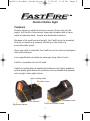
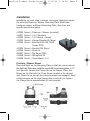
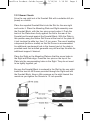
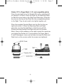
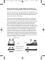
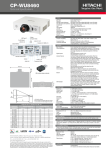
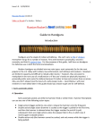
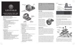
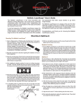
FastFire Product Guide:Layout 1
2/14/08
1:19 PM
Page 1
FastFire Product Guide:Layout 1
2/14/08
1:19 PM
Page 2
Red-Dot Reflex Sight
Features
Smaller, lighter in weight and more compact than most red dot
sights, the FastFire is extremely strong and durable with a frame
made of stainless steel, bronze and anodized aluminum.
Because of its small size and weight, the FastFire can be mounted
directly on almost any weapon including on the slide of a
semi-automatic pistol.
Since eye relief is unlimited, the FastFire can be used on handguns,
rifles and shotguns.
Low magnification provides an extremely large field-of-view.
FastFire is parallax-free to 50 yards.
FastFire’s multicoating is sandwiched between two highly polished,
optical quality glass lenses for protection from scratches and abrasion
and a bright, clear sight picture.
Light-emitting diode
Elevation screw
Lens element
Brightness sensor
Windage screw
Thrust and clamp screws
1
FastFire Product Guide:Layout 1
2/14/08
1:19 PM
Page 3
Operating Instructions
For optimum performance and to prevent damage to this precision
instrument, carefully follow all instructions.
Package Contents:
• 2 #6x48 countersink screws with Torx® socket head for installing
the sight on the mounting plate
• 1 Torx® wrench to tighten fasteners
• 1 screwdriver
• 1 adjusting disc
• 1 protective cap
• 1 3V Lithium battery (CR 2032)
• Operating instructions
• Weaver/Picatinny-style mount
Specifications:
• Magnification: 1.07X
• Sight Window: 21mm x 15mm; .82" x .59"
• Elevation adustment range: 3 degrees or 190 in.@100 yds.
(524cm @100m)
• Windage adjustment range: 3 degrees or 190 in.@ 100 yds.
(524cm @100m)
• Set value for one scale division: 1 MOA or 1 in.@100 yds.with 60
scale divisions per turn
• Subtension of the aiming dot:
4 MOA (10.5cm@100m)
• Parallax-free sighting distance: approx. 50 yards
• Recoil resistance: At least 1000 G’s
• Operating Temperature Range: -10°F to +130°F (-25°C to +55°C)
• Storage Temperature Range: -40°F to +160°F (-40°C to +70°C)
• Power Supply: 3V with one CR 2032 Lithium battery
• Dimensions: (LxWxH) 1.8"x1.0"x0.9" (46mm x 25.4mm x 23.7mm)
• Weight (in operating condition without mounting materials):
0.9 oz. (25 grams)
Torx® is a registered trademark of Camcar/Textron
2
FastFire Product Guide:Layout 1
2/14/08
1:19 PM
Page 4
Cautions and Warnings
Always make certain the chamber of your firearm is empty by
following the “clearing” procedure detailed in your firearm’s operator’s
manual. Do not look directly into the sun, light arcs or other highintensity light sources. Keep away from children.
Remove dirt by blowing it off or use a very soft brush. Use lens
cleaning tissues on the optical surfaces. Do not touch the luminous
dot.
Set-up
Operate with one commercially available 3V Lithium battery (CR
2032) only. Do not attempt to substitute two CR 2016 batteries.
Insert the battery into the receptacle located on
the underside of the housing oriented so that
the positive pole on the battery label is visible.
A magnet draws the battery onto the contact
plate. Keep the contact surface clean, cleaning
with alcohol if necessary.
Battery Replacement
Remove the FastFire and turn it upside down. Place the Allen
wrench or a screwdriver in the notch and pry the battery loose.
Insert a new battery as described
earlier. The precision pins avoid the
need for any readjustment.
Power-saving Mode
To save power, simply turn the
ON/OFF switch to OFF.
3
FastFire Product Guide:Layout 1
2/14/08
1:19 PM
Page 5
Installation
Installation on most rifles, carbines, and some handguns require
the included Picatinny/ Weaver Mounting Plate. Most other
handguns require a different Mounting Plate. See chart and
special instructions below.
410320
410321
410322
410323
410324
Mount
Mount
Mount
Mount
Mount
410325
410326
410327
410328
410329
Mount
Mount
Mount
Mount
Mount
- Picatinny / Weaver (included)
- 1911 Standard
- 1911 Bomar / Novak
- Kimber Standard & Target
- Beretta 92/96 /90-TWO/
Taurus PT99
- Beretta PX4 Storm
- Glock all
- Sig Sauer P226
- Springfield XD
- Ruger Mark I, II, II
Picatinny / Weaver Mount
Place the Sight on the Mounting Plate so that the screw holes in
the Sight and Plate align. Install the two #6-48 Screws and tighten to 12
inch pounds. Loosen the Clamp Nut on the Mount. Place the
Mount on the Rail with the Cross Screw located in the desired
slot. Check to be sure all the clamping edges are engaged. Keep
a little pressure on the sight toward the muzzle as you tighten
the Clamp Nut to approximately 20 inch pounds.
4
FastFire Product Guide:Layout 1
2/14/08
1:19 PM
Page 6
1911 Bomar / Novak
Drive the rear sight out of its Dovetail Slot with a suitable drift pin
(brass) or a fixture.
Place the supplied Dovetail Block into the Slot for the rear sight
and center it. Place the Mounting Plate and Sight assembly over
the Dovetail Block, with the four pins up and center it. Push the
back of the Plate down firmly against the flat to the rear of the
Dovetail and forward against the Dovetail Block. With the Plate in
this position snug the hollow Set Screw at the front of the plate till
it just touches the slide top, then 1/4 turn more. The use of bonding
compound (loctite or similar) on this Set Screw is recommended.
An additional countersunk hole in the forward part of the plate is
provided such that a skilled gunsmith may drill and tap the slide for
additional support if desired.
Place the Sight on the Mounting Plate so that the screw holes in
the Sight and Plate align. Press the four pins on the top of the
Plate into the corresponding holes in the Sight. They do not need
to be tightly together yet.
Be sure the Dovetail Block is centered in the Slot for the rear sight.
Install the two #6-48 Screws provided through the Sight and into
the Dovetail Block. Keep a little pressure on the sight toward the
muzzle as you tighten the Screws to 12 inch pounds.
5
FastFire Product Guide:Layout 1
2/14/08
1:19 PM
Page 7
Kimber 1911s, Ruger Mark I, II, III, and compatible pistols
Drive the rear sight out of its Dovetail Slot with a suitable drift
pin (brass) or a fixture. Place the Sight on the Mounting Plate
so that the screw holes in the Sight and Plate align. Press the
four pins on the top of the Plate into the corresponding holes
in the Sight. They do not need to be tightly together yet.
Place the supplied Dovetail Block into the Slot for the rear
sight and center it. Place the Mounting Plate and Sight
assembly over the Dovetail Block. Install the two #6-48
Screws provided through the Sight and into the Dovetail
Block. Keep a little pressure on the sight toward the muzzle as
you tighten the Screws to 12 inch pounds. On Ruger Mark I,
II, and III handguns, care must be taken to keep the Plate and
Sight level on the receiver while the screws are tightened.
6
FastFire Product Guide:Layout 1
2/14/08
1:19 PM
Page 8
Beretta (92, 96, 90-TWO, Cougar, PX4Storm) Sig P226, 1911
Standard, Glock, Springfield XD, PT99 Taurus, and compatibles.
Drive the rear sight out of its Dovetail Slot with a suitable drift pin
(brass) or a fixture. (Note; Beretta dovetails are tapered wide on the
left, narrower on the right (as well as bottom to top) so drive the
sight out the left side of the slide.)
Place the supplied Dovetail Block into the Slot for the rear sight
and center it. Place the Mounting Plate down over the Dovetail
Block with the countersunk holes lined up with the threaded holes
in the Dovetail Block, countersink up. Loosely install two of the
shorter #6-48 Screws through the Plate and into the Dovetail
Block. Center the Mounting Plate along the slide and tighten the
Screws into the Dovetail Block to 12 inch pounds. On some models
care must be taken to keep the Plate level on the slide while the
screws are tightened. The use of bonding compound (loctite or
similar) on these Screws is recommended. An additional countersunk hole in the forward part of the plate is provided such that a
skilled gunsmith may drill and tap the slide for additional support if
desired. Place the Sight on the Mounting Plate so that the screw
holes in the Sight and Plate align. Install the two long #6-48 Screws
provided and tighten to 12 inch pounds.
7
FastFire Product Guide:Layout 1
2/14/08
1:19 PM
Page 9
Operating Procedure
Elevation and Windage Adjustment
Separate controls for the elevation and
windage adjustments are found on the top
and right side of the sight.
Loosen the two LOCK screws counter clockwise 1/2 turn each using the provided screwdriver. Turn the slotted “UP or LEFT” screws with the provided
adjusting disc and screwdriver. The windage adjustment mechanism
has limit stops at both ends.
Note that the elevation adjustment downward stop is available
only when the unit is installed on a mounting plate. Screwing either
adjustment into a stop will lock motion of the other adjustment.
Zeroing the Point-of-Impact
Adjust point-of-impact by using the provided scale disc with
integrated screwdriver.
Put the scale disc
onto the elevation or
windage adjustment
screws using any
edge on the sight as
the reference line. The
scale disc allows
defined elevation and
windage adjustment in
both directions of
rotation. The direction
of the shift of the
point-of-impact is indicated on the FastFire
sight and on the scale disc.
8
FastFire Product Guide:Layout 1
2/14/08
1:20 PM
Page 10
One scale division of this
disc corresponds to 1
minute of angle (MOA),
very close to 1 inch at 100
yards. For other distances,
this value is proportional.
For example: 1/2 inch at 50
yards or 0.1 inch at 10
yards.
Before shooting, make
sure to tighten the lock
screws on the rear of the
FastFire with the provided
screw driver making sure not to overtighten.
Integrated Control Electronics
The integrated control circuit adjusts the brightness of the aiming
dot according to surrounding light levels.
The brightness sensor on the front of the sight senses the light
level in the direction of the target and modifies the intensity of the
dot accordingly so that it is not overpowering in low light while
remaining highly visible in bright daylight.
Be careful not to obstruct the sensor. Clean if necessary.
Covering the sensor with your finger will affect the electronics
only slightly. If you wish to check its function, cover the sensor
with the protective cover.
To ensure immediate functionality, the light-emitting diode will
remain on even in complete darkness but uses such a small
amount of energy that you can expect a service life of up to 4
years.
9
FastFire Product Guide:Layout 1
2/14/08
1:20 PM
Page 11
Ambient Conditions
Although not completely waterproof, the FastFire is water-resistant
and is usable even when exposed to moisture.
Exposure to such conditions should be limited, however, to
prevent the battery from discharging and to avoid an electrolytic
reaction. After exposure to salty or dirty water, rinse with distilled
water and dry the sight.
LIMITED WARRANTY
BURRIS 12 MONTH LIMITED WARRANTY
Burris warrants for 12 months after purchase that its products
will be free from defects in material and workmanship. At its sole
discretion, Burris will either repair or replace, at no charge, any
product or part (with the exception of the lamp and battery)
which is found to be defective under normal use and service.
Burris’s obligation to either repair or replace shall be the
purchaser’s sole and exclusive remedy under this warranty.
The warranty does not cover battery leakage.
This warranty extends only to the original owner. There are no
warranties, expressed or implied, other than as set forth on this
page and Burris disclaims any warranties of merchantability or
fitness for a particular purpose. Burris shall not be liable for
incidental. consequential, or special damages arising out of or in
connection with product use or performance. For service, repair,
or replacement, return unit “UPS Prepaid” with a copy of the
sales receipt to Burris.
Fastfire™ is a trademark of Burris Company Inc.
10
FastFire Product Guide:Layout 1
2/14/08
1:20 PM
Burris Company
331 East 8th Street, Greeley, CO 80631
Ph: 970-356-1670
Fax: 970-356-8702
www.burrisoptics.com
Page 12