1
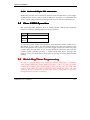
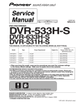
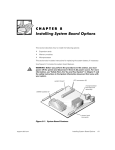
System Installation
CHAPTER 3
System Installation
This chapter provides you with instructions to set up your system. The
additional information is enclosed to help you install M-systems Flash disk and
set up onboard PCI device.
3-1 Socket 370 PentiumPentium-III Processor
Installing S370 CPU
1) Lift the handling lever of CPU socket outwards and upwards to the other end.
2) Align the processor pins with pin holes on the socket. Make sure that the
notched corner or dot mark (pin 1) of the CPU corresponds to the socket’s
bevel end. Then press the CPU gently until it fits into place. If this operation
is not easy or smooth, don’t do it forcibly.
3) Push down the lever to lock processor chip into the socket.
4) Follow the installation guide of cooling fan or heat sink to mount it on CPU
surface and lock it on the socket 370 with a good contact.
5) Do the same for the other CPU if this is required.
Removing CPU
1) Unlock the cooling fan first.
2) Lift the lever of CPU socket outwards and upwards to the other end.
3) Carefully lift up the existing CPU to remove it from the socket.
4) Follow the steps of installing a CPU to change to another one or place
handling bar to re-lock CPU.
5) Do the same for the other CPU if this is required.
Configuring System Bus
ROBO-667 will automatically detect system bus based on the type of CPU used.
CPU speed of Intel PIII can be detected automatically.
ROBO-667 User’s Manual
3-1
System Installation
WARNING
ROBO-667 is designed for high performance applications by dual processors
architecture. Using only single processor may cause unpredictable errors.
Basing on the same reason, Celeron processor is not suitable for ROBO-667
because it does not support dual processors architecture.
3-2 Main Memory
ROBO-667 provides three DIMMs (168-pin Dual In-line Memory Module) to
support 3.3V SDRAM (Synchronized DRAM) as on-board main memory. The
maximum total memory size can be up to 1.5 GB. It also supports ECC &
registered DIMMs.
For system compatibility and stability, memory module without a brand is not
suggested. You can also use the single or double-sided DIMM. Randomly
installing DIMM in any one of the DIMM sockets is allowed. You can install
different size of DRAM module onto DIMM1, DIMM2, DIMM3 or all DIMM
positions to make the system boot.
Watch out the contact and lock integrity of memory module with socket, it will
impact on the system reliability. Follow normal procedures to install your
DRAM module into memory socket. Before locking, make sure that all modules
have been fully inserted into the card slots.
NOTE :
(1) To maintain system stability, don’t change any of DRAM parameters in
BIOS setup to upgrade your system performance without acquiring
technical information.
ROBO-667 User’s Manual
3-2
System Installation
3-3 MM-systems Flash Disk
ROBO-667 reserves one 32-pin DIP sockets for installing M-systems Flash disk
from 2MB to 288MB. This operation structure is running with pure ISA-bus
without PnP (Plug and Play) function. Before installing, make sure that I/O
address jumper setting is set on right position to prevent unworkable system
due to I/O resource conflict. Do remember to follow DOC (DiskOnChip)
installation procedure. Otherwise, it is possible to burn out the Flash chip due to
incorrect installation.
Installing DOC
Align the DOC with pin holes on the socket. Make sure that the notched corner
or dot mark (pin 1) of DOC corresponds to notched corner of the socket. Then
press the DOC gently until it fits into place. If installation procedure is correct,
the Flash disk can be viewed as a normal hard disk to access read/write data.
WARNING
Please ensure that your DOC is properly inserted. Placing the DOC in
reverse will cause severe damage. Remember, a new DOC chip is always
a formatted disk. You may simply plug the chip on the DOC socket and
read/write through it. If you would like to boot from this Flash disk, it is
necessary to refer to the application note from M-systems. You can easily
get relative information from M-systems shipping package (such as
product manual) or Web-site
http://www.m-sys.com.
ROBO-667 User’s Manual
3-3
System Installation
3-4 Installing the Single Board Computer
To install your ROBO-667 into standard chassis or proprietary environment,
you need to perform the following:
Step 1 : Check all jumpers setting on proper position
Step 2 : Install and configure CPU and memory module on right position
Step 3 : Place ROBO-667 into the dedicated position in your system
Step 4 : Attach cables to existing peripheral devices and secure it
WARNING
Please ensure that your SBC is properly inserted and fixed by mechanism.
Otherwise, the system might be unstable or do not work due to bad contact of
golden finger and ISA-bus slot. It is recommended to apply 4-pin 5-1/4” IDE
device power connectors from your power supply onto J11 & J12 to ensure a
sufficient current supply.
NOTE : Please refer to section 3-4-1 to 3-4-3 to install 4 IN 1/VGA/LAN drivers.
3-4-1 Chipset Component Driver
The chipset on ROBO-667 is a new chipset that a few old operating systems
might not be able to recognize. To overcome this compatibility issue, for
Windows Operating Systems such as Windows-95/98/98SE/2000, please install
VIA 4-in-1 driver before any of other Drivers are installed. You can find very
easily this chipset component driver in ROBO-667 CD-title.
ROBO-667 User’s Manual
3-4
System Installation
3-4-2 ATI RageRage-Mobility M/M1 VGA Chip
Chip
ROBO-667 CD-title also include ATI VGA drivers of Microsoft windows series.
Since M/M1 needs DirectX (version 7 at least) to enable 3D function, please
install Direct X contained in CD when installing WIN95/98/98SE. Windows
2000 has contained DirectX 7 and Windows XP has contained DirectX 8.1, so
they don’t need to install DirectX.
3-4-3 Intel 82559 Fast Ethernet Controller
Please find 82559 LAN driver in /Ethernet directory of ROBO-667 CD-title. The
drivers support Windows-NT 3.51/4.0, Windows-95/98/98SE, Windows-2000,
SCO OpenServer 5.0.2, SCO Unixware 7.0, OS2 and Linux.
In Windows environment, Intel 82559 Fast Ethernet should appear as Intel (R)
PRO/100 VE Network Connection.
On-board LED Indicator (for LAN status)
ROBO-667 provides three LED indicators to report 82559 Fast Ethernet
interfaces status. Please refer to the table below as a quick reference guide.
Intel
82559
Name of LED
Operation of Ethernet Port
ON
Off
LED1
LAN Link Integrity LED
Good link in 10 or 100 Mbps Bad link
LED2
LAN speed LED
100 Mbps
10 Mbps
LED3
LAN active LED
Active
No active
ROBO-667 User’s Manual
3-5
System Installation
3-4-4 OnOn-board 6868-pin PCI connector
ROBO-667 provides one on-board 68-pin PCI connector that allows you to apply
additional PCI devices, such as SCSI or Ethernet. If you have a compatible PCI
device, simply plug it onto the connector and secure it with two retention bars.
3-5 Clear CMOS Operation
The following table indicates how to enable/disable CMOS Clear Function
hardware circuit by putting jumpers at proper position.
JP2
1-2
Short
2-3
Short
FUNCTION
Normal Operation
Clear CMOS Contents
To correctly operate CMOS Clear function, users must turn off the system, move
JP2 jumper to 2-3 position. To clear CMOS, please turn the power back on and
turn it off again for AT system, or press the toggle switch a few times for ATX
system. Move the JP2 back to 1-2 position (Normal Operation) and start the
system. System will then produce a “CMOS Check Sum Error” message and
hold up. Users may then follow the displayed message to load in BIOS default
setting.
3-6 Watch Dog Timer Programming
It’s easy to program Watch Dog Timer by softwere language(ex. Assembly).
After enable Watch Dog Timer hardware jumper ( JP6 1-2 ) and set proper
enabled ISA location ( ISA address 533h or 543h ,by JP6 3-4 ), Just read “ISA
address 533h/543h” by software language, then watch dog timer will start
counting. It can be disable by reading “ISA address 033h/343h” at any time,
though Watch Dog Timer is counting!
ROBO-667 User’s Manual
3-6