1
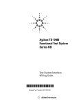
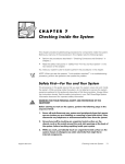
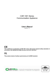
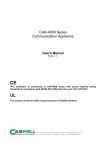
CHAPTER 8
Installing System Board Options
This section describes how to install the following options:
•
•
•
Expansion cards
Memory modules
Microprocessor
This section also includes instructions for replacing the system battery, if necessary.
Use Figure 8-1 to locate the system board features.
WARNING: Before you perform the procedures in this section, you must
power off the system and disconnect it from its AC power source. For more
information, see “Safety First—For You and Your System” in Chapter 7 and
the safety instructions in the System Information document that came with
your system.
system board
PCI connectors (2)
microprocessor
and heat sink
assembly
DIMM sockets (4)
power input
connector
Figure 8-1. System Board Features
support.dell.com
Installing System Board Options
8-1
Expansion Cards
Expansion cards are installed on the system’s riser board or the system board right
angle connector. The riser board plugs into the PCI2 connector on the system board
(see Figure 8-1) and is considered an extension of the system board.
The system board supports two 32-bit, 33-megahertz (MHz), peripheral component
interconnect (PCI) expansion-card connectors. The low-profile PCI slot is occupied by
the system’s video controller card and only the full-length PCI slot is available for an
expansion NIC card.
Removing an Expansion Card
To remove an expansion card, perform the following steps.
CAUTION: Observe the precautions in “Safety First—For You and Your
System” in Chapter 7 and the safety instructions in the System Information
document that came with your system.
NOTICE: See “Protecting Against Electrostatic Discharge” in the safety
instructions in your System Information document.
1.
Remove the cover.
2.
Remove the two screws securing the PCI retention panel to the chassis back
panel (see Figure 8-2).
screws (2)
PCI retention panel
Figure 8-2. PCI Retention Panel Removal
8-2
Installation and Troubleshooting Guide
3.
Disconnect any cables connected to expansion cards through the back-panel
openings.
4.
Disconnect any internal cables connected to expansion cards.
5.
Remove the riser board, together with installed expansion cards, from the
system board.
6.
Remove the expansion card from its slot on the riser board (see Figure 8-3).
7.
If you are removing the card permanently, install a metal filler bracket over the
empty card-slot opening.
NOTE: Installing a filler bracket over an empty expansion slot is necessary to maintain
Federal Communications Commission (FCC) certification of the system. The brackets
also keep dust and dirt out of the system and aid in proper cooling and airflow inside
the system.
8.
Replace the cover, and then reconnect the system and peripherals to their AC
power sources and power them on.
expansion cards (2)
(low-profile PCI slot contains
video controller)
riser board
riser board sockets
J20 (left) and J13
(right)
Figure 8-3. Expansion Card Removal
support.dell.com
Installing System Board Options
8-3
Installing an Expansion Card
To install an expansion card, perform the following steps.
CAUTION: Observe the precautions in “Safety First—For You and Your
System” in Chapter 7 and the safety instructions in the System Information
document that came with your system.
NOTICE: See “Protecting Against Electrostatic Discharge” in the safety
instructions in your System Information document.
1.
Remove the system cover, if it is not already removed.
2.
Prepare the replacement expansion card for installation.
See the documentation that came with the expansion card for information on
configuring the card, making internal connections, or otherwise customizing the
card for the system.
3.
To remove a PCI retention panel (if it is not already removed), remove the two
screws securing it to the chassis back panel (see Figure 8-2).
4.
Remove the riser board, together with installed expansion cards, from the
system board. See “Removing and Replacing the Riser Board” in this chapter.
5.
To install the replacement expansion card, insert the card-edge connector firmly
into the socket on the riser board.
6.
Connect any cables that should be attached to the card.
See the documentation that came with the card for information about cable
connections.
7.
Install the riser board into the chassis. See “Removing and Replacing the Riser
Board” in this chapter.
8.
To replace a PCI retention panel, position the tab on the end into its slot and
install two screws to secure it to the chassis back panel (see Figure 8-2).
9.
Replace the cover, and then reconnect the system and peripherals to their AC
power sources and power them on.
Removing and Replacing the Riser Board
To remove the expansion card riser board, perform the following steps:
CAUTION: Observe the precautions in “Safety First—For You and Your
System” in Chapter 7. Also observe the safety instructions in your System
Information document.
1.
8-4
Remove the system cover if it is not already removed.
Installation and Troubleshooting Guide
Figure 8-4. Riser Board Removal
2.
Grasp the riser firmly and lift it up and out of the chassis (see Figure 8-4).
3.
Disconnect any cables connected to the expansion cards.
4.
Remove the expansion cards installed on the riser board.
Memory Modules
The system is upgradable to 1 GB by installing combinations of 128, 256, and 512 MB
ECC unbuffered SDRAM memory modules. You can purchase memory upgrade kits
from Dell as needed. See Figure 8-1 to locate the DIMM sockets.
CAUTION: Observe the precautions in “Safety First—For You and Your
System” in Chapter 7 and the safety instructions in the System Information
document that came with your system.
NOTICE: See “Protecting Against Electrostatic Discharge” in the safety
instructions in your System Information document.
Memory Module Installation Guidelines
Starting with the socket nearest to the system board's center, the DIMM sockets are
labeled “DIMM3” through “DIMM0” (see Figure 8-5). When you install memory
modules, follow these guidelines:
•
Install a DIMM in socket DIMM3 (the socket toward the center of the board)
before socket DIMM2, socket DIMM2 before socket DIMM1, and so on.
The reason for installing memory in the back-most socket first is for ease of
future installations.
support.dell.com
Installing System Board Options
8-5
•
•
If you install different sizes of memory modules, install them in order of
descending capacity, beginning with the highest-capacity DIMM in socket
DIMM3.
You do not need to install memory modules in pairs.
DIMM3
DIMM0
Figure 8-5. DIMM Sockets
Table 8-1 illustrates the valid memory configurations based on these guidelines.
Table 8-1. Sample DIMM Configurations
8-6
DIMM Sockets
Total Desired
Memory
DIMM3
DIMM2
DIMM1
DIMM0
128 MB
128 MB
none
none
none
256 MB
256 MB
none
none
none
512 MB
256 MB
256 MB
none
none
1 GB
256 MB
256 MB
256 MB
256 MB
Installation and Troubleshooting Guide
Memory Installation and Replacement
To install or replace a memory module on the system board, perform the following
steps.
CAUTION: Observe the precautions in “Safety First—For You and Your
System” in Chapter 7 and the safety instructions in the System Information
document that came with your system.
NOTICE: See “Protecting Against Electrostatic Discharge” in the safety
instructions in your System Information document.
1.
Power off the system, including any attached peripherals, and disconnect the AC
power cable from its power source.
2.
Remove the front bezel, if one is present.
3.
Remove the cover.
4.
Locate the DIMM socket(s) in which you will replace memory modules.
Figure 8-5 shows the location and labeling of the DIMM sockets on the system
board.
5.
Replace the memory modules as necessary to reach the desired memory total.
When installing a memory module in DIMM3, perform the following steps:
support.dell.com
1.
Press down and outward on the right-hand ejector (the one nearest the
microprocessor/heat-sink assembly). The DIMM socket has two alignment keys
that allow the DIMM to be installed in the socket only one way.
2.
Press the right-hand corner of the module into the DIMM3 socket
(see Figure 8-6).
3.
Holding the right-hand corner of the module in place, press down and outward on
the left-hand ejector and rotate the left-hand side of the module into position.
4.
After you are sure that the module is centered in the socket, press down on the
DIMM while pulling up on the ejectors to lock the DIMM into the socket (see
Figure 8-7).
Installing System Board Options
8-7
Figure 8-6. DIMM3 Installation
After DIMM3 has been installed, install the remaining memory modules using the
following procedure:
1.
Press down and outward on the ejectors on the DIMM socket to allow the DIMM
to be inserted into the socket. (See Figure 8-7).
2.
Align the DIMM's edge connector with the slot in the center of the DIMM
socket, and insert the DIMM in the socket (see Figure 8-7).
The DIMM socket has two alignment keys that allow the DIMM to be installed in
the socket in only one way.
3.
Press down on the DIMM with your thumbs while pulling up on the ejectors with
your index fingers to lock the DIMM into the socket (see Figure 8-7).
4.
When all of the DIMMs are properly seated in the sockets and the ejectors are in
the locked position, verify that all of the DIMMs and all of the ejectors are in
alignment with one another. Reseat any modules that appear to be out of
alignment.
5.
Replace the cover, replace the optional front bezel (if one is present), and
reconnect the system to the electrical outlet, and power on the system.
After the system completes the POST routine, it runs a memory test that
displays the new memory total, which includes all newly installed memory.
NOTE: If the memory total is incorrect, power off and disconnect the system and
peripherals from their AC power sources, open the system cover, and check all the
installed memory modules to make sure they are seated properly in their sockets.
Ensure that the installed memory modules conform to one of the valid configurations
listed in Table 8-1.
6.
8-8
Press <F2> to enter the System Setup program and check the System Memory
setting in the system data box on the System Setup screens. The system should
have already changed the value in the System Memory setting to reflect the
newly installed memory.
Installation and Troubleshooting Guide
7.
If the System Memory value is incorrect, one or more of the memory modules
may not be installed properly. Repeat steps 1 through 6.
Carefully examine each DIMM to ensure proper seating in its socket.
8.
Run the system memory test in the Dell Diagnostics (see Chapter 5, “Running
the Dell Diagnostics” for complete information).
DIMM socket
ejectors (2)
alignment keys (2)
Figure 8-7. DIMM Installation
Memory Module Removal
To remove a memory module, press down and outward on the ejectors on each end
of the socket until the memory module pops out of the socket (see Figure 8-8).
CAUTION: Observe the precautions in “Safety First—For You and Your
System” in Chapter 7 and the safety instructions in the System Information
document that came with your system.
NOTICE: See “Protecting Against Electrostatic Discharge” in the safety
instructions in your System Information document.
NOTES: This procedure assumes the power is off and you have access to the DIMM
slots. See steps 1 through 6 in “Memory Installation and Replacement” for these
preliminary steps.
If you encounter difficulty in moving the ejector nearest to the chassis wall, press
down on the opposite ejector and lift that end of the DIMM slightly to free the DIMM
from its socket.
support.dell.com
Installing System Board Options
8-9
DIMM socket ejectors (2)
Figure 8-8. DIMM Removal
Replacing the Microprocessor
The microprocessor and heat sink assembly is secured to the system board in a zeroinsertion-force (ZIF) socket.
To remove the microprocessor and heat sink assembly, perform the following steps.
CAUTION: Observe the precautions in “Safety First—For You and Your
System” in Chapter 7 and the safety instructions in the System Information
document that came with your system.
NOTICE: See “Protecting Against Electrostatic Discharge” in the safety
instructions in your System Information document.
Removing the Microprocessor and Heat Sink
To remove the microprocessor and heat sink, perform the following steps.
CAUTION: The microprocessor and heat sink assembly can get extremely
hot during system operation. Be sure the assembly has had sufficient time
to cool before you touch it.
CAUTION: When handling the microprocessor and heat sink assembly, take
care to avoid sharp edges on the heat sink.
8-10
1.
Power off the system, including any attached peripherals, and disconnect the AC
power cable from its power source.
2.
Remove the front bezel.
3.
Remove the system cover.
4.
Disconnect the AC power cable and all peripheral cables from the back panel of
the system.
Installation and Troubleshooting Guide
5.
Release the clip securing the heat sink to the microprocessor socket by first
inserting a small flat-tip screwdriver into the upper slot at the front of the socket
to release the clamp, and then releasing the clip from the opposite side of the
socket.
6.
Grasp the end of the ZIF socket arm and bend it out slightly until it disengages
from the socket tab.
7.
Swing the ZIF arm up to the upright position.
The microprocessor and heat sink assembly are now unlocked from the ZIF
socket.
NOTICE: The microprocessor may adhere to the heat sink assembly
because of a layer of thermal grease applied to the top of the
microprocessor. When lifting the heat sink away, use care to prevent the
microprocessor from separating from the heat sink and falling on system
board components.
8.
Lift the microprocessor and heat sink assembly away from the ZIF socket (see
Figure 8-9).
heat sink clip
microprocessor and heat
sink assembly
microprocessor
ZIF socket
ZIF socket
release lever
tab on ZIF socket (2)
Figure 8-9. Microprocessor and Heat Sink Removal
support.dell.com
Installing System Board Options
8-11
Microprocessor and Heat Sink Assembly Replacement
To install the replacement microprocessor and heat sink assembly, see Figure 8-10
and perform the following steps:
1.
Remove the microprocessor and heat sink assembly.
2.
Gently place the replacement microprocessor into the ZIF socket so that the
processor pins mate exactly with the ZIF socket.
Make certain that pin 1 of the microprocessor is oriented correctly in the socket.
CAUTION: Do not force the processor into the socket. Even slight pressure
can bend the microprocessor pins.
3.
With the microprocessor in place, swing the ZIF socket arm down until it snaps
into the socket tab (see Figure 8-10).
heat sink clip
heat sink
microprocessor
ZIF socket
ZIF socket
release lever
tab on ZIF socket (2)
Figure 8-10. Microprocessor and Heat Sink Replacement
4.
8-12
At the base of the heat sink, remove and discard any protective cover that may be
over the thermal grease by pulling on the cover's tab.
Installation and Troubleshooting Guide
5.
Carefully place the heat sink on the microprocessor.
Be careful not to touch the surfaces coated with thermal grease. The beveled
surface on the heat sink covers the part of the ZIF socket that is not covered by
the microprocessor.
6.
Drop the heat sink clip into the heat sink's center groove, with the end of the clip
that has two slots facing the front of the ZIF socket.
7.
Gently hold the heat sink in place as you press down on the end of the shorter
end of the heat sink clip (the end that has a single slot) until that end snaps into
its tab on the back of the ZIF socket.
8.
Use your thumb to press down on the front end of the heat sink clip (the end that
has two slots) until it snaps into the socket tab.
9.
Replace the system cover, install the power cord, and power on the system.
Replacing the Battery
The system battery maintains system configuration, date, and time information in a
special section of memory when you power off the system. The operating life of the
battery ranges from 2 to 5 years, depending on how you use the system (for example,
if you keep the system on most of the time, the battery gets little use and thus lasts
longer). You may need to replace the battery if an incorrect time or date is displayed
during the boot routine along with the following or similar message:
Time-of-day not set -- please run SETUP program
Strike the F1 key to continue, F2 to run the setup utility
or
System CMOS checksum bad -- Run SETUP
Strike the F1 key to continue, F2 to run the setup utility
or
Invalid configuration information -- please run SETUP program
Strike the F1 key to continue, F2 to run the setup utility
To determine if the battery needs replacing, reenter the time and date through the
System Setup program. Power off and disconnect the system from the electrical
outlet for a few hours, and then reconnect and power the system on again. Enter the
System Setup program. If the date and time are not correct in the System Setup
program, replace the battery.
NOTES: Some software may cause the system time to speed up or slow down. If the
system seems to operate normally except for the time kept in the System Setup
program, the problem may be caused by software rather than by a defective battery.
If the system is turned off for long periods of time (for weeks or months), the NVRAM
may lose its system configuration information. This situation is not caused by a
defective battery.
support.dell.com
Installing System Board Options
8-13
You can operate the system without a battery; however, the system configuration
information maintained by the battery in NVRAM is erased each time you shut down
the system. Therefore, you must reenter the system configuration information and
reset the options each time the system boots until you replace the battery.
The battery is a 3.0-volt (V), coin-cell CR2032-type battery. To remove the battery,
perform the following steps.
CAUTION: Observe the precautions in “Safety First—For You and Your
System” in Chapter 7 and the safety instructions in the System Information
document that came with your system.
CAUTION: There is a danger of a new battery exploding if it is incorrectly
installed. Replace the battery only with the same or equivalent type
recommended by the manufacturer. Discard used batteries according to the
manufacturer’s instructions.
1.
Enter the System Setup program and, if possible, make a printed copy of the
System Setup screens.
See “Using the System Setup Program,” in the User's Guide for instructions.
2.
Shut down the system, including any attached peripherals, and disconnect the
system from the electrical outlet.
3.
Open the system cover.
4.
Remove the battery.
Pry the battery out of its socket with your fingers or with a blunt, nonconductive
object such as a plastic screwdriver.
5.
Install the new battery with the side labeled “+” facing up (see Figure 8-11).
Figure 8-11. Installing the Battery
8-14
Installation and Troubleshooting Guide
6.
Close the system cover, and then reconnect the system and peripherals to their
AC power sources and power them on.
7.
Enter the System Setup program to confirm that the battery is operating properly.
8.
Enter the correct time and date through the System Setup program's time and
date settings. Also reenter any system configuration information that is no longer
displayed on the System Setup screens, and then exit the System Setup
program.
9.
To test the newly installed battery, power off and disconnect the system from the
electrical outlet for at least an hour.
10. After an hour, plug in and power on the system and enter the System Setup
program. If the time and date are still incorrect, see Chapter 10, “Getting Help,”
for instructions on obtaining technical assistance.
support.dell.com
Installing System Board Options
8-15
8-16
Installation and Troubleshooting Guide