1
Leica Microsystems- the brand
for outstanding J•ro{lticts
Leica Microsystems' Mission is to be th e world's fi rst-chotco pt OvHii n nl IIIIHtvll tt vn
solutions to our customers' needs for vision, mea surement, lillio\l lltpli y 1111rl llt n ol yii t ~
of micro structure s.
Leica, th e lead ing brand for microscope s and sc ientifi c tn strum ont s, 11 11 ; il uvulupuil
from five brand names, al l wi th a long tradition : Wild, Lott 7, Rotcli ot 1..Jnnu 11 11!1
Camb ridg e Instruments. Leica symbolizes not only tradition, but also tnnuvllllllll
lli1 1 GUIIIP III IIO S
"'ttiP• tt HIIri, wht!IH wu 111nk wl tll tll o ru nrku t
lullt hll fii
\1111 11 ... , ,\
Utu IIICjJIIIIhlll lll 11111 fliNt HI/V hi !hi! htt l'hi iOr nil
Utlt NUIII I HIII N
Lt•it·a Mit'I'OS~ sll•ms- an inll·rnational t'OIIIJI<III~
\\ ith a s tron ~ IW!wm·k of cnstonH·r scn in·s
Australia :
Au stria :
Canada :
China :
Denmark:
France:
Gladesville, NSW
Vienna
Richmond Hii i!Ontario
Hong Kong
Herlev
Ru eii-Malmaison
Cedex
Bensheim
Milan
Tokyo
Seoul
Rij swijk
Lisbon
Germany:
Italy:
Japan:
Korea:
Netherlands:
Portug al:
Singapore:
Spain:
Barcelona
Sweden:
Sollentuna
Switzerland:
Glattb rug g
United Kingdom: Milton Keynes
USA:
Bannoc kb urn/ 11 1in ois
Tel.
Tel.
Tel.
Tel.
Tel.
Tel.
Tel.
Tel.
Tel.
Tel.
Tel.
Tel.
Tel.
Tel.
Te l.
Tel.
Tel.
Tel.
+ 1 800 625 286
+43 1 486 80 50 0
+1 905 762 20 00
t8522 564 6699
+45 44 5401 01
Fa x
Fax
Fax
Fax
Fax
+6 1 2 9817 8358
+43 1 486 80 50 30
+ 1 905 762 89 37
+8522 564 4163
+45 44 540 1 11
+33 1 4732 8585
Fax +33 1 4732 8586
+49 6251 1360
Fax +496251 136155
+39 02 57 486 1
Fax +39 02 5740 3273
t 81 3 543 596 09
Fax +81 3 543 596 15
+82 2 514 6543
Fax +82 2 514 6548
+31 70 41 32130
Fax +31 70 41 32 109
+351 213 889112 Fa x +35 1 213 854 668
+65 6 77 97 823
Fax +65 6 77 30 628
+34 93 494 9530
Fa x +34 93 494 9532
+46 8 625 45 45
Fax +46 8 625 45 10
+41 1 809 34 34
Fax +41 1 809 34 44
t 44 1908 666 663 Fax +44 1908 609 992
+ 1 800 248 01 23
Fax + 1 847 405 01 64
of tll U I 011:11 MI CI OSV SIUII IH
fl 1!J III! IIJIU I /1111 11 11111 II(IIIUIIflll y Ill li VU IHI SIII UNN
fur VhllllllitUfiOU , IIIU II!i i/IU III UIII
Olld flllll lyNtS Uf 11\l t; I IINIIII \,II IIIIH hi hill Ill lll1HlU8
I
~
and UHIU SIIy,
"p• ••·un• ·n
~
l•n ·j•arilllull
We specialize in supplying co rn ploltl !:o Oiu t10 ns
Leica M Ster(•o-
for histology and cytopathology.
•
I nw~in;! s, "'''"' ~
With con focal la ser tecll nulouv 01111 1111000
analysis system s, we prov1d e tl11 uo rtun ons1onol
viewing facilitie s and off er now so lut1ons for
cytogenetics, pathol ogy and matorr ul sc1uncos
\ll'dil'al
microscO})(~s
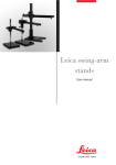
User Manual
l ·. quipll~<'lll
Innova tive tec hnologies in ow S\II {II Cil lrru c iO
scopes offer new th erapeultc npfHOIH'IIoa In
microsurgery. With au tonwtod urstrrmruut lf lot
ophtha lmology, we enn blu ruJw
methods to be ap pliod
fllnunon ll
~t'lllil'llllllll f' lnr l t )llljHII! Ill
Our
au tonHJ tod, luo dln(l
tHIUtl
lllilll lt ll lt llllll tll
an d inspoc !IOII NYNit JI II II 111 111 1101 I hO Ill
lithography sysiO tnMnurku 11• th lt lh1111 rtwlo u
and repn•sp ntaliH ·s of Lt•iea MitTosy;;tems
su pph or tor su mH:OrHhll l\11
in m on· than 100 I'O lllll rit•s.
over th o wur ltl
mnnulm iiiiiiiJ' 1111
The Business Units in Leica Microsystems hold the ma nagement system certificate s
for the internationa l standards ISO 9001 and ISO 14001 relating to quality management,
quality assurance and environmental management.
Leica Microsystems !Switzerland) Ltd
Telephone +41 71 726 33 33
Business Unit SM
Fax +41 71 726 33 99
CH -9435 Heerbrugg
www.leica-microsystems.com
www.stere omicroscopy.com
MI CilU S V IIM
MICROSYS TEMS
D•·ar User
Thank you for choosing our products. We hope that you will enjoy the quality and performance of Leica Microsystems products.
In developing our instruments, we have placed great emphasis
on simp le, self-explanatory directions. In order to utilize all the
benefits of your new stereomicroscope, we suggest studying
this user manua l in detail. Should you have any questions, please
consult your local Leica representative. You will find the address
of the closest local representative as well as valuable information about products and services from Leica Microsystems on
our homepage at www.leica-microsystems.com
We are gladly at your service. Customer service is a big thing
with us. Not only before the sale, but afterwards as well.
Leica Microsystems (Switzerland) Ltd
Business unit Stereomicroscopy
www.stereomicroscopy.com
User Manual
Your instrument is accompanied by a printed English user manual. Additional language versions and information can be found
on the interactive CD-ROM. User manuals and updates are
available for download on our homepage at
www.stereomicroscopy.com .
This user manual contains an explanation of the safety regulations, assembly, handling and accessories of the Leica MS5,
MZ6, MZ75, MZ9s, MZ12s, MZ16 and MZ16 A (if identical) stereomicroscopes. The special functions of the automated stereomicroscope Leica MZ16 A can be found in the separate user
manual M2-116-0.
Leica M Stereomicroscopes User Manual
3
Table of eontents
Page
Overview
Safety concept ........... . .. . .... . . ... . .. .. . .. ... . .. .. . . l:i
Symbols ............ .. . .. .. . . .. . . . . .... . ...... . ... ...... 9
Controls and functions .. .. . . . . .... ... ... . . .... . .. .. . . . .. 10
Use
Changing the magnification ........ .... .. . .. ........ .. ... 12
Ergonomics . . ... ....... .. . ...... .. .... ... .... .. .. . .. ... 14
Interpupill ary distance ........ . . . . ..... .. ..... . ... . . . ... 15
Eye point . . .. . . . . . ........ . .... .. . . . . .. . . .... . . . . . . ... . 15
Eye contact, eyec ups . ..... . ..... . .. . .. .. .. . ... ... . . .. . . 16
Focusing . . ....... . ......... .... . .... . .............. . .. 16
Microscope carrier: Stereoscopic and axial observation . .. . 18
Diopte r settings ............ . ... . .. .. . . ........ . ........ 20
Assembly
Overview: Components .. .. . . .. ..... . . .. . ... .. .. . . .. . . . .. 22
Stand
Profile column for incident light and transmitted-light stands .. 23
Transmitted-l ight stand, bright fie ld, 20 W . . ... . ..... . . ..... 24
Transmitted-l ight stand, bright and dark field ... .... . . . . . ... 26
Transmitted-l ight stand HL .................. .. . . ..... .. .. 27
Swinging-arm stand ESD ... . .. .. ... . ... . . . .. .. . . . . . ..... 28
Large swinging-arm and table-c lamp stands ... . .. . .. ...... 30
Optics carrier, optical accessories
Spacer rings, objective combinations . . ... .... . .. . .. . . ... . 32
Microscope carrier ... . . . . ... .. . .. . .. . .... . . . .... . . .... . 34
Optics carrier ... . . . . . ....... . .. . ........ . ...... . ... . .. . 34
Binocular t ubes, optical accessories ..... . . . .. . .... ... .... 35
Objective no sepie ce (MZ16 and MZ16 A) . . . . . . .. ... . .. .... 36
4
Le ica M Stereomicroscopes User Manu al
Illuminators
Transformers .... . .. . . .... .... .. ...... .. . .. .... . . . ...... 38
Incident lamp 6 V/10 W .... .. . . .... ... .. ...... ...... . ... . 40
Incident lamp 6 V/20 W . . . ..... . .. .. ... . .. .. .... .... .. . . . 42
Cold light sources .... . ... . ........ . .......... . .... . . .. . 45
Fiber-optic light guide . . . . ... . .... . .. . .. .. . ..... . . . ..... .46
LED illumination .. . . . ..... .. ...... .... ...... . . ... . . ... .. 46
Supply (line) lamp 25 W . .. . .. . . .. ..... ... ... . .. ...... . .. 47
Coaxial ill uminator . . . .. ... . .... . ..... . .... . .. .. ....... . . 47
Near-vertical illuminator ... .. . . . . ...... . . . .. . . . . .. .. ... . . 48
Accessories
Fitting accessory tubes ... .. . ....... . . . . . .. .. .. . .... ... . . 50
Double-iris diaphragm .... .. .. . . .... .. . ..... ... . .. ..... . 50
Drawing tube, discussion tube . . . . . . .... ... . . ......... . . . 51
Video/phototubes:
Photography, video, TV, filming, digital imaging . .. . . . .... ... 52
Attachment fo r vertical and oblique observation ..... . .... .. 56
Graticules ............. . . . ......... ... .......... . .... .. 56
Stages, polarization . . ...... .. .. .... .. .. .. ... . . . . . . ... . . . 57
Special notes
Tips and hints: What to do if .. . . ...... . ....... .. ....... . .. 58
Care and maintenance ... . . . ... . ........ . . . . . .. ...... . .. 59
Calculating total magnification and field
of view diameter . . . .. . . . . ........... . .... . . .. .. .... . . .. 61
Optical data for MS5, MZ6 . . . . . . .. ... . . ...... . .. . . . ... . .. 62
Optical data for MZ75, MZ95 . . . . .. ... ..... ... .. .... .. . . .. 64
Optical data for MZ125, MZ16, MZ16 A . . . .. . . . ... . ...... . . 66
Dimensions .. . .. . .. .. . ............. .. . ....... . . . .. ..... 67
Leica M Ste reomicroscopes User Manual
5
Safety rf'g;ulations
General directions
Permitted uses
Prohibited
uses
Read the user manual and safety instructions before starting up.
Workpl aces with stereomicroscopes facilitate and improve the
viewing task, but they also impose high demands on the eyes
and holding muscles of the user. Dependent upon the duration
of uninterrupted activity, this may lead to asthenic t rouble and
muscular-skeletal pain so that suitable measures must be taken
to reduce the strain :
The Leica MS5, MZ6, MZ7s, MZ9s, MZ12s. MZ16 and MZ16 A stereomi cro scopes are optical instruments which use magnification for improved
visua lizati on of objects, their details and specimen s from technology and
natural sciences. The basic outfit, which inc lude s a stand and a light
source, can be supplemented w ith various modules for photography, TV,
dual station viewin g and other applications.
- perfect design of workplace (see p.14). work content and
work process (frequently changing activities).
- detailed introduction of the personnel while considering
ergonomic and organizational work-related aspects.
• The use of the instrument in a different manner from that de sc ribed in
this user manual can lead to injury, malfunction and damage .
• The Leica MS5, MZ6, MZ7s, MZ9s, MZ12s, MZ16 and MZ16 A stereomicroscopes must not be used for eye examinations and operations.
• Do not fit different plugs. Do not dismantle optical systems or mechani cal parts unless instructions for doing so are given in the user manual.
Place
of use
• The Leica MS5, MZ6, MZ7s, MZ9s, MZ12s. MZ16 and MZ16 A stereomicroscopes are intended ma inly for indoor use .
• If the stereomicroscope is used outdoors, protect it from dirt and moisture. Lamps and electrically-operated stands from Leica may not be
used outdoors.
Use in ESD
protected rooms
The optics carriers MS5, MZ6, MZ7s, MZ9s, MZ12s, MZ16 and MZ16 A, the
binocula r tube, Ergo Tube™, ErgoWedge™ 5°-25°, the swinging-arm
stand ESD and the cold light sources Leica L2 and CLS consist of ESDdischarging material (surface resistance <10" ohms/squared, discharge
t1me <2 seconds, 1,000 V to 100 V).
The ergonomic optics concept and the design ofthe Leica M
series aim at limiting the strain on the user to the lowest possible level.
Direct contact with eyepieces can be a potenti al transmission
path for bacterial and viral infections of the eye. Users should
be made aware of the potential risk of infection . The risk can be
kept at a minimum by using individ ua l eyepieces or attachable
eyecups (see p.16).
Electrically-operated items
The safety regulations listed below apply to the following items:
- Transmitted-light stand, bright field, 20 W (page 24)
- Supply (line) lamp 25 W (page 47)
- Regulating transformer 0- 7 V/40 W (page 38)
- Step transformer 4/ 5/6 V (page 39)
- Motor focus (separate instructions)
- Motorized Leica MZ16 A
- A connection socket for a 0 4 mm grounding cable is provided on the
microscope carrier.
- There are two connection sockets for 0 4 mm grounding cables in the
base of the swinging-arm stand .
Servicing
Responsibilities
of person in charge
of instrument
6
Repairs may on ly be carried out by Leica-trained service technicians.
Only original Leica spare parts may be used.
• Ensure that personnel who use the instrument have read and understood this user manual and in particular the safety instructions.
• Ensure thatthe Leica MS5, MZ6, MZ7s, MZ9s, MZ12s, MZ16 and MZ16 A
stereomicroscopes are operated, maintained and repaired on ly by
authorized and tra ined personnel.
Leica M Stereomicroscopes - Safety concept
Liquids
Be careful when handling liquids.
If spilt on the equipment, they can :
- cause the stereomicroscopes and accessories to become
electrically live, endangering personnel,
- cause damage to the equipment.
Power cables
Inspect cables regularly for damage. Defective cables can:
- directly endanger personnel,
- cause the stereomicroscopes and accessories to become
electrically live, endangering personnel.
Leica M Stereomicroscopes - Safety regulations
7
Cable routing
Opening the instrument
Supply voltage
Connections
Changing bulbs
Only authorized Leica personnel are permitted to repair electrical equipment. Before opening up the equipment, pu ll out the
power cable. If you touch the live interior of the equipment, you
may receive an electric shock.
Ensure that the voltage setting on the equipment is correct.
A wrong setting can cause damage to the equipment.
When connecting power-consuming devices to the transformers, do not exceed the maximum permitted loading, as this can
cause damage to the equipment.
• Before changing a bulb, disconnectthe power cable.
• Never attempt to touch the inside of a lamp housing or
transmitted-light stand while the instrument is connected
to the power supply.
• Before changing a bulb, wait until it is cool, otherwise you
may burn your fingers.
Integration in
third-party products
The following must be observed if Leica products are build into
third -party products:
The manufacturer of the complete system or the person putting
it on the market is responsible for adhering to applicable safety
regulations, laws and guidelines.
legal requirements
Adhere to general and local regulations relating to accident
prevention and environmental protection.
Disposal
The products described here must be disposed off in accordance with applicable local laws and regulations.
Conformity with
European Community
directive
8
Route cables with care. Make sure that personnel do not get
entangled with them. The instrument could fall over, fall down,
become damaged, damage other equipment, or cause personal
mJury.
Symbols used in this user manual
Safety instructions
This symbol denotes information which must be read and
obeyed. Non-observance
- can put personnel at risk!
- can cause malfunctioning or damage to the equipment.
Warning about accessible hot places, e.g. bulbs.
Failure to respect it can cause burns!
Important information
This symbol denotes additional information or explanations
which promote understanding.
Action
..,.. This symbol within the text indicates that certain operations
must be carried out.
Explanatory notes
• This symbol within the text stands for additional information
and explanations.
The electrically-operated accessories for the Leica MS5, MZ6,
MZ7s, MZ9s, MZ12s, MZ16 and MZ16 A stereomicroscopes are
constructed in accordance with the latest technologies and
provided with a statement of conformity with EC requirements.
Leica M Stereomicroscopes- Safety re gulation s
Leica M Stereomi crosc ope s - Safety regulations
9
Leica MZ7s
Overview
Binocular tube
Stereomicroscope
Magnification changer
2 Engaging ratchet positions
3a Focusing drive
7 Adjustable eyepiece tubes
Interpupillary distance adju stable fro m
52 mm -76 mm.
3b Coarse and fine focusing
Larger knob: Coarse focusi ng,
Smaller knob: Fine focus ing.
8 Wide-field eyepieces for persons wearing
glasses
Diopter setting adjustable with in the range
fr om +5 to -5, and eye cups adjustable.
3c Adjustable ring
Changes the ease of movement
of the coarse/fine drive.
9 Clamping screws
These hold the eyepieces in the
binocular tube.
4 Clamping screw
Holds the optics carrier in the
microscope carrier.
10 ErgoTube™
The viewing angle is adjustable within the
range 10°- 50°.
5 Clamping screw
Holds the binocular tube (or accessory)
to the optics carrier.
11 Built-in double-iris diaphragm
(MZ16/MZ16 A only)
6 Interchangeable objective
Achromatic, planachromatic or planapochromatic
Leica MS5
10
Leica MZ9s
• The special functions of the Leica MZ16 A are
shown in the user manual M2-116-0.
Leica MZ6
Leica M Stereomic roscopes - Overview
Leica design
by Erne st lgi/Christophe Apotheloz
Leica MZ12s
Leica MZ16
Leica M Stereomicroscopes - Overview
11
Scale of
magnifications
Use
Magnification changer
• Zoom means continuous change of magnification.
Ratchets can be engaged for certain magnifications
(see below).
• For zooming with MZ16 A, see the user manual M2-116-0.
MS5: 5 steps
MZ6: 6:1 zoom
MZ7s: 7.9:1 zoom
MZ9s: 9.5:1 zoom
MZ12s: 12.5:1 zoom
MZ16 and MZ16 A: 16:1 zoom
Changing the
magnification
• The mag nification changer can be operated from either
the right or the left side .
~Look
into the eyepieces.
on the object (page 16).
~Turn the magnification changer
to the desired position.
~Focus
Ratchet steps
MZ6: 0.8, 1, 1.25, 1.6, 2, 2.5, 3.2
MZ7s: 0.8, 1, 1.25, 1.6, 2, 2.5, 3.2, 4
MZ9s: 0.8, 1, 1.25, 1.6, 2, 2.5, 3.2, 4, 5
MZ12s: 1, 1.25, 1.6, 2, 2.5, 3.2, 4, 5, 6.3, B
MZ16: 0.8, 1, 1.25, 1.6, 2, 2.5, 3.2, 4, 5, 6.3, B, 10
• Engage the ratchets whenever magnifications need to be
exactly reproducible.
~For
MZ6, MZ9s, MZ12sand
MZ16: Press the switch.
MS5, MZ6: Display of magnification factors from 0.63-4.
MZ7s: Display of magnification factors from 0.63-5.
Corresponding scales for other objective and eyepiece combinations can be affixed to the rotary knobs (page 34).
MZ9s: Display of magnification factors from 0.63-6.
MZ12s: Display of magnification factors from 0.8- 10.
MZ16, MZ16 A: Display of magnification factors from 0.71-11 .5
MZ16 A: For the digital display of the magnification see the user
manual M2-116-0.
Magnifications
and fields
of view
The tables on pages 62 - 66 provide information about the
magnifications and field of view diameters as a function of the
magnification changer position of the eyepiece-objective
combination used.
Magnification with
MZ12s/MZ16
planachromatic and
planapochromatic
objectives
When the MZ12s/MZ16 planachromatic and planapochromatic
objectives are used on the Leica MS5, MZ6, MZ7s and MZ9s,
the magnification is increased by the factor 1.25x. This factor
is taken into account in the tables.
Magnification on
MZ12s/MZ16
Magnification on
MS5/MZ6/MZ7s/MZ9s
1x plan/planapo
1.25x
1.6x planapo
2x
0.63x planapo
O.Bx
0.5x plan
0.63x
0.8x plan
1x
2x planapo
2.5x
~For
MZ7s: Turn the knurled ring
countercloc kwise.
For setting ratchets at the MZ16 A,
see the use r manual M2-116-0.
12
Leica M Stereomicroscopes - Operation
Leica M Stereomic rosco pes - Operation
13
ErgoModule™
Ergonomics, viewing height
Preconditions fm
working comfortably
• Pay great attention when setting up you r stereomicroscop e.
You w ill only benefit fully from the outstanding op tical and
ergonomic advantages of the instrument if you set it up
precisely in accordance with the directions already given.
• For fatigue-free work, use the ErgoModule™.
• Arrange your workplace as well as possible, and pay
attention to the heights of chair and table.
• When sitting, use the entire seat area and also the back
support of the chair.
• Support your forearms.
• During work breaks, stand up and move arou nd for exercise .
-
ErgoWedge™ 5° - 25°
ErgoWedge™ ±15°
ErgoModule™ 50 mm
The Ergo Tube™ 45° has eyepiece tubes which are 65 mm
longer than the standard ones.
Magnification factor 1.6x.
MZ16 A: The magnification factor can be toggled on and off
using the OPT key.
- ErgoModule™ 30 - 120 mm
Relubrication may be required
after several years (please send
the item to Leica Service).
Please also observe the note on p. 7.
Ergo objective
Ergonomics
Viewing height,
viewing angle
The reasons why users often cannot work comfortably with
the 45° tube are the differing heights of the outfits, the various
accessories and working distances, and the fact that the
same instrument is often used by several people of differing
builds. This problem can be effective ly solved by using the
Leica ErgoModule™.
If you have problems with the viewing configuration on your
stereomicroscope, ask your Leica consultant for the most
ergonomic Leica so lutions.
Motor focus
The achromatic Ergo objective 0.4x-0.63x can be used to
ergonomica lly and accurately focus in the range of 90 mm
(63.5-153.5 mm) without changing the viewing height. At the
same time, magnification and working distance can be
changed without time-consuming change of objectives.
Frequently repeated fine-motor tasks, such as focusing by
hand, can lead to muscle fatigue and hand problems. Using the
Leica motor focusing system, every equipment can be moved
up and down without applying force.
The viewing height is correct when your head and back are
comfortably positioned.
• On the Ergo Tube™, the viewing angle
is adjustable from 10°- 50°.
lliJ>
Holding the eyep iece tubes at their
bases, swing them up or down (see
arrow).
..,,~0'
"~
Interpupillary distance, eye contact
Interpupillary distance
The interpupi llary distance is correct
when you see a single circular field when
viewing with both eyes.
10 °
lliJ>
Locating the exit pupil
Leica M Ste reomicrosco pes - Operation
~
The distance between eye and eyepiece measures approx.
22 mm for 10x/21 B wide-field eyepieces for persons we aring
gl asses and 12 mm for 10x/21 w ide-field eyepieces .
lliJ>
14
Look into the eyepieces and use both
hands to move the eyepiece t ubes closer
togethe r or further apart.
~ 76mm
Slowly approach the eyepiec es with
your eyes until you can see the complete
im age field without corner cutting.
Leic a M Stereom icroscopes - Operation
!I
~~
. "''"'lf:?'Yf
~
15
Selecting the degree
of eye contact
You do not wear glasses and prefer close contact with 1Ox/21 B
wide-field eyepieces for persons wea ring glasses:
~Place
the object beneath the objective.
~Holding t he diopter ring , turn the eye cup
counte rclockwise until it is released .
~Engage
the lowest magnification
(page 12).
~Look into the eyepieces.
~Using the rotary knob, bring the
object into focus.
~Pull
the eyecup upwards.
the diopter ring,
turn the eye cup clockwise.
~Ho l d i ng
Coarse/fine drive
Persons wearing glasses need the
whole of the available distance.
Move the eye cups to the lowest
position.
Soft
eyecups
The 1Dx/21 B wide-field eye pieces for persons we aring glasses
are supplied with soft eye cups, wh ich can be attached to the integrated eye cups made of hard plastic to achieve the fo ll owing:
- Prevent eye infections if several users are working at the
same instrument (see p. 7).
- Protect yo ur glasses from being scratched .
The 10X/21 wide-field eyepieces are supplied with laterally
tapered soft eyecups.
Setting the working distance, focusing =obtaining a
sharp image
• To focus, use the fo cusing drive to ra ise or lower the ste reomicroscope until the f eature of interest is in focus = working
distance to the objective.
The working distances ofthe various objectives are listed in
the t ables on pages 62- 66.
• The focusing drive can be operated from either the right or
the left side .
• When fo cusmg on a new object, always start w it h the lowest
magnification, because the larger field of view ma kes the
obj ect easier to find . Afterwards, select the desired magnification.
16
Leic a M Stereomic rosc opes - Ope ration
~Focus
approximately with the
larger knob.
~
Fine-foc us with the smaller
(concentric) knob.
Adjusting the free
mning of the focusing
drive
Focusing drive
MS5- MZ9s
Focusing drive,
coarse/fine
MS5- MZ12s
Focusing drive,
coarse/fine
MZ16, MZ16A
Is the focus movement too loose or too tight? Does the outfit
tend to slide downwards? You can adjust the movement in
accordance with the weight of the outfit and with your own
personal requirements:
~Hold
the drive knobs firm ly with
both hands and turn them in
opposite directions until you
obta in the required degree of
resistance during focusing.
~Turn
the black ring on the
right-hand drive knob until
you obtain the required degree
of res istance during focusing .
~Hold
the left fine drive.
the right fine drive until the desired resistance during
focusing is reached.
~Turn
Leica M Stereomicroscopes - Operation
17
Microscope carrier
Microscope carrier
for stereoscopic
observation
Axial observation
• This microscope ca rrier permits only
stereoscopic observation, using both beam paths.
• The microscope carrie r can be fitted to the drive
housing in either of two positions (see page 34):
• The optics carrier can be turne d sideways in
the microscope carrier if t he user needs to
work from the side:
..,. Re lease the clamping screw.
..,. Turn the optics carrier sideways
as required.
..,. Retighten the clamping screw.
Microscope carrier AX
The stereomicroscopes can be equipped with the microscope
carrier AX for stereoscopic and axial observation instead of
the standa rd mic roscope carrie r (page 34) .
Different mode ls are avai lable for MS5, MZ6, MZ7s, MZ9s and
for MZ12s, MZ16 and MZ16 A. The achromatic objectives and
the planochromatic lx fit in the th read in the AX microscope
carrier for MS5, MZ6, MZ7s, MZ9s (p. 33).
The planochromatic and planapochromatic objectives fit in the
thread in the AX microscope carrier for MZ12s, MZ16, MZ16 A
(p. 33). In addition, the AX microscope ca rrier features a clamping screw fo r fixing it in one of 3 positions and an aperture which
can be turned manua lly (see below). Otherwise, the use of and
switch ing to the left, middle and right position are identical.
The parallax-free imag ing produces more prec ise results in
photog raphy, measuring and polarization.
..,. Shift the stereomicroscope to the left
or the right position. The object is now
located directly beneath either the left
or the right beam path .
• When photographing or measuring, selectthe beam path above which the phototube or measuring graticule is located .
Aperture
A rotating aperture is build into the AX microscope carrier. lt
prevents interfering reflections during axial observation with
coaxial incident illuminator and quarter-wave plate.
• With the AX microscope carrier for MS5, MZ6, MZ7s, MZ9s,
the aperture automatically turns during the moving process.
• With the AX microscope carrier for MZ12s, MZ16, MZ16 A,
the aperture is located underneath the microscope carrier
and must manually be turned as follows:
Please note:
- In the position for stereoscopic observation through both beam paths, turn the
apertu re counterc lockwise until it stops.
Otherwise the field of view is unde rexposed (vignetting).
-
In the pos ition for axial observation
through the right or left beam path, turn
the aperture clockwise until it stops.
• The optics carrier cannot be turned sideways in the microscope carrier AX.
Stereoscopic
observation
A three-dimensional image is required for examining plastic
objects and for working.
..,. Shift the stereomicroscope to the central position .
18
Le1c a M Stereom icroscopes - Ope ration
Leica M Ste reomicroscopes - IJperation
19
4. Engage the highest magnification position.
Adjusting diopter settings and parfocali1y
Tips for your work
5. Optimize the focus using the focusing drive.
[I]
C Adjusting
dioptric settings
6. Engage the lowest magnification
position.
• The dioptric range is from +5 to -5.
The fo llowing adjustments must be carried out on ly once by
each user. The procedures for adjusting the dioptric setting and
the parfocality are somewhat diffe rent if an eyepiece conta ins
a graticule. Refer to the user manuals for the MPS modular
photomicrographic systems or for measuring.
A Preparations
7. Do not look into the eyepieces.
~Rotate
the eyepieces counterclockwise
in the"+" direction as far as the stop
(+5 diopters).
~Install
the lamp.
the interpupi ll ary distance and,
if necessary, the viewing height.
~On the video/phototube: Move the
lever to position "VIS" and open the
diaphragm.
~Set the double -iris diaphragm to "OPEN."
~Adjust the eyecups.
~Set both eyepieces to zero.
~Set the microscope carrier AX for
stereoscopic observation.
~Set
8. Look into the eyepieces
~
D Inspecting
parfocality
Slowly rotate each eyepiece
individually in the"-" direction until
each eye sees the object sharply
imaged.
9. Engage the highest magnification
position.
10. Refocus if necessary.
B Focus on the
test object
1. Place a flat test object under the
objective.
11. Slowly move the magnification
changer from the lowest magnification
to the highest.
2. Engage the lowest magnification
position.
~Use
the coarse focusing drive to set
the working distance (page 16).
•
The image sharpness must remain
constant (parfocal). Otherwise,
repeat the procedure.
3. Look into the eyepieces
~Use
the foc using drive, to bring
the test object into foc us.
20
leica M Stereomicrosco pes - Operation
Leica M St ereom icroscopes- Operation
21
Stand
Incident-light stand
Assentbly
The components
1a
1b
2a
2b
3
4
5
6
7
8
Incident-light base with ste~ge plate
Tra nsmitted-light base with glass stage ple~te
Side-faced column with drive hous ing, coarse/fine
Side-faced column with drive hous ing, 300 mm or 500 mm
Microscope carrier
Optics ca rrier
Interch angeable objective
Binocula r tube
Wide-fie ld eyepiece for spectacle wearers, with eyecups
Various ErgoM odule™ or accessories for video, photography,
drawing, fluorescence, coaxial incident light etc.
Side-faced column-+
incident-1 ight base
~
Remove the stage plate.
Insert 3 Al ien screws into the underside
of th e baseplate and secure them to the
bottom end of the side-faced co lumn.
~Insert the stage plate.
~
To fit the microscope carrier and the stereomicroscope,
see page 34
Transmitted-light stand
Side-faced column -+
transmitted-light base
~
Pull the power cable out of the socket in the stand.
~
Remove the glass stage plate.
Carefully invert the transmittedlight base and remove 7 Alien
screws from the base.
~ Lift off the lower part of the base.
~ Reve rse the upper part of the base .
~ Insert 3 Alien sc rews into the cover
plate from beneath and secu re
them to the bottom end of the si defaced column .
~Replace and secure the base.
~ Insert the glass stage plate.
~Fi t the microscope carrier and the
stereomicroscope as described
on page 34.
~
22
Le 1ca M Stereomicroscopes- Assembly
Le ica M Stereomic rosco pes - Assembly
23
Transmitted-light stand, brightiield, 20 W
Changing fuses
&, Follow the safety instructions given on page 7.
~Fit the
side -faced col~mn to the transm itted-l ig ht base as
described on page 23.
Fitting the bulb
&
~Disconnect
Transmitted or
incident light
• Connect an incident lamp to the transmitted-light stand ,
if required .
• Either transmitted light or incident light can be switched on.
For transmitted light
Switch in position I.
~ For incident light
Switch in position 11.
~ Use thumb wheel to
adjust brightness.
Insert the slider together with t he
bulb socket.
~ Hold the new bulb in a cloth an d push
it into position.
~Push the slider caref~lly but completely back along t he ra il to the stop.
• The transmitted-light stand conta ins a KG1 f ilter.
• Yo~ can insert other 0 50 mm filters if you need th em:
~
~
~
Filters
-,11~~'
~~~-·
the power cable from the stand. ~
Pull out the f~se holder.
~ Fuse at rear: Press o~t downwards.
~Spare fuse at front Pull out sideways and
insert into holder at rear.
~ P~sh the fuse holder back into po sition.
~
Never touch the bulb when it is hot.
. burns.
You may sustam
• Do nottouch the new 6 V/20 W halogen bulb directly with
your fingers, because finger marks can caus e it to crack
when heated.
Remove finger marks immediately w ith a cloth dipped in pure
alcohol.
Use :
- Two 160 mAT fuses for voltages between 200- 240 V.
- Two 315 mAT fu ses for voltages between 100- 120 V
!see the section "Starting up" on the left).
Switching on the
transformer
~On
the rear of the stand: Use the thumb
wheel to switch on the transformer and
to adjust the brightness.
~
Pull out the slider.
Insert the 0 50 mm filter.
~ Push the slid er caref~lly but
complete ly back along t he
rail to the stop .
~
Starting up
The ex-factory setting of the voltage se lector is 230 !for voltages between 200-240 V) and t he fuse holder contains two
160 mAT fuses.
Transmitted light
(bright field), or inclined transmitted light
Transmitted light,
bright field
Switch on transmitted light.
Bright field is s~ itable for examining translucent objects featuring contrasting structures. The obje ct is directly illuminated
fro m below and is seen in its natural colo rs against a bright
backgro~nd.
For 100- 120 V power supply:
~Set the voltage se lector to
~
~
115.
For transmitted light, bright field :
Pu ll lever forwa rds.
~ Fit the enclosed two
315 mAt fuse s
in the f use holder instead ofthe
two 160 mAT f uses !see the section
"Changing fuses" on, the right).
~ Connect the powe r cable t o the socket
ofthe base and to t he power source.
24
Lei ca M St€reomicro sc op es - Ass embl y
Inclined
transmitted light
Inclined transm itte d light whi ch t raver ses the object oblique ly
will p rod~ c e effe cts advant ageous for obs erving small translucent objects such as foram inifera and fis h eggs.
~ Move the lever slowly towards the col um n of the stand until
th e desired effec t 1s obtain ed.
Leica VI St ereomi crosco pes - Assembly
25
Transmitted-light stand, bright and dark field
The illumin ation of the transmitted-light stand bright and dark
fie ld consists of a fibe r-optic light guide and a light source.
Transmitted-light stand HL
Column-+ Base
..,.
..,.
..,.
..,.
Remove the glass stage plate .
Invert the transmitted-light base and place it on a table .
Hold column against the column seat from underneath .
Insert the Alien screws into the co lumn from the top and
tig hten them .
..,. Invert the transmitted -light base and insert the glass
stage plate .
..,. Fit additional components such as the microscope carrier
and optics carrier (page 34) .
.1.\.
Observe the safety regulations from the
~ manufacturer of the light source.
..,. Unplug the f iber-optic light guide from t he con11ection in
the stand .
..,. Fit the side-faced column to the t ransmitted- light base as
described on page 23 .
..,. Fit the microscope carrier and stereom icroscope as
described on page 34 .
..,. Attach the fibe r-optic light guide at t he stand and the
light source .
Starting
up
Transmitted light.
bright field
Illumination
Accessory condenser
-+Basis
Use
Dark field offers mo re information for objects poor in cont rast
with rather poorly marked or very fine structures. In this case,
the light beams penetrate the object at a flat angle . Fine detail
structures and contours contrast brilliantly and brightly from
dark background.
..,. Slide the handle out to the right:
dark fie ld.
For stereomicroscopes with hig h apertures such as Leica
MZ12s, MZ16 and MZ16 A with objective 1.6x, the resolution
can be increased by inserting an accessory condenser.
..,. Push the accessory condenser into the lens holder at the
underside of the transmitted-light base and secure it with
2 Alien screws.
..,. Slide handle to the right until the
stop: bright field .
Transmitted light,
dark field
Add a very luminous cold light source and a light guide with
a channel to the transmitted-light stand (TVC, active 0 9 mm).
..,. Insert light guide into the base at the rear.
..,. Connect light guide to the light source.
Before using the light source, read the correspo nding use r
manual.
Bright field is suitable for examining translucent objects featuring contrasting structures. The object is di rect ly illum inated
from be low and is see n in its natural colo rs against a bright
background .
The column seat contains Alien screws.
Tilted mirror
..,. Turn on the light source according to the manufacturer's
user manual and adjust the light intensity.
..,. Place a transparent object on the glass stage plate and
focus.
The built-in mirror features a clear and an obscured side and
can be rotated and moved. The obscured side provides a diffused illumination . The angle of in cidence in the specimen
plane changes depending on the position of the mirror so that
the transmitted light bright field via oblique illumination can also
generate an illumination similar to dark field.
..,. Rotate and move the mi rror w ith the black rotary knob on the
rig ht side .
..,. Adjust exact bright fie ld and maximum illumination: move
mi rror to the stand column until it stops.
Rotate the mirror unti l it engages in the 45° posi t ion.
26
Leica M Stereomicro scopes - Assembly
Le ica 1\1 Stereomicroscopes - A ssembly
27
Focusing
Swinging-arm stand ESD
The swinging -arm stand ESO is of cond uct ing material [surf<Jc e
res istance <10 11 Ohm/ squared, disc harge time <2 seco nds from
1,000 V to 100 V). Two socket s for connecting 0 4 mm ground
cables are provided on the base.
Assembly of column~
base
Safety ring ~ column
f rom beneath and secu re them to
the end of the column.
,&.. The safety ring secures the instrument and must always
•~:!;:;:~;~~~;~:· ~. """~ornbO<
~ Lower the cross-member onto the
~
Horizontal arm ~
cross member
Drive housing ~
horizontal arm
~
~ Inse rt 4 Alien screws into the base
~ Retighten the clamping screw.
Cross-member ~
column
The focusing knob s are located on the inclinable drive housing .
Is the focus movement too loose or too tight? Does the outfit
tend to slide downwards? You can adjustthe movement in
accordance with the weight of the outfit and with your own
personal requirem ents :
safety ring.
Retighten the clamping screw.
~
Slide the horizontal arm into the
cross-member with the connecting
piece towards you .
~ Retighten the clamping screw.
tl
Possible adjustments
Tilting
• The drive housing I microscope carrier can be fitted to
the horizontal arm in either of two positions (see page 34).
• The circular port in the microscope
carrier accepts an illuminator.
~
Release the clamping screw.
Tilt the instrument.
~ Retighten the clamping screw.
~
~
~
~
Hold the drive knobs firmly with both
hands and turn them in opposite directions until you obtain the required degree
of resistance during focusing.
Altering the
working distance
~
Release the clamping screw.
Raise or lower the cross-member as required together with the horizontal arm.
~ Retighten the clamping screw.
~
Reposition the safety ring (see page 28).
Sideways movement
~
Release the clamping screw.
Move the instrument sideways
on the crass-member.
~ Retighten the clamping screw.
~
Altering the overhang
~
Release the clamping screw.
Displace the horizontal arm .
~ Retighten the clamping screw.
~
~
Insert the pe g of the in cl inable focusing
drive into the connecting piece.
~ Retighten t he clamping screw.
Optics carrier-+
microscope carrier
~
Fitthe optics carrier in the
microscope carrie r.
~Turn the optics carrier sideways in
the microscope carrier as requi red .
~ Retighten the clamping screw.
Q
l '
28
Le ica M Stereomicroscop es - Ass emb lv
'
Le ica M Stereomicros copes - Assemb ly
29
Large swinging-arm and table-clamp stands
Table-clamp stand
11>-
Use the clamp to secure the coiLJmll to
a tab le top 20 mm - 50 mm thick .
Swinging-arm stand
11>-
Insert 4 Alien screws into the base f rom
beneath and secure them to the end oi
the column .
Safety ring -+ co lumn
.I.\
The safety ring secures the instrument and must always
~ be positioned beneath the horizontal arm.
11>-
11>-
Safety ring -+ column
11>-
11>-
Position the safety ri ng with the screw head uppermost and
towards you, and slide it down the column .
Retighten the clamping screw.
Microscope carrier-+
drive housing
Optics carrier -+
microscope carrier
11>-
Secure as des crib ed
on page 34.
11>-
Secure as described on page 34.
Possible adjustments
Tilting
11>11>-
lower the horizontal arm onto the safety
ring, with its end poi11ting towards you.
Retighten the clampi11g screw.
11>-
Focusing with
coarse/fine drive
11>-
11>-
limitation
The screw head must engage the notch. lt
limits the lateral movement. lt may not be
removed, and neither may the safety ring
be milled down.
If the horizontal arm is swung out beyond
the limit, the instrument may fall over.
11>-
Altering the working
distance
11>11>-
11>-
Drive housing -+
horizontal arm
Th is section describes the assembly of the focusing drive wit h
side-faced carrier rod . To fit the focusing drive with peg, refer
to page 28.
Release the clamping lever.
Tilt the instrument.
Retighten the cl amping lever.
Set large distances with the larger
knob.
Fine-focus with the smaller ~concentricl
knob.
Using the ring on the right-hand drive
knob, adjust the ea se of movement
of the drive.
Re lease the clamping screw.
Raise or lower the
horizontal arm .
Retighte n the clamping screw.
Reposition the safety ring ~see page 301.
Sideways movement
Re lease the clamping lever.
11>- Tilt the carrie r rod downwards.
11>- Retighten the clamping lever.
11>11>-
11>-
11>-
Re lease the clamping screw.
Pu ll out or push in the
horizontal arm .
Retighten the clamping screw.
During the sideways movement,
observe the limit stops tsee page 301.
11>-
11>-
Slide the drive housing with side-faced
carrier rod onto the horizontal arm.
Retighten the clamping lever.
Altering the overhang
11>11>11>-
Re lease the clamping screw.
Displace the horizontal arm.
Retighten the clamping screw.
The clamping levers can be positioned
as required .
11>-
30
Pu ll outthe clamp ing lever along
its axis and turn it.
Leica 1\11 Ste"eomicros copes - Assembly
Leica M Ste reo mi croscop es - A ssem bly
31
Optics carrier, optical accessories
Spacer rings
Objt•<·tive eombinationH
Space r rings are required in order to attach the objectives l or
certai n instrument conl igurations.
~~
• The Leica MZ95 is supplied wit h a spacer ring (1 0 446 393)
for the smaller-diameter achromatic obj ective s and l x
pla nac hromatic objective. When t he space r ring has bee n
re moved by app lying the tool provided, the larg er-diameter
pla nachrom atic and pl anapoc hromati c objectives for t he
MZ125/ MZ16 can be used.
• The Leica MS5, MZ6 and MZ75 can also be equipped with the
large r-diameter plana chromatic and planapochromatic oojec tives for the MZ125/MZ16 if a spac er ring is fitted (10 446 172).
• When the MZ125/MZ16 planachromati c and pl anapochrom atic obj ectives are use d on the Leica MS5, MZ6, MZ7s
an d MZ95, the mag nification is increased by the factor 1.25x.
~s
0
j
"'
::; "'
::;
0
"'
u
u
u
~ ~ ~ ~
"fu "fu u"f
::;; ::;; ::;;
::;; ::;; ::;; ::;;
~ 1'I 1'I
1'I
"'
::;
0
3 3
0
0
"' u"' u"'
j
~
~
~
"'
::;
0
0
0
"'u "'u
~
~
0
0
0
;]
j
j
;]
"'u
::;; ::;; ::;; ::;;
1'I
1'I 1'I ~ ~
N
0
10445 172
t
~
10 411 589 1x
10 422 562 1.5x
10 422 561 2x
10 473 832 0.8x
10 445 201 0.63x
10 422 563 0.5x
10 422 564 0.32x
Ach romat
10446275 1x
Plan
~
10 447 148
0.4-0.63x
Ergo
10 446 275 1x
Plan
"'
~ 0"' ::;
0
g
~
CL
~
;!'
N
N
~
~
0
~
:=
"10 315305
>
~
~
.g
w
0
0
;]
3
0
"'
j
~
~
0
0
3
~
~
"'
j
u
+
~
u
~
0
3
0
"' "' "' "'
u
'-' '-'
~
~
0
~
~
~
~
~
~
0
0
0
~
"'
N
~
~
0
u
u
"'
c;
M
N
~
0
~
~
~
0
;:;
iir ;:;
~
@
[;;
0
3~
::;;
~
~
.,.,
.,
u
+
"'
= ;:;
;:; ::;;
::
0
u
0
6
10 367 9Z9
u
'" :=:i 3
=
:;::
6
e
~
~
0
0
"' "' "'
~
10 446 157 0.5x Plan
10 447 075 O.Bx Plan
10 447 157 1x Planapo
10 447 101 2x Planapo
10412 650 1.6x Plana pa
10 446 236 0.63x Plana pa
Plan/Piana po
0
"'
::;
0
~
~
0
~
~
~
"'u u"' "'u
0
~ ~ "'
10 447 157 1x Plan
10 446 157 0.5x Plan
10 447 075 0.8x Plan
10 445 230 1x Planapa
10 447 101 2x Plana pa
10 472650 1.6x Plana pa
10 445 236 0.63x Pla na pa
Plan/Pianapo
0
::;; ::;; ::;;
~
10411 5891x
10 422 562 1.5x
10 422 56 1 2x
10 473 832 0.8x
10 445 201 0.63x
10 422 563 0.5x
I 0 422 564 0.32x
0
3
::;; ::;; ::;; ::;;
0
10 445 613 MS5
~
1'I 1'I ~ ~
::;
"' "' ::;"' "'
"' ~ ::;
"'
::;
10445371 MZ7s
~
0
2
1'I 1'I
~
10 445614 Ml6
0
~
::;; ::;; ::;;
N
10 446 272 Ml9s
~
33
0
u
~
+
~ ~ ~~
0
·
~
~ ~
0
c
20
c
;:; ::;;
::;; .):;
~
.
~
6
c
c
6
;;
a:"' a:"' a: a: a:
..
a:
0
0.
c
10 "45 352
e
10 367 929
@
10 315300
10 445 352
32
l ei ca M Ste reom ic roscopes - Assem bly
l eica M Stereo microscopes User Manual
33
Microscope carrier~
drive housing
Microscope carrier
Binocular tube
The microscope carrier can be attached to the focusing drive in
2 positions:
Ill> Release the clamp ir1g screw.
• If you have an accessory such as an
ergo module (pa ge 14). a coaxia l illuminator (page 471 or a video/phototube
(page 521, fit it now to the optics carrier.
Tighten the clamping screw.
• For short working distances and for
flat objects, use Position 1.
Use this position also in conjunction
with the attachment for vertical ar1d
ob lique observation (see deta iled instructions I.
Ill> Tilt the binocular tube and insert the
edge of its dovetail ring beneath the
two lugs on the optics carrier.
.... Move the binocular tube from side to
side until the locating sc rew on the
optics carrier engages the guide.
Ill> Retighten the clamping screw.
• Use Position 2 for long working
distances and for bulky objects.
Ill> Use an Al ien screw to secure the micro-
scope carrier in the position required .
A connection socket for a 0 4 mm
grounding cable is provided on the
microscope carrier.
Microscope carrier AX
Optical accessories
Eyepiece
• Different models are available for MS5,
MZ6, MZ7s, MZ9s and for MZ12s, MZ16
and MZ16 A (seep . 181.
• The microscope carrier AX can only be
fitted in position 1 to the focusing drive.
Ill> Tighten the clamping screw.
• You can extend the overall magnification
range by using 1Dx. 16x, 25x and 40x
wide-eyepieces for persons wearing
glasses.
Objective
Optics carrier
Ill> Gently lower the optics carrier
Optics carrier~
microscope carrier
into the microscope carrier.
.... Use the screw to secure the optics
carrier in the position required .
&r
l ::
Apply the adhesive
scale of
magnifications
34
Only for MZ75:
.... Remove the screws .
Ill> Remove the rot ary knob s.
.... Apply the adhesive scales.
.... Replace the rotary knobs .
Leica M Stereo microscopes - Asse mllly
.... Insert a graticule, if necessary (page 56).
.... Release the clamping screws on the eyepieces.
Ill> Insert the eyepieces fully into the eyepiece tubes. Check that they have seate d
correctly.
&
Hold the objectives during assembly and disassembly to preven t t hem from fa lling on the stage plate. This applies particularly to the 2x planapochromatic objective, which is very heavy.
Remove the specimens from the stage plate .
Ill> Screw on the selected objective counter-
clockwise .
1
~
• Some instrument configurations require spacer rings in order
to secure the objectives (page 32) . These rings are fitted and
removed using the tool provided .
• The Leica MZ9sis supplied with a spacer ri ng for the achromatic objectives and for the 1x plana ch romatic objective.
When the spacer ring has been removed by applying the too l
provided, th e larger-dia meter planacllromatic and planapochromatic objective s for th e MZ125/MZ16 can be used.
Leica M Ste reom icro scopes - Assem bly
35
Objective nosepiece
• Only for leica MZ16 and MZ16 A
- Hold objective s during assembly and disassembly t o pre vent them from
falling on the stage plate . This app lies parti cularly to t he 2x planapochromatic objective, whi ch is very heavy. Remove the spec imens f rom t he
stage plate.
- The adjustable ring nut w ith the 1x plan apochromatic objective is fastened
with 2 Alien screws after the adjustment. loosen the Alien screws if you
need to remove the objective .
- Attach t he limit stop to t he stand column. lt prevents the 2x objective from
hitting the limit stop when the objective nosepiece is rotating, if the working distance was changed xwhi le working w ith the 1 objective.
- Caution: Carefully rotate the objective nosepiece and take care not to
pinch your fingers between column and objective or objective nosepiece.
MZ16 A: When changing to objective l x or 2x , press the OPT+ SEL function
keys simu ltaneously. The display shows the cur renttotal magnification, and
in REF mode it shows the current measurement with objective 1x or 2x.
A 1 or 2 in front of the value indicates the selected objective.
Preparation
Remove the securing strap from the object ive nosepiece:
~ Remove both screws (at the bottoml.
Leica MZ16 and MZ16 A are delivered with a threaded adapter for objectives.
Remove the adapter to use the objective nosepiece.
~ Invert the optics carrier.
~Loo sen 3 screws and remove the adapter.
Assembling
l x planapochromatic
The objective nose piece features two threads :
- a fixed thread for the 2x planapochromatic objective
- a thread with 2 Alien screws fo r the l x planapochromatic objective with
adjustable ring nut. Th e adjustable ring nut is supplied separately and used
to adjust the parfocality between both objectives .
Invert the objective nosepiece to simplify the assembly of the objectives .
~Sc r ew on the adjustable ring nut on the thread ofthe l x planapoch romatic
objective until the lim it stop and tighten it with the enclosed wrench .
~Sc r ew in the 1x planapochromatic otJjective with the ring nut in cloc kwise
direction on the side with the 2 Alien screws.
• The fine-pitch t hread on the ring nut consists of 24 threads.
You should expect at least 40 turns.
Assembling
~ Carefully turn and tight en the 2x planapoc hro matic objective clockwise to
2x planapochromatic
the limit stop without applying exces sive force.
Assembling
objective nosepiece
~ Raise the focusing drive with the drive heads to
Adjusting parfocal
provide sufficient space for the 2x planap ochro matic objective.
~F it the objective nosep iece like a microscope carrier with the Alien screw (see page 34, position 1).
~ Insert the optics carrier in the objective nosepiece.
~ Retighten the clamping screw
~Attach the limit stop to the column of the st and so
that the working distance beneath the 2x objective
will always measure approx. 15 mm.
I
1i
• Fit and adjust the l x and 2x planapochromatic objectives as described.
The image then remains parfocal in the range of < 0.05 mm, and refocusing
after changing the otJjective is no longer requi red .
• Use a very fine, flat otJject (e.g. an object micrometer) for the adjustment,
which allows maximum focusing even at highest resolution.
~Scr ew the 2x planapochromatic objective into the beam path .
~Adjusting
the diopter settings and parfocality (seep. 20) .
~Screw the 1x planapochromatic objective into the
beam path .
~ Observe the same object with smallest magnifica-
tion without changing the settings made with the
2x planapochromatic objective.
~Turn the 1x planapochromatic obj ective counter-
clockwise until the object can be seen in focus
at the smallest magnification.
~Sl owly zoom to the hig hest magnification. At
the same time correct the focus by turn ing the
1x planapochromatic object ive.
• Verify that the object is in focus at highest magnifi cation with t he
2x planapochromatic as well as the l x planapochromatic objective
without refocusing. Otherwise turn the objective at the ring nut until
the object is focused.
~F asten the ring nut w ith both screws.
Do not overtight en both screws.
The adj ustable ring nut must never be set higher than the top surface of the
nosepiece plate to preven t the nose piece from locking wh ile rotating
36
l eica M Stereomicroscopes - Assemblv
leica M Stereom icroscop es - Asse n t>ly
37
Switching
on and off
Illnrninators
Transformers
Follow the safety instructions given on page 7.
Leica transformers may only be opened by authorized service
personne l, and the power cable must be disconnected beforehand. The transformers are not to be used outdoors.
You can prolong the life of your bulb if you :
~
First switch off the lamp by turning the
rotary knob into the black range
~ and only then switch the transformer
on or off.
~Turn on the power switch .
The diode is il luminated.
~
Regulating transformer
The regu lating transformer 0-7 V/40 VA is used to operate the
6 V/10 Wand 6 V/20 W lamps.
1 Voltage selector
2 Connections for two lamps {maximum comb ined
loading 40 W)
3 Connection for power cable
4 Fuse holder F1.0 A
5 Power switch
I
on
0
off
6 ON display: Instrument is switched on.
7 Regulating knob
8 6 V display: The maximum voltage has been reached .
Changing fuses
Use the rotary knob to adjust the
brightness.
Above 6 V the diode is illum inated.
Fuses 1.0A, 5x20 {stock no. 167 651)
~
Lamp off.
Power switch off.
~Turn the fuse holder counterclockwise
and extract it.
~ Fit a new fuse and replace the fuse
holder.
~
In the event of
overload
~
Lamp off.
Power switch off.
~Wait a few seconds.
~ Power switch on.
~Lamp on .
~
Step transformer
Follow the safety instructions given on page 7.
• You can attach a 6 V/1 0 W lamp to the step transformer.
~Set the
Starting up
~Set
the available voltage
on the voltage se lector.
-Position 115for 100 - 120 V
- Position 230 for 200-240 V
voltage selector on the rea r
side to 115 V or 230 V.
~Attach the power cable to the power
supply.
~Con n e c t the lamp.
~Adjust the brightness with the threest ep switch {4/5/6 V).
Connect the power cable to the socket of the base and to
the power source .
11>- Conne ct the lamp. The sockets accept two lamps with
a maximum combined loading of 40 W.
11>-
38
Leica M Stereomicroscopes -I llum inations
Le1ca M Stereomicroscopes - Illum inations
39
6 V/10 W incident lamp
Operating the lamp
• The 6 V/10 W lamp is an in clined incid ent sou rce fo r
illuminating spatial objects
• By using two lamps, yo u can soften or el iminate shadows .
• At the nominal voltage (6 V), the calor temperatu re is 2700 K.
Assembly
IJoo
IJoo
IJoo
Lamp holder-+
clamp for side-faced
columns
IJoo
IJoo
Lampholder -+
cast foot
IJoo
Lampholder -+
objective
IJoo
IJoo
IJoo
IJoo
Lampholder-+
inclinable focusing
drive
IJoo
IJoo
IJoo
IJoo
Lamp housing -+
lampholder arm
IJoo
IJoo
A. Observe the safety notes on page 7.
£.!.l. Observe the notes with respect to the use of the transformer on page 38.
Release the clamp ing screw.
Unfold the lampholder arm.
Retighten the clamp ing sc rew.
Use the screw to secure the cla mp to
the side-faced column, either above or
below the fo cusing drive.
IJoo
Connect the cable between th e lamp
housing and the transforme r (page 38).
IJoo
Switch on the transforme r and use the
rotary knob to adju st the brightness
(page 39)
Hold the lamp housing and release
the clamping screw.
IJoo Align the light spot with the object.
IJoo Retighten the clamping screw.
IJoo
Use the connector to attach the lampholder arm to the clamp, on eithe r the
right or the left.
IJoo
Swing in the heat-absorbing filter.
IJoo
Enlarge or reduce the size of the light
spot by turning the soc ket of the bulb .
Fit the 0 25 mm adapter to the cast foot.
Using the connector, attach the lampholder to the adapter.
Remove the objective.
Slide the adapter over the objective.
Using the connector, attach the lampholder to the adapte r.
Unscrew a connector from the lampholder.
Release t he clamping sc rew.
Using the thread, secure the lampholder to the focusing drive.
Retighten the clamping screw.
Attach the lamp to the connector on
the lam ph old er arm.
Fit the filter holder, complete with KG1
heat-absorbing fi lter, to one of the pegs.
• A total of 4 filter holders wit h 0 50 mm
filters can be attached.
Changing
the bulb
A.. Disconnect the lamp cable from the transformer.
L!..l.
A
Lllll.
• Yo u ca n separate the lamp housing and the bulb socket. Line
up th e arrow head on the mount with its sh aft on the housing .
• Do not touch the 6 V/ 10 W halogen bulb because fin ger
marks can ca use it to crack when heated. Remove finger
marks with a cloth dipped in alcohol.
IJoo
IJoo
IJoo
IJoo
40
Lei ca M Stereomicrosco pes - Illuminations
Never touch the bulb when it is hot.
You may sustain burns.
Turn the so cket to the se paration
~
pOSitiO n.
I
(
Pu ll the soc ket forcib ly out of the housing.
Hold the new bulb in a cloth and push it
into position.
Rep lac e the soc ket in t he housi ng. The
soc ket clicks into position.
Leica M Stere omicro scop es - Illumina tions
41
6 V/20 W incident lamp
Operating the lamp
• The 6 V/20 W lamp is an inc lined incident sou rce for
illuminating SIJatial objects.
• By us ing two lamps, you can soften or eliminate shadows .
• At the nominal voltage 16 VI, the col or tempe rat ure is 3200 K,
ideal for photography. Set the regulating transformer to this
nominal voltage (see page 38).
Assembly
~
~
~
~
~
the lampholder to the lamp.
Use the screw to secure the clamp to
the side-faced co lumn, either above or
below the focusing drive.
Using a fork wrench and the thread connector, attach the lampholder arm to the
clamp, on either the right or the left.
Position the lamp.
Retighten the clamping screw.
• The thread connector also enables the lampholder
to be connected to the cast foot.
~
Connect the cable between the lamp housing and the transformer (iJage 38) .
Switch on the transformer and use the
rotary knob to adjust the brightness.
Illuminating the object
~
Push the condenser lens forwards
or backwards until the slid er engages.
~
Hold the lamp housing and release
the clamping screw.
~Align the light spot with the object.
~ Retighten the clamping screw.
~
Adjust the size of the light spot by
moving the condense r lens forward
or back.
~If
necessary, swing in a filter (page 42).
A tota l of 4 filter holders with 0 32 mm filters can
be attached.
A heat-absorbing filte r is built in.
Diffusing and
other filters
~
42
~
Observe the safety notes on page 7.
Observe the notes with respect to the use of the
transfonner on page 38.
Release the clamiJing screw.
Unfold the lampholder arm.
~Secure
~
lA
~
Push the fi lter holde r, complete with
diffusing filter, onto one of the pegs,
and swing it in.
Leica M Stereomicroscopes -lllumi na tiors
leica M Stereomicrosc opes -Illuminations
43
Changing the bulb
&, Disconnect the lamp cable from the tra11sformer.
A
L11r1
leica L2 cold-light source
The antistatic Leica L2 cold-light source is powerful, small,
compact, inexpensive and su itable for simple observation tasks
with the Leica MS5 and MZ6 stereo microscopes. In addition to
one or two -arm light guides, correspondin g accessori es are also available forthe coa xial, vertical and transmitted-light illumination methods. The Leica L2 can be directly connected on the
stand.
Never touch the bulb whe11 it is hot
You may sustain burns.
• Do not tou ch the 6 V/20 W halogen bulb directly w ith your fingers, because finge r ma rks can c:au se it to crac k when heated .
Remove finger marks im mediate ly wit h a cloth dipped in pure
alcohol.
~
~
~
~
Centering the bulb
Press the spring clips together and
pull off the rear part of the housing.
Hold the new bulb in a cloth and push
it into position.
Press the spring clips together and
close the housing again .
Cente r the bulb .
The light gu ides can be mounted with arms in the threads on
the microscope carrier. For instructions on mounting the clamp
for fiber-optic light guides, see page 46.
~ ~~~J
@
~
I+
1-J
For detailed information, refer to the separate user manual
Leica L2 M2-288-0.
~~
ii
~
'
The 6 V/ 20 W bulb is a powerful source of illumination. The
more carefu lly you set it up, the mo re uniform the lighting will
be. For th is reason, rece nte r a new blllb after fitting it.
When in use, the Leica L2 fiber-optic light source must always
be locked into an adapter to ensure stability.
Adapter_.
300 mm focusing drive
~
~
Swit ch on the lamp.
Swing out the diffusing filter.
~ Pllll the condenser lens fully out.
~ Hold the lamp and release the
clamping screw.
~Point the lamp vertically downwards
at a white sheet of paper so that two
filament images are seen .
~ Retighten the clamping screw.
~
Adapter_.
baseplate
••. • J ca._._2S mm
:
i;=
~
'
~Secure
the clamp to the 300 mm
focusing drive by tightening the sc rew.
Using the mounting rail, slide the fiberoptic light soll rce into the adapter fork
until it engages.
When mounted on the baseplate, the light
source can be used as a stand-alone unit.
~Using
the mounting rail, slide the fibe roptic light source into the adapter for k
until it engages.
~Using
the slotted screw, bring the
two filament images into focus.
~Displace
the filament images so that
they are opposite to one another, but
in contact.
~Swing back the diffus ing filte r.
44
Le 1ca M Stereo micro scope s - Illumi nations
Leica M Stereo micros copes - Illuminat ions
45
Cold light source Leica CLS series
Supply (line) lamp 25W
The Leica CLS se ries is a high-performance line for h gh light
intensity with in the smallest possible space and flicke r-free
wh ite light with the lowest possible thermal effect on the objects. The comprehe nsive line of accessories enables unlimited
use. The CLS series is produce d of antistatic material.
Foll ow the safety instructions given on
page 7.
~
Fit the lamp holder and lamp as
desc ribed below (incide nt-l ight
lamp 6 V/10 W).
~ Co nnect the 25 W su pply Oine)
lamp to the powe r su pply.
~ Switch on the su pply (line) lamp.
~Align the lig ht spot with the object
as desc ribed.
Whe n using the ring la mp (0 76 mm) on the planachromatic
objective 0.8x ~ 0 80 mm), a spec ial adapte r (10 447 078) is
required.
For a deta il ed information, refer to the user manual Lei ca CLS.
Fiber-optic
light guide
o
The clamp of the fib er-optic light guide cannot be
attached to the microscope carrie r AX.
r;--,
~Turn the clamp in g screw out ofthe clamp.
fS;;:
~r
.
Coaxial illuminator
This ill uminator is for obse rving and photog raphing flat,
highly-reflecting objects such as wafers, integrated circ uits
and pol ishe d metal sections.
The coaxia l incident lig ht housing fits like an accessory tube
between the optics carrier and the binocular tube, or between
the optics ca rrier and the phototube (page 50).
• For the MZ7s and MZ9s, fit the objective
preferably to the spacer ring (10 446 300),
, , .
page 32. Th is wil l comp letely ill uminate
the largest field of view.
o
~
~
Hold the clamp in the opening of the
microscope carrie r.
Push the clamping sc rew through the
holes in the microscope carrier an d in
the broader part ofthe cla mp, and screw
it finger-tight to the narrow part of the
clamp.
'·{
m
0~ ·~
~· '\~ \\
u~ ~ \~
Il l ~
~Inse rt the
fiber-optic light guide into the clamp.
on the power unit.
~A l ign the light spot with the object.
~ Retighten the clamping screw.
~~
~Switch
• A quarter-wave plate is req uired when the microscope
carrie r AXis used in the vertical position.
~Using
the clamping screw, secure the quarter-wave plate to
the objective mount.
~Using the knu rled ring, turn the quarte r-wave plate unti l the
required effect is obta in ed.
Leica LED illumination
The Lei ca LED1000 (Lase r Em itting Diode) illu mination is ava ilable with ring illuminator and/or spot and su itable for ro utine
tasks with the Leica MS5, MZ6, MZ7~, MZ9s stereomicroscopes.
LEDs, which do not develop any heat, are used as illuminators.
The calor tempe rature measures 5000 K (daylight).
rn
Please observe the notes on the use of the aperture in the
AX microsco pe carrier (p. 19).
For details see the separate instructions for use for the LED
ill umination.
46
Leica M Stereomicroscopes - llluminatio ns
Le ica M Stereomic roscopes - Illuminations
47
Near-vertical illuminator
• The ne ar-vertical (approx. 5~ ) light bea m illumin ates depressions and cavities.
• Shadowing by tools is eliminated.
• This illuminator can only be used with the achromatic objectives having focal le ngths of 100, 150, 175 and 200 mm.
• Spacer rings are req uired fo r the Leica MZ75, MZ95, MZI25
to secure the near-vertical illuminator to the optics car rier
(page 32}.
IJJI.
IJJI.
For MS5, MZ6:
For Leica MZ75,
MZ95, MZ125:
48
IJJI.
Attach the fiber-optic light guide on
either the left or the right.
To switc h on the cold-light illuminator,
refer to the use r manual provided with it.
No light?
1JJ1.
Turn the rotary knob.
• A movable prism directs the light from
the left or right outlet onto the object.
Unscrew the objective.
Release the clamp ing screw and remove the adapter ring
fro m the incident-light ho using for near-vertical light.
Screw the ad apter ring onto the
microscope car rier.
IJJI. Sec ure the incident-light housing
to the adapter ring.
IJJI.
Fi rst sc rew the spacer ring(s) (page 32)
onto the microscope carrier, th en sc rew
the adapter ring to t he spacer ri ng.
IJJI. Secure the incident-light housing to the
adapter ring .
IJJI. Sc rew the achromatic objective (see
above) into position .
IJJI. Release the left or right clamping screw
and change the cover plate acco rdingly.
IJJI.
Leica M Steream icroscopes -Illuminat ions
Leica M Stereomicroscapes - Illumi na tions
49
Drawing tube
Accessories
• The drawing tube is for both left-handers and right-handers.
Fit the mirror on the left-hand or right-hand side of the optics
carrier.
Tubes
Assembly
• All accessory tubes wh ich fit between t he optics carrier and
the binocula r tube are fitted in the same manner.
• In the dovetail ring of the optics carrier is a locating screw
wh ich must engage the notch in the accessory (page 35) .
This is best accompl ished by moving the accesso ry slightly
from side to side.
11- Release the clamping screw.
11- Insert the accessory tube into the dove-
11- Fitthe drawing tube between optics car-
rier and binocular tube as described on
page 50.
11- Place a sheet of paper beneath the
mirror.
11- Use a table lamp to illuminate
the paper.
~
,
_
tail ring in the same man ner as the binocular tube (page 35) and move it slightly
from side to side until the locating screw
engages the notch .
11- Retighten the clamping screw.
11- Fit the binocular tube on the accessory
tube in the same manner.
Double-iris diaphragm
Drawing
11>
Move the lever to the circle.
Look into the binocular tube, position
the object, and focus on it.
11>
Move the lever to the black spot.
11>
The depth of field in creases as the lever
is moved from OPEN to 1. Remember,
however, that
- brightness decreases, so exposu re times become longer
- resolution deteriorates.
•·•·• .·
· ,
the brightness so that the object, the
drawing surface and the pencil are all
seen together.
• In general, the paper needs to be illuminated strongly, but the
object only weakly.
11>
11>
Set the lever to OPEN: The double-iris
dia ph ragm (aperture diaphragm) is open.
..~.
· '"''
11- Look into the binocular tube and balance
A double-iris diaphragm is built into the MZ16 and MZ16 A. it is
operated by means of a knurled ring. A separate double-iris
diaphragm is available as accessory for the other instruments.
The double-iris diaphragm for MS5-MZ12s
can be inserted between optics carrier and
binocular tube or video/phototube .
~
- ·· ~ ·.
Move the lens mount of the drawing tube forwards or backwards until the drawing su rface is sharp ly imaged.
Now you can draw the feature.
• If you place a graduated scale beneath t he object and draw
its intervals as well, you can easily determine the image
scale on the paper.
Discussion tube
At the discussion tube two observers see the same erect,
laterally-correct, three-d imens ional image.
The assemb ly and use of the discussion tube are described in
the separate user manua l M2-263-0.
50
Leica M Stereom croscopes - Accessories
Leica M Stereomic ros cope s- Accessories
51
• Video/phototubes are designed to support modular
photomicrography systems, and Leica digital, video, film
or SLR cameras.
• The modular photomicrographic systems and the Leica digital cameras are detailed in a separate user manual, along
with instructions for thei r assembly and use.
• When you are not taking photographs, engage the observation beam path.
• Accessories such as the coaxial incident illuminator always
fit between the stereomicroscope and the phototube.
Video/JJhototubes
1", 2/3", 1(.!'',1/3"
C-Mount. CCD-Cameras
Leica DC Cameras
SLR
Camera hous ing
Leica
MPSJOfMPS60
Plroloautomat
3-Chip 2/3"
3-Chip 1/2"
I"
B-Mount
B-Mount
C-Mount
CCD-Camera CCD-Camera CCD-Camera
11543703
j'
11543702 !
8
11 543106
t
fjl
@~
Video/phototube A
This tube does not permit stereoscopic observation. The image
is studied either in the camera viewfinder, or down the focusing
telescope of the camera. In the video/photo beam path, 100%
light is available.
~A d apter
-
SLR
10 446 120
8x
10 445 304
l Ox
10 445 305
l Ex
~ 10 162226
10 446 261
0.63x
1", lx
DC150
11541007
2/3", 0 63x
11541016
1/2",0.5x
1'J
10 445 929
1/2"
10445928 0.5x
113 .
32
'
Q
n. "
°
@
J--1
~
10445 541
0
10446 175
11541038
0.55x -1.1 x
Trinocular video/JJhototube 50%
~Fit the
trinocular video/phototube on
the optics carrier in place of the
binocular observation tube (page 35).
+
t
2/3"
11541 006
"
B
t
f)
'E1
Qi
. r_
!
;l
g
10404207
10445932
For examples on camera assembly
see page 54.
}
Partition of light
Stop
• 50% to both eyepieces
• 50% in the video/photo beam path
Before taking the photograph, close off
the right eyepiece to keep out stray light.
~
Move lever to the left.
HU 10 445 174
HV 10 446194
....---- ~
Jiiiib._
~
10 446 121 8<
10 446 131 10x
j
11--~~l;'"m'"~.
~
_
:'
.
-~
-
H
HD
A
10445931
10446197
10445925
52
10 44592450 %
-
10445927
1044613216x
Lerca MS5. MZ6, MZh MZ9s. MZ12•.
MZ16,MZ16AMZFLIII
Leica M S1ereomicroscopes - Accessories
leica M Stereomicroscopes - Accessortes
53
Switchover
Trinocular video/phototube 100%
Video/phototube HD
Fitting: See 'Trinoc:ular video/pho!Cltube 50%"
~Use
~
~
the video/phototube HO between
the optics carrier and the binocular tube
(page 50).
Obse rvatior1: Push lever in.
Photography: Pull out lever to the left.
Switchover
~
~
Light partition
setting "VIS"
Observation: Push lever in.
Documentation: Pull lever out.
• 100% in both eyepieces.
Light partition
setting "PHOT"
• 100% in the left eyepiece
• 100% in the video/photo beam path.
Camera setup,
variants
As shown in the setup diagram on page 52, there are various
possibilities for adapting an MPS, video, digital or SLR camera.
Light partition
for "observation"
• 50% to both eyepieces
50% ir1 the left-hand video/photo beam path
• 50% ir1 the right-hand video/photo beam path
Light partition
for "documentation"
• 100% to left video/photo beam path
• 50% to right eyepiece
• 50% in the right-hand video/photo beam path
Example:
With this equipment you can, for example, attach an MPS
camera (see detailed description ir1 the MPS user manual). an
SLR camera, or even a dig ital or video camera.
~Fit
the lx video/photo objective.
Camera setup, variants
As shown in the setup diagram on page 52, there are various
possibilities for adapting an MPS, video, digital or SLR camera.
Example:
~
Example:
With this equipment you can, for example, attach a digital
or video camera.
~
Fit t he video objective (2) on a Leica
DC digital camera (3) with the C-mount
connection.
~ Connect the video objective with the
mou nted Leica DC digital camera on
the right output of the video/phototube.
~Tighten the coupl ing ring (1 ).
54
Lei ca M Stereomicroscopes- Accesso ries
Fit the video/photo objective
H on the left-hand side.
With this equipment you can, for example, attach an M PS
camera (see detailed description in the MPS user manual). an
SLR camera, or even a digital or video camera.
Example:
With this equipment you can, for example, attach a dig ital
or video camera.
~Fit
the video objective (2) on a
Leica DC dig ital camera (31 with
the C-mount connection.
~Connect the video obje ctive
with the mounted Leica DC digital
camera on the right output of the
video/phototube.
~Tighten the coupling ring (1).
Leica M Stereom1 croscopes - Accessories
55
AUachment for vertical and oblique observation
Stages
• The attachment for vertical and otJiique otJservat ion enatJies
spati al objects to be observed from atJ ove, and also from all
around at an angle of 45°.
• The microscope carr ier must tJe fitted in t he lower
position 1 ~page 34~.
• For MS5, MZ6 : Fit the l x achromatic objective by screwing
its adapte r ring directly into the optics carrier.
• Spacer rings are required for the Le ica
~
MZ75, MZ9s, MZ12sand MZ16to secu re
Il I
the attachment for vertical and otJiique
~f'::~~ftt=
obse rvation to the optics carrier (page 32).
• On ly usable with 1x achromatic otJjec-
The 0 120 mm stages can be used in those incident and transmitted-light stands which have a 0 120 mm port
tive .
Gliding stage
.- Place the 0 120 mm gliding stage in
the 0 120 mm port and secure it with
the eccentric lever.
.-Insert the 0 120 mm glass stage plate or
the black/white stage plat e.
Cup stage
A detailed description can be found in the
user manual M2-266.
Inserting the
graticule
._ Unscrew the insert at the knurled ring.
.- Clamp the graticule onto the insert with
a little bit of pressure . Check for co rrect
seating!
.-Tighten the insert with graticule.
.- Insert t he eyepiece.
._ Look into the eyepiece: Align the graticule by turning the eyepiece in the tube
and tighten the clampi ng screw.
• The cup stage can be inc lined as required .
• You can secure objects to its rutJtJerized upper
surface with need les.
• The movable holder accept s petri dishes.
.-Place the 0 120 mm
support ring in the
0 120 mm port .
.- Place the cup stage on it
Graticules
• The graticules for length measurements and numbering are
fitted in mounts and can be inserted into the eyepieces.
• A special measuring graticule is available for the Leica MZ16
A (see the user manual M2-116).
• A high-precision object micrometer with 50-mm scale,
0.1 mm and 0.01 mm graduation, allows fo r calibration
correspondi ng to the selected magnification .
• Preferably measure with t he microscope carrier AX in
vertical position. The measurements are more accurate without the convergence angle in the stereoscopic image .
• Graticules show boundary lines f or all film formats .
The gliding stage can tJe moved in all directions and
rotated complet ely.
Thermo stages
The Leica MATS thermocontrol system is a heating system for
microscopes and stereom icroscopes. Leica MATS allows the
observation of temperature-sensitive specimens and living cells
in biology, med icine and pharmaceutics under exact temperature conditions.
For details see M2-227-0 instru ctions for use .
Polarization, transmiUed light
The analyzer, in combination with either the rot atable polarization stage or the polarizer on glass stage plate, enables doublerefracting materials to be studied. These ca n include organic
cryst als, mineral grains, thin sections of rock or bone, polymers,
stressed glass, and liquid c rystals .
A deta iled descript ion can be found
in the use r manual M2-277.
A detailed description can be found in the
user manua l M2-275.
56
l eica Ill\ Stereomicros cope s - Accessories
Leic a M Stereomicros copes- Ac cesso ries
57
Care, maintenance
Notes
In this section
We wi ll show you how to look afte r your microscope and how
to clean it.
We guarantee
the quality.
You are working with a high-precision, high-performance
instrument.
Tips and hints: What to do if ...
The field of view is
partly shadowed.
The image does not
stay in focus.
The focusing drifts
downwards or can
be moved only with
difficulty.
If an electrical fault
develops, first check
the following:
The image
is too dark.
Remedy:
• Set the inte rpu pill ary distance co rrectly
• Locate the eyepo int (page 15).
~page
15)
Accordingly, we guarantee the quality of each of our instruments. The guarantee covers all faults in materials and manufacture. lt does not, however, cover damage resulting from
careless or improper handling.
Remedy:
• Fit the eyepieces correctly ~page 35) .
• Adjust your dioptric settings exactly as described
~page
20).
Please handle you r valuab le optica l instrument with care. it will
then fulfill its function with the same precision for decades. Our
instruments are known for th at!
Remedy:
• Adjust the ease of movement
~pages
16, 29, 31 ).
• Is the voltage selector set correctly ~b r ig h t-field transm itted
light stand, page 24; transformer, page 38)?
• Is the power switch on?
• Is the power cable attached correctly?
• Are all connecting cables attached correctly?
• Are the fu ses in order?
Remedy:
Blurred
photographs.
Color photographs
have a yellow cast.
58
Protect your
instruments
• From moisture, vapors, acids, alkalis and
corrosive substances, and keep che micals
away from the instruments.
• From improper handl ing.
Never dismantle optical systems or
mechanical parts unless instructions for
doing so are given in the user manual.
• Turn up the regulating knob high enoug h ~ bri ght-field
transmitted light stand, page 24; transformer, page 38).
• Open the double-iris diaphragm of the phototube .
• From oi l and grease.
Do not grease gu ide surfaces or
mechanical parts.
TV, photography
The image
on the screen
is too dark.
If, contrary to expectations, your stere omicroscope develops a fault, please call in a
spec ial ist- contact your local Leica agent
or Leica Microsystems ~Switzerland) Ltd.,
CH-9435 Heerbrugg .
Remedy:
• Adjustth e video camera I mon ito r system in accordance
with the directions of the manufacturer.
• Refer to the remedies listed above under 'The image is too dark."
Remedy:
• Focus precisely (page 16).
• Adjust your dioptric settings exactly as described
~page
20) .
Remedy:
• Use artifi cial-light film .
• Tu rn the regu lating knob of the t ransformer clockwise to the
position of maximum voltage (bright field transmitted-light
stand, page 24; transformer, page 381.
Leic a M Stereomi croscopes - Notes
Leica r1o1 Stereomic ros copes - Notes
59
Calculation
Cleaning
Dust and dirt will affect the quality of your results.
Therefore:
Cleaning po lymer
components
Never clean
polymers this way
~
You can clean
polymers harmlessly
~
Put a dust cover over t he instrument
during brea ks in work.
~Use dust caps to protect
tube openings, tui:Jes without
eyepieces, and eyepieces.
~ Remove dust with a pneumatic
rubi:Jer I:Juii:J or with a soft I:Jrush.
~Cle a n objectives and eyepie ces
with special optic cleaning
cloths and with pure alcohol .
~When accessories are not being
used, protect them aga inst dust.
Some components are made of polymer, or are polymer-coated.
They are, therefore, pleasant and convenient to handle. The use
of unsuitable cleaning agents and techniques can dam age
polymers, so always obse rve the following rules:
Mo
Total magnification
and field of view
diameter
ME
z
Example
Mo
Magn ification of oi:Jject ive
Magn ification of eyepiece
Magn ification changer position
q
Tube factor, e.g. 1.5x for coaxial incident light,
45° ErgoTube'M 1.6x
Factor 1.25x if the planachromatic and planapochromatic objectives of the MZ12s/MZ16 are used on the
MS5, MZ6, MZ7s or MZ9s
NfOV Field number of eyepie ce. The field nu mbers are printed
on the eyepieces:
10x =21, 16x =14, 25x =9.5, 40x =6.
ME
z
q
Eyepiece 1x
25x/9.5 eyepiece
Zoom position 4
Tube factor 1.5x (because of coaxial illuminator).
Factor 1.25x
• Never clean them in an ultrasonic bath. The polyme r can
become brittle and late r break.
• Never use corros ive clean ing agents or ones contain ing
acetone.
• Never use solvents for cleaning (except for ethanol and
isopropanol).
Magnification down binocular tube:
• With warm soapy water, w iping down afte rwards
with distilled water.
With ethanol (industrial alco hol ) and isopropanol.
Diameter of field of view:
When cleaning with ethanol or isopropanol, adhere
to the appropriate safety regulations.
60
le1ca M Stereomicroscopes - Notes
Leica M Stereomic roscopes - Notes
61
(Jptieal data of Leiea MS5, l\;1Z6
1>: Plan
1x PlenapG•
b: A.chr001at
Ob je cti\les
1.6x Plan ape+
2x Ach rcmal
G.3Zx: .rw::•I'Dill8t 0.5xAc•ramet
D.63K Planapo+ O.Sx P l •~
D.8x Achromat
D.63;.(
l.!i~o: Achrcmal
Athrom-d
Ergo objectin
0.4x--0.6J:.:
Objectives
IJ.Sx Plan"
Working distam:e lm•l)
Ill PI..,
11!3 Acluomat
155 Plaaapn
97 Planapn
112 Actwomat
135Pian
149Acllrorwat
Working distance (mm)
297Achmmat
111 Achmmill
49 Actwonmt
153.5mm
63.5mm
112 Plan
Eyepieces
Ertpieces
0
;
E
-.
-.
u::
"'
0.63
6.3
0.6
10></218
16x/148
26.3
10
21
1.25
12.5
1.6
16
20
10.5
15
25
8.4
3.2
32
6.6
40
5.3
26.6
12.6
16.7
21
16
13.1
42
6 .4
3.9
32.8
26.3
105
53.8
41
2.5
6.3
33.3
3. 1
7.8
26.9
3.9
3.1
84
67.7
65.6
9.4
11.3
0.63
52.5
2.6
80.8
52.5
119
17.6
0.8
41 .2
3.3
63.6
1'- 9
14.1
33.3
187
11.2
26.3
23.9
8.8
42
12.5
16.8
16.8
15.6
13.5
25
8.4
10
21
13.1
20
10.5
32
6.6
12.8
16.4
10
25
8.4
40
5.3
16
13. 1
12. 5
16.8
6.3
33.3
·o
21
299
31.3
6.7
50
4.2
20
10.5
15.6
13.5
7.9
26 .9
12.5
16.8
37.3
5.6
40
5.3
64
3.3
25 .6
8.2
20
10.5
10
21
16
13. 1
41.8
4.4
50
4.2
60
2.6
32
6.6
25
8.4
12.5
16.8
10
10.5
59.7
3.5
35.6
3.2
20
10.5
8
42.3
1
10.2
22
6.6
33.9
14
12.5
17.9
35.6
10
22.4
29.9
7.5
1.25
12.7
17.6
8.2
27.3
10.9
16
14
28
12.8
17.5
38.2
5.9
1.6
16.3
13.7
10.5
21.3
20
11 .2
10
22.4
16
14
47.8
4.7
2
20.4
11
13. 2
17
25
9
12.5
17.9
20
11. 2
59.7
3.8
2.5
25.5
8.8
16.5
13.6
16
14
256
8.8
76.4
2.9
3.2
32.6
6.9
21
10.6
5.6
20
11.2
32
96 .5
2.3
40.8
5.5
263
8.5
23.5
10.1
0.63
10
23.8
65
36.5
0.8
12.7
18.7
82
29
15.9
14.9
10 3
23
1.25
19.9
11.9
129
18.-1
1.6
25.5
9.3
16 5
14.-1
9
40
5.6
16
7
51.2
4.4
20.5
2
32
40
6.6
64
3.5
25.6
8.8
2.5
40
50
4. 5
80
2.8
32
27.7
6.3
51.2
4.4
64
3.5
102.4
2.2
41
5.5
32
64
3.5
80
2.8
128
1.8
51.2
4.4
40
7.5
12.6
18.8
9.8
6.3
70
4.9
'll5
12.5
19
6.3
37.7
10
23.8
t.9.~
7.9
15.6
15.2
7.8
30.4
12.5
19
37.3
6.4
9.5
19.5
12.2
9.8
2.4.2
15.6
15.2
46.6
5.1
7.4
25
9.5
12.5
19
20
11.9
59.7
4
4D
5.9
31.3
7.6
15.6
15.2
25
9.5
74.&
3.2
50
4Jl
39.1
6.1
19.5
12.2
31.3
7.6
93 .3
2.5
"'
5.9
'1 9.4
4.8
' .:j 9.3
l6
64
15.8
15
0.8
20
11.9
25
9.5
40
5.9
16
14.8
25
9.5
31.3
7.6
50
4.8
20
11.9
1.25
31.3
7.6
3~.1
6.1
62.5
3.3
25
1.6
40
5.9
5C
4.8
80
32
3.8
100
2.4
125
1.9
100
L.4
160
1.5
64
3.1
SIJ
4.8
25
9.5
125
1.9
200
12
eo
3
62.5
3.8
31.3
7.6
20.2
11.9
15.8
15.2
7.9
30.4
12
7.5
40
64
32
5IJ
4.8
80
3.8
1.25
50
4.8
62.5
1.6
54
3.8
80
7.9
24..2
0.63
40
54.6
9.4
25
32
12.7
23.9
32
0.6
16.5
28
8.8
4.8
8.2
8
11.2
50.4
15.9
25.5
44.8
25.6
7.6
13.2
22.4
20
31.5
10.3
10
1.6
9.5
20.4
5.3
1.25
25 2
20.4
3.2
4
17.5
0.63
10.3
27.3
12.8
2.4
13.2
35
32
80
15.9
6.4
11.2
3.2
256
2.5
8.2
20
6~.5
31.8
8.2
0.8
14
7S .1
6.6
16.5
0.63
16
4.8
20 .6
12.7
14. 9
22
3.8
10.2
11.7
10.2
625
1.6
19.1
8. 1
8.8
50
41.2
15
11.1
25.6
2.5
26 .3
44.8
20.2
14
31 .5
8
35
17.8
16
12.1
1DX/218
51.2
1.25
6.4
12.6
17.5
19.7
6.3
32.8
56
22.2
12.8
5.6
53.8
~2
21
6.4
28
10.1
0.6
100
40X/68
7.9
10
0.63
3.2
25></9.58
33.3
25.6
9.4
2tJ
32
7.5
25
9.6
7.7
100
2.4
40
6
31.3
128
1.9
51.2
'-.7
-10
2
!0
100
2.4
160
1.5
64
3.8
5IJ
2.5
100
2.4
125
1.9
200
1.2
80
3
52.5
3.2
llB
1.9
160
15
256
0.9
102.4.
2.3
30
ISO
1.5
200
12
320
0.8
128
1.9
1:xl
'·8
3.8
1.4
5IJ
30.1
12.5
19
37.6
10
24
16
15
41.8
12.5
19.2
2D
12
5S.7
15.6
15.4
20
12
25
9.6
31.3
7.7
'0
6
sa
4.B
31
9.6
7.4 ,6
3.2.
15
95 .5
2.5
5IJ
!0
25></9.58
41lx/68
31.8
7.5
206
1"1 .5
1.5
39.8
E
257
9.2
32
51
4.7
329
7.2
63.7
3.7
41.2
0.63
16
14.9
10 4
0.8
20.11
11.8
132
18. 2
25.!:
9.4
16.5
14.:
1.25
31.E
1.5
206
JU
1.6
-IO.E
5.9
26.3
11'54
40
.
11x/148
5.8
23
51
4.7
32.9
4.8
14~ . 3
1.6
2.5
63.7
3.8
4U
7.:
5.:
3.8
191
1.3
32
SI.~
2.9
52.1
4.:
3
231!.8
IIJU2
2~
65.3
3. :
MS5: Positions 0.63, 1, 1.6, 2.5, 4
* When using the planachromatic and planapochromatic objectives MZ125, the magnification is increased
by the fa eta r 1.25x.
62
Leica M Stereomicroscopes User Manual
Leica M Stereom 1croscopes User Ma nLJal
63
Optieal data of Leiea MZ7s , MZ9s
1x Pian
Objectives
1x Pianapo**
1x Achromet
1.6x Planapo** U 3x Planapo** 0.5x Plan**
D.32x Achromat 05x Acbromat
2x Achromat
t.SxAchromat 0.63x Achromat
Ergo objective
1.5x Achr01l8t
0.4x-0.63x
Objectives
0.8x Plan**
Working distance (mm)
Working distance(mm)
.,=
81 Plan
.g_go
112 Pia•
"
·;;;
Eyepieces
~
=
10x/218
16></148
~x/9.58
40X/68
89Achromat
c
0
·~
"
.B
i
:i
",§
0.63
0.8
1
1.25
1.6
2
2. 5
3.2
4
5
6•
...
55 Planapo
~
'§,
~
e
.s
e
~
..
-6
~
0
·~
~
'§,
~
"
E
.
~
.
.s
-6
~
u:
;§
u:
6.3
8
10
12.5
16
20
25
32
40
50
60
33.3
26.3
21
16.8
7.9
10
12.5
15.6
20
25
31.3
40
50
26.6
21
0.63
0.8
1
1.25
1.6
2
2.5
3.2
4
5
6•
10.1
11.8
16
20
25.6
32
40
51.2
64
80
96
21.2
0.63
0.8
1
1.25
1.6
1
2.5
3.2
4
5
6•
15.8
20
25
31 .3
40
50
62.5
80
100
125
150
IS
11.9
9.5
7.6
5.9
4.8
3.8
3
2.4
1.9
1.6
0.63
0.8
1
1.25
1.6
2
2.5
3.1
4
5
6.
25.2
32
40
50
64
80
100
128
160
100
240
9.5
7.5
6
4.8
3.8
3
1.4
1.9
1.5
1.2
13.1
10.5
8.4
6.6
5.3
4.2
3.5
17.5
14
11.2
8.8
7
5.6
4.4
3.5
1.8
2.3
I
19 Planapo
27 Achromat
97 Planapo
112Achromat
e
e
.s
0
·~
~
'§,
~
!i
"'
12.6
~
~
~
'§,
~
I
",§
"u:~
10.5
8.4
66
5.3
42
3.3
1.6
21
1.8
5
6.4
8
10
12.8
16
20
25.6
32
40
48
42
31.8
26.3
21
16.4
13. 1
10.5
8.2
6.6
5.3
4.4
"]
16.7
13.1
135 Plan
297 Adromat
c
0
·~
~
~
!i
"'
3.9
5
6.3
7.8
10
12.5
15.6
20
25
.,cc
e
.s
~
~
j
."
u:
63.8
42
33.3
26.9
21
16.8
75
12.6
16
20
25
32
40
50
64
80
100
120
17.8
14
11.2
9
7
5.6
4.5
3.5
2.8
22
1.9
20.2
25.6
32
40
51.2
64
80
102.4
128
160
192
11. 1
8.8
7
5.6
4.4
3.5
2.8
2.2
1.8
1.4
1.2
8.1
10.2
12.8
16
20.5
25.6
32
41
51.2
64
76.8
17.7
22
17.5
14
10.9
8.8
7
5.5
4.4
3.5
2.9
6.3
8
10
12.5
16
20
25
32
40
50
60
35.6
28
22.4
19.7
25
31.3
3.9.1
50
62 .5
78.1
100
156 .3
187.5
12.1
9.5
7.6
6.1
4.8
3.8
3
2.4
1.9
1.5
1.3
31.5
40
50
62.5
80
100
125
160
200
250
300
7.5
5.9
4.8
3.8
3
2.4
1.9
1.5
1.2
1
0.8
12.6
16
20
25
32
40
50
64
80
·oo
·2o
18.8
14.8
11.9
9.5
7.4
5.9
4.8
3.7
3
2.4
2
31.5
40
50
62.5
80
100
125
160
100
250
300
7.6
6
4.8
3.8
3
2.4
1.9
1.5
1.2
I
0.8
50.4
64
80
100
128
160
200
256
320
400
480
4.8
3.8
3
1.4
1.9
15
1.2
0.9
0.8
0.6
0.5
20.2
25.6
32
40
51.2
64
80
102.4
128
160
192
11.9
9.4
7.5
6
4.7
3.8
3
2.3
1.9
1.5
1.3
m
:.e"
31.3
37.5
13.5
10.5
8.4
6.7
5.6
~
",§
2
25
3.1
3.9
5
6.3
7.8
10
12.5
15.6
18.8
.
"
~
u:
105
84
67.7
63.8
42
33.3
26.9
21
16.8
13.5
11.2
·~
~
'§,
~
~
3.2
4
5
6.3
8
10
12.5
e
.s
e
~
.
"
~
u:
65.6
52.5
41
33.3
26.3
21
16.8
.,
0
~
·g,
~
",§
Eyepieces
-
:~
~
:i
"'
22.3
4.4
3.5
tB
1.3
0.63
0.8
11.6
14.1
11.2
8.8
'5.6
16
13. 1
47.8
20
25
:ID
10.5
8.4
7
59.7
74.6
89.6
44.8
35
28
22.4
17.5
14
11.2
8.8
7
5.6
4.7
15
19.1
13.9
29.9
38.2
47.8
59.7
76.4
95.5
11 9.4
143.3
14.9
1' .7
11 .2
9
7
5.6
4.5
3.7
70
56
44.8
35.6
28
22.4
17.9
11.2
9
7.5
5
6.4
8
10
12.8
16
20
25.6
32
40
48
98
12.5
15.6
19.5
25
31.3
39.1
50
62.5
78.1
93.8
24.2
19
15.2
12.2
9.5
7.6
6.1
4.8
3.8
3
2.5
4.9
6.3
7.8
9.8
12.5
15.6
19.5
25
31.3
39.1
46.9
48.5
37.7
:ID.4
24.2
19
15.2
12.1
9.5
7.6
6. 1
5.1
7.9
10
12.5
15.6
20
25
31.3
40
50
62.5
75
30.1
23.8
19
15.2
11.9
9.5
7.6
5.9
4.8
3.8
3.2
23.5
29.9
37.3
46.6
59.7
74.6
93.3
119.4
149.3
186.6
223.9
10.1
1.9
f-.4
15.8
20
25
31.3
40
50
62.5
80
100
125
150
15.2
12
9.6
7.7
6
4.8
3.8
3
2.4
19
1.6
7.9
10
12.5
15.6
10
25
31.3
40
50
62.5
75
:ID.4
24
19.2
15.4
11
9.6
7.7
6
4.8
3.8
3.2
12.6
16
10
25
32
40
50
64
80
100
110
19
15
12
9.6
7.5
6
4.8
3.8
3
2.4
2
37.6
47.8
59.7
74.6
95.5
11 9.4
149.3
191
238.8
198.5
3582
6.4
5
4
12
2.5
2
1.6
1.3
1
n8
14
"
]
9.4
11.9
14.9
18.7
23.9
29.9
37.3
9.4
1.5
5.9
4.7
3.8
2.9
2.3
1.9
1.6
t
=
'5
o;
3.2
4
5
6.3
8
10
12.5
16
10
25
:ID
17 .9
14
153.5mm
63.5mm
i
e
.s
13.5
10.5
8.4
6.7
5.3
4.2
3.4
2.8
62.5
=
49 Achnnnat
149 Achromat
16
10
25
32
40
50
64
80
100
120
16.8
187 Achromat
10x/218
1.25
1.6
2
2.5
3.2
6•
16x/14B
0.63
0.8
1
1.25
1.6
2
2.5
3.2
6•
0.63
0.8
~. 1
l
1.25
1.6
1
1.5
3.2
1.6
1.3
1.1
6.
4
::.2
2.5
n1
25x/9.5B
0.63
0.8
40x/68
1.25
1.6
2
2.5
3.2
4
5
6.
.,
0
~
~
",§
5
6.4
8.0
10.2
12.7
15.9
20.4
25.5
31.8
38.2
E
.
.s
~
"
""'
~
52.5
41.2
31.8
26.3
20.6
16.5
13.2
10.3
8.2
6.6
5.5
c
0
"
~
§,
~
",§
""'
4
5.3
6.6
8.2
10.5
13.2
16.5
21
16.3
31.9
39.5
54.6
42.3
33.9
27 .3
21.3
17
13.6
10.6
8.5
6.8
5.7
36 5
29
23
18.4
14.4
11.5
9.2
7.1
5.8
4.6
38
23
18.2
14.5
11.7
9
7.3
5.8
4.6
3.6
2.9
2.4
10
12.7
15.9
19.9
25.5
31.8
39.8
51
63.7
79.6
95.5
23.8
18.7
14.9
11.9
9.3
7.5
2.5
6. 5
8.2
10.3
12.9
16.5
10.6
25.7
32.9
41.2
51.4
61.7
16
20.4
25.5
31.8
40.8
51
63.7
81.5
101.9
127.4
152.9
14.9
11.8
9.4
7.5
5.9
4.7
3.8
2.9
2.4
1.9
1.6
10.4
13.2
16.5
10.6
16.3
32.9
41.2
52.7
65.8
82.3
98.8
4.7
3.7
~
6.6
8.2
10.3
13.2
16.5
20.6
24.7
35
27.3
22
17.6
13.7
8.8
6.9
5.5
4.4
3.7
~
-6
80.8
63.6
51.2
41.2
31.8
25.6
20.4
15.9
12.7
10.2
8.5
2.6
3.3
4
6.4
8.2
10.2
12.7
16.3
20.4
25.5
32.6
40.8
51
61
"
e
.s
* Position 6 fo r MZ95 only
** When using the planachromatic and planapochromatic objectives MZ125, the magnification is increased
by the factor 1.25x.
64
leica M Stereomicroscopes User Manual
l eica M Stereomicroscopes User Manual
65
Dimensions of Leiea MS5
Optieal data of Leiea MZ12s, MZ16, J\1Z16 A
Objectives
:e"'
1x Plan
1x Planapo
0.5x Plan
0.63x Planapo
60 Pia n
135 Pian
97 Planapo
O.SX Plan
1.6x Planapo
2x Planapo
19 Planapo
15 Planapo
with transmitted-light stand
with incident-light stand
Worlting distan ce (mm I
0
g_
Eyepieces
."'
lii
ii
"'
0
·~
~
::E"'
10x/218
0.71
0.8
1
1.25
1.6
2
2.5
3.2
4
5
6.3
8
10
11. 5
16></148
0.71
0.8
1
1.25
1.6
2
2.5
3.2
4
5
6.3
8
10
11 .5
40></68
t
E
];
E
~
.
ii
,2
u::
7.1
8
10
12.5
16
20
25
32
40
50
63
80
100
115
29.6
26.3
21
16.8
11.4
12.8
16
20
25.6
32
40
51.2
64
80
100.8
128
160
184
E
E.
13.1
10.5
8.4
6.6
5.3
4.2
3.3
2.6
2.1
1.8
19.7
17.5
14
11.2
8.8
7
5.6
4.4
3.5
2.8
2.2
1.8
1.4
1.2
E.
·g.
E
";§
3.5
4
5
6.3
8
10
12.5
16
20
25
31.5
40
50
57 .5
5.7
6.4
8
10
12.8
16
20
25.6
32
40
50.4
64
80
92
13.4
11.9
8.9
10
1.25
1.6
2
2.5
3.2
4
5
6.3
8
10
11.5
95
7.6
5.9
4.8
3.8
3
2.4
1.9
1.5
1.2
1
0.8
12.5
15.6
0.71
0.8
1
1.25
1.6
2
2.5
3.2
4
5
6.3
8
10
11.5
28.4
32
40
50
64
80
100
128
160
200
252
320
400
460
8.4
7.5
6
4.8
3.8
3
2.4
1.9
1.5
I
25></9.58
"'
17.7
20
25
31.3
40
50
62.5
80
100
125
157.5
200
250
287.5
0.71
0.8
112 Plan
55 Planapo
1.2
1
0.8
0.6
0.5
"'
0
·~
~
'§,
.
];
,2
~
ii
~
u::
59.1
52.5
42
33.3
26.3
21
16.8
13.1
10.5
8.4
6.7
5.3
4.2
3.7
39.4
35
28
22.4
17.5
14
11.2
8.8
7
5.6
4.4
3.5
2.8
2.4
~
E
4.5
5.1
6.4
8
10.2
12.8
16
20.5
25.6
32
40.3
51.2
64
72.5
7.2
8.2
10.2
12.8
16.4
20.5
25.6
32.8
41
51.2
64.5
81.9
102.4
11 5.9
20
25
31.3
40
50
62.5
78.8
100
125
143.8
11.9
9.5
7.6
5.9
48
3.8
3
2.4
1.9
1.7
14.2
16
169
15
12
9.6
7.5
6
4.8
3.8
3
2.4
1.9
1.5
1.2
1
17.9
20.5
25.6
32
41
51.2
64
81.9
102.4
126
161.3
204. 8
256
289.8
25
32
40
50
64
80
100
126
160
200
230
E.
~
~
ii
~
o;
0
·~
~
·g,
E
];
u::
,2
47
41.2
32.8
26.3
20.6
16.4
13.1
10.2
8.2
6.6
5.2
4.1
3.3
2.9
5.7
6.4
8
10
12.8
16
20
25.6
32
40
50.4
64
80
92
31.3
27.3
22
17.5
9.1
10.2
12.8
16
20.5
25.6
32
41
13.7
10.9
8.8
6.8
5.5
4.4
3.5
2.7
2.2
1.9
51.2
64
80.6
102.4
128
147.2
E
E.
~
.
"'
ii
37
32.8
26.3
21
16.4
13.1
10.5
8.2
6.6
5.3
1.2
3.3
2.6
2.2
24.6
21
11.5
,.
11.9
8.8
1
...
5.5
3.5
2.8
2.2
·.a
·.s
0
·g,
E
];
,2
E
E.
~
ii
o;
u::
11.4
12.8
16
20
256
32
40
51.2
64
80
1008
128
160
184
18.5
16.4
18.2
20.5
25.6
32
12.3
41
51.2
64
81.9
102.4
128
161.3
204.8
256
294.4
13.1
10.5
8.2
6.6
5.3
4.1
3.3
2.6
2.1
1.6
1.3
1.1
10.9
8.8
7
5.5
4.4
3.5
2.7
2.2
1.8
1.4
1.1
0.9
0.8
"'
0
E
E
ii
~
"§,
";§
E.
I
.
~
l x Achro mat
u::
14.2
16
20
25
32
40
50
64
80
100
126
160
200
230
14.8
13.1
22.8
25.6
32
40
51.2
64
80
102.4
128
180
201.6
256
320
368
9.8
8.8
7
5.6
4.4
3.5
2.8
2.2
1.8
1.4
1.1
0.9
0.7
0.6
10.5
8.4
6.6
5.3
4.2
3.3
2.6
2.1
1.7
1.3
1.1
''
'']
\
198.9
Measurements in mm
09
~
~
"'
~
11.1
12.8
16
20
25.6
32
40
51 .2
64
80
100.8
128
160
181 .1
20
E
26.8
23.8
19
15.2
21 .2
18.6
14.8
13.4
11.7
9.4
7.5
5.9
4.7
3.8
2.9
2.3
1.9
1.5
1.2
0.9
0.8
11.9
9.3
7.4
5.9
4.6
3.7
3
2.4
1.9
1.5
1.3
14.2
16
20
25
32
40
50
64
80
100
126
160
200
230
22.7
25.6
32
40
51.2
64
80
102.4
128
160
201.6
256
320
368
* Zoom positions 0.71 and 11 .5 only fo r MZ16/MZ16 A
16.7
U.B
1' .9
9.5
7.4
5.9
<.8
3.7
3
2.4
1.9
1.5
1. 2
I
10.5
9.4
i.5
6
<.7
3.8
3
~.3
1.9
1.5
1.2
(9
~. 8
(6
28.3
32
40
50
64
80
100
128
160
200
252
320
400
480
45.4
51.2
64
80
102.4
128
160
204.8
256
320
403.2
512
640
736
8.4
7.4
5.9
4.8
3.7
3
2.4
1.9
1.5
1.2
0.9
0.7
0.6
0.5
35.4
40
50
62.5
80
100
160
200
250
315
400
500
575
5.3
4.7
3.8
3
2.3
1.9
1.5
1.2
0.9
0.8
0.6
0.5
0.4
0.3
56.8
64
80
100
128
160
200
256
320
400
504
640
800
920
125
~
6.7
5.9
4.8
3.8
3
2.4
1.9
1.5
1.2
~
"'
ro
"'
ro
M
ro
N
I
0.8
0.6
0.5
0.4
4.2
3.8
3
2.4
1.9
1.5
1.2
0.9
0.8
0.6
0.5
0.4
0.3
0.3
320
Add itional dimensional diag ra ms involving Leica ErgoModu le™ are availab le fro m your Leic a age ncy.
66
Leica M Ste reom icroscopes User Man ual
Leica M Stereomi crosc op es User Man ual
67
Dimensions of Leiea MZ6
with incident-light stand
Dimensions of Leiea MZ7 5
With mcident-light stand
with transmitted-light stand
with transmitted-light stand
rRRl
I
~
I
1x Achromat
222
198.9
222
Measurements in mm
Measurements in mm
0
"'"
0
00
ro
~
0
~
"'
00
:;;
~
~
~
0
"'
N
"'
N
0
N
~
N
n
"''"
N
N
o::i
N
n
320
Additiona l dimensional diagrams involving Leica ErgoModule™ are ava il able from your Leica agency.
68
Leica M Stereomicroscopes User Manual
~dd itional dimensional diagrams involving Leica ErgoModule™ are ava ilable from your Leica agency.
Leica M Stereom icroscopes User Manual
69
imensions of J,.·ica MZI 2:>
Dimensions of Leica MZ9s
with incident-light stand
with transmitted-light stand
with incident-light stand
with transmitted-light stand
lil
rRRl
I~
aJ
m
N
en
<D
222
Measurements in mm
Measurements in mm
<Xl
0
N
n
"en
N
c:i
N
aJ
N
Leica M Stereomicroscopes User Manual
N
n
en
N
"'.,.,
N
n
Additional dimensional diagrams involving leica ErgoModule™ are available from your leica agency.
70
0
Additional dimensional diagrams involving leica ErgoModule™ are available from your Leica agency.
Leica M Stereomicroscopes User Manual
71
Dimensions of Leiea MZ16
with incident-light stand
with transmitted-light stand
with incident-light stand
with transmitted-light stand
~
i,J+ti
-f1
1~ 4=-' - - - .I-~ ~
0
0
l--------=-2
243
Measurements in mm
70
120
ro
ro
DO
n
<{)
I
N
n
<D
~ ~
N
N
N
325
Additional dimensional diagrams involving Leica ErgoModu le™ are available from your Leica agency.
72
Leica M Stereomicroscopes User Manual
325
Add itional dimensional diagrams involving Leica ErgoModule™ are avai lable from your Leica agency.
Leica M Stereomicroscopes User Manual
73