1
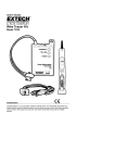
BTMPico Installation
Photograph 1
Page 1 of 3
-
+
-
+
Second
battery
block
First
battery
block
Drawing 1
Warning: use of this device is strictly limited to battery block voltage between 5 and 15 V DC.
Below 5V this device will not work and above 15V it may be damaged.
Please follow the steps below to connect a device to your battery. References will be made to
Photograph 1 and Drawing 1 above:
1. Connect the middle device pin (black alligator clip on photograph 1) to the negative post of the
first battery block to be monitored.
2. If two battery blocks are to be monitored, connect the right most device pin (green alligator clip
on photograph 1) to the negative post of the second battery block as shown on Drawing 1.
3. If only one battery block is to be monitored, leave the green wire unconnected.
4. Connect the left-most device pin (red alligator clip on photograph 1) to the positive post of the
first battery block as per Drawing 1.
Page 2 of 3
5. Using a plastic optical fiber, connect the blue device socket with the black USB/optical cable
socket.
6. Using another piece of plastic optical fiber, connect the black device socket with the blue
USB/optical cable socket.
The device is now ready and should start recording battery block data right away. The USB plug is to
be connected to a PC for data collection and analysis.
For instructions on how to access the recorded data using a PC based BTMPico Data Management
software, please read the BTMPico Data Management Software User manual.
Page 3 of 3