1
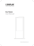
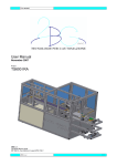
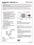
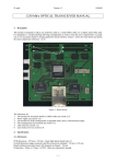
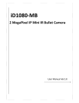
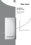
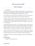
3D Artists Alligator Board Rev.2 The New Generation Electronic for 3D printers For Makers and Professionals Alligator Board Rev.2 – User Manual 3D-USM000001-R01 Rev 1 – Draft E Alligator Board Rev.02 3D Printer Electronic Board User Manual Document Number: Document Status: Release Date: 3D-USM000001-R01 Draft October 2014 This document discusses and illustrates the features, capabilities, and configuration requirements of the Alligator Board Rev.02. It is intended for technicians who are designing 3D printing solution with the Alligator Board. Disclaimer This document is provided "as is”. The Author(s) assumes no responsibility for the accuracy or completeness of the information presented in this document, which is subject to change without notice. In no event will the author(s) be liable for any direct, indirect, special, incidental or consequential damages, including lost profits, lost business or lost data, resulting from the use of or reliance upon the information, whether or not the author(s) has been advised of the possibility of such damages. Mention of third party products or services is for information purposes only and constitutes neither an endorsement nor a recommendation. 3D Artists www.3dartists.org Page 2 Alligator Board Rev.2 – User Manual 3D-USM000001-R01 Rev 1 – Draft E Related Information Documents [DOC-01] [DOC-02] 3D-SCH000001-R02.pdf 3D-SCH000002-R01.pdf Schematic Files: schematic files of the Alligator Board (rev02) Schematic Files: schematic files of the Piggy Expansion Module (rev01) [WEB-01] www.3DAsrtists.org Product information: describes the 3D Artists products features, benefits, and typical applications. This webpage also provides links to other product-related information located on the 3D Artists website. [WEB-01] https://github.com/3Dartists 3D Artists GitHub Page: The repository stores the designs files related to the 3D Artists products, including the Alligator Board. Part of the published material is the schematic files. Webpages Document Status Information 3D Artists technical documents are classified as either Draft, Advanced or Final: Draft: Advanced: Final: The draft documents contain information about the product which may be incomplete and a revision is required. This type of manual is subject to frequent updates The advanced documents are near to be the final revision, but still subject to be revised in same parts The final documents contains information about the final revision of the product and is subject to change only if an error is detected . 3D Artists www.3dartists.org Page 3 Alligator Board Rev.2 – User Manual 3D-USM000001-R01 Rev 1 – Draft E Summary Related Information............................................................................................................................................................ 3 Documents ...................................................................................................................................................................... 3 Webpages ....................................................................................................................................................................... 3 Document Status Information ............................................................................................................................................ 3 Overview ............................................................................................................................................................................. 5 Base Module Features .................................................................................................................................................... 6 Optional Expansion Piggy Module Features ................................................................................................................... 6 Board Dimensions ........................................................................................................................................................... 7 Alligator Board details and Configuration .......................................................................................................................... 8 Power Supply .................................................................................................................................................................. 8 Bed and Hot-End heaters ................................................................................................................................................ 8 Motor Drivers ................................................................................................................................................................. 9 End Stop interface .......................................................................................................................................................... 9 RTD Analog input .......................................................................................................................................................... 10 FAN driver output ......................................................................................................................................................... 10 Expansion Connectors .................................................................................................................................................. 11 General Purpose Expansion Connector .................................................................................................................... 11 Raspberry-PI Interface .............................................................................................................................................. 11 Piggy Expansion Module Connectors ........................................................................................................................ 12 Expansion Connectors Summary .............................................................................................................................. 13 USB Interfaces and Debug Port..................................................................................................................................... 14 Generic PWM outputs .................................................................................................................................................. 14 JTAG debug port ........................................................................................................................................................... 15 Microcontroller Flash ERASE ......................................................................................................................................... 15 Expansion Piggy ................................................................................................................................................................ 16 Motor Drivers ............................................................................................................................................................... 16 Typical Application ............................................................................................................................................................ 17 Alligator Board Base Module Typical Wiring Diagram .................................................................................................. 17 Alligator Board Piggy Expansion Module Typical Wiring Diagram ................................................................................ 18 3D Artists www.3dartists.org Page 4 Alligator Board Rev.2 – User Manual 3D-USM000001-R01 Rev 1 – Draft E Overview The new generation electronic for 3D printer. The Alligator is designed to be a complete and reliable solution as RepRap 3D printer electronic control board. The base module features everything you need to build a standard 3D printer, and with the expansion piggy this is the most complete solution for complex 3D printer. It is based on the 32 bit Cortex M3 ATSAM3X8EA microcontroller, the same CPU of Arduino Due. This represents a big step forward towards greater computing power, compared to the existing solution based on 8 bit mcu. This means that this product is well suited for any kind of 3D printer, and is the ideal solution for Delta models, which require more complex calculus for its coordinates resolution. The professional design of every part takes care of the needs of the most exigent makers, ensuring best performances in your application. Alligator Board Fetures 32 bit ARM Cortex M3 ATSAM3X8EA cpu running @ 84MHz (same Arduino Due cpu) Power supply: 12V÷24V 4 on board stepper motor driver (DRV8825) o Firmware configurable current up to 2.5A (no trimmer) o Firmware configurable step size 1/16 or 1/32 6 end-stop inputs compatible with both mechanical and optical/magnetic solution High current hot-end and bed heater output with high current connectors (up to 20A) 2 precision RTD measurement input, with configurable excitation current Dual output FAN driver Native USB OTG port USB to Virtual Com Port interface 10/100 Ethernet port, with unique MAC address (pre-programmed on-board chip) microSD Card slot 26pin Raspberry-PI interface with power 10 pin general purpose expansion connector with firmware selectable +3V3/+5V logic levels (for LCD or other custom add-ons) 3 PWM outputs, configurable for RGB led, servo motor or custom applications 32Mbit of FLASH memory 64Kbit of EEPROM Expansion connectors for Optional Piggy Module Board Filtered Power supply EMI and ESD protection on all interfaces High expansion interfaces capabilities 3D Artists www.3dartists.org Page 5 Alligator Board Rev.2 – User Manual 3D-USM000001-R01 Rev 1 – Draft E Base Module Features CPU Cortex M3 Atmel ATSAM3X8EA-AU 32Mbit (4Mbyte) of flash memory 640Kbytes of EEPROM memory High Current connector for power input, bed and hot-end heaters Filtered power supply to reduce EMI suscettivity ESD protected I/O 1. 2. Power Input 12-24Vdc 4x Stepper Motor driver based on Texas Instrument DRV8825 Up to 2.5A current, firmware configurable (no trimmer) 3. 4. 5. 6. 7. 8. 9. 10. 11. 12. 13. 14. Firmware Configurable microstep size (1/16 or 1/32) 6x End-Stop input compatible with both mecahnical and optical/magnetic solution High current Hot-End Heater driver output (High-Current connector) High current Bed Heater driver output (High-Current connector) 2x Precision analog input for temperature measurement with RTD (or thermocouple with external adapter) 2x External FAN output with PWM speed control 1x USB to Virtual COM port interface (micro USB connector) 1x Native microcontroller USB OTG port, firmware configurable (micro USB connector) microSD Slot 10/100 Ethernet Port with unique MAC address pre-programmed chip Expansion connector with 3 UART, or 6 GPIO, with firmware selectable +3V3/+5V logic levels 26pin Raspberry-PI Compatible expansion connector 3x Generic PWM open drain output for general purpose application (i.e. RGB LED) Figure 1 – Alligator Board Base Module Optional Expansion Piggy Module Features 1. 2. Power Input 12-24Vdc 3x Stepper Motor driver based on Texas Instrument DRV8825 Up to 2.5A current, firmware configurable (no trimmer) 3. 4. Firmware Configurable microstep size (1/16 or 1/32) 3x High current Hot-End Heater driver output (High-Current connector) 3x RTD precision analog input with selectable excitation current Figure 2 – Alligator Board Piggy Expansion Module 3D Artists www.3dartists.org Page 6 Alligator Board Rev.2 – User Manual 3D-USM000001-R01 Rev 1 – Draft E Board Dimensions 100mm 167mm Figure 3 – Alligator Board Base module dimensions 3D Artists www.3dartists.org Page 7 Alligator Board Rev.2 – User Manual 3D-USM000001-R01 Rev 1 – Draft E Alligator Board details and Configuration Power Supply The board can be powered with a regulated power supply in the range +12V, +24V. + + Main Power Supply [12V ÷ 24V] Figure 4 – Power supply High Current connector Bed and Hot-End heaters Both the bed heater and the hot-end heaters can be connected to the board using the high current connector as in Figure 5. Bed Heater Output + Hot-End Heater Output + Figure 5 – Hot-End and Bed heaters High Current connectors Voltage Output Maximum Current Output (Bed + Hot-End) Same as Main Power Supply Input 20A Table 1 – High Current Output electrical characteristics Note. The maximum current load for the high current output (bed + hot-end) is 20A. Then, for example, if you use a 8A hot-end heater, you should use a bed heater with a maximum current consumption of 12A. Note. Both bed and hot-end heaters outputs are driven at power input supply voltage. Thus, pay attention to not connect a 12V heaters when powering the board at 24V and vice-versa. 3D Artists www.3dartists.org Page 8 Alligator Board Rev.2 – User Manual Rev 1 – Draft E 3D-USM000001-R01 Motor Drivers The base board features four motor driver, implemented using the Texas Instrument DRV8825 controller. The configuration of the motor current can be via firmware, because the reference voltage required by the DRV8825 is generated using a DAC controlled by the microcontroller via an SPI interface. In this way the user can configure the motor current in a more accurate way, respect to the solution based on trimmers. This solution guarantees to the user that each motor has a precise current value, very important especially in delta architectures. The DRV8825 can be configured via firmware to operate at 1/16 step size or at 1/32 step size. On Board Motor driver Maximum Motor Current Current selection mode Motor step size 4 2.5A Firmware selectable in the range 0÷2.5A Firmware selectable 1/16 or 1/32 Table 2 – Base Module Motor Driver features STEPPER MOTOR 1 (X) STEPPER MOTOR 2 (Y) STEPPER MOTOR 3 (Z) STEPPER MOTOR 3 (extruder) Figure 6 – Motor Driver interface End Stop interface 3D Artists www.3dartists.org ES5 ES6 +5V ES ES3 ES4 +5V ES +5V ES ES1 ES2 The board features three identical block of end-stop interface, with two input on each one, for a total of six digital inputs. Each group makes available a regulated and filtered +5V supply voltage, useful to power active end-stop solutions, such as optical or magnetic ones. The presence of six channels allow the user to connect up to two end-stop for each axis, using for example a maximum and minimum position for each one. The Figure 7 shows an example of connection for a complete set of end-stop. The user can also use only three inputs, with only one end-stop for each axis. Page 9 Alligator Board Rev.2 – User Manual Rev 1 – Draft E 3D-USM000001-R01 Figure 7 – End Stop Interface RTD Analog input 1K p 4K ull-u 7 p p no ullpu up llup The board features two RTD inputs, which can be used to be connected to the bed and hot-end thermistors. RTD 1 RTD 2 Figure 8 – RTD temperature sensor interface The pull-up resistor can be selected acting on the dedicated dip-switch, as shown in the picture. It is also possible to directly connect an external analog source to the board input, positioning the dip-switch in the middle position, with no pull-up resistor. This option is useful to connect a thermocouple with its adapter, as shown in the following figure. +5V ES ES5 ES6 THERMOCOUPLE ADAPTER +5V SUPPLY ANALOG OUTPUT THERMOCOUPLE GROUND Figure 9 – Thermocouple connection example FAN driver output Two FAN can be connected to the board to the relative connector. In many cases the printer needs only one FAN to cool down the melted plastic just printed, but if you want to connect an additional FAN you can. Both the FAN can be driven with a variable PWM via standard G-CODE commands. FAN 1 FAN 2 Figure 10 – FAN driver interface 3D Artists www.3dartists.org Page 10 Alligator Board Rev.2 – User Manual Rev 1 – Draft E 3D-USM000001-R01 Expansion Connectors General Purpose Expansion Connector The Alligator Board features a general purpose expansion connector (J14), with seven GPIO (six of them connected to three microcontroller UART, then configurable as serial interface). An external LCD or any custom expansion can be connected to this connector. The voltage levels of the signals is firmware selectable, and can be set either to +3.3V or to +5V, depending on what kind of external module is connected. The electrical level of the digital lines can be selected acting on the EXP_VB_SEL line, as in Table 3. Microcontroller UART0_RX (or GPIO) UART0_TX (or GPIO) UART1_RX (or GPIO) UART1_TX (or GPIO) UART3_RX (or GPIO) UART3_TX (or GPIO) GPIO PA10 (pin3) PA11 (pin4) PA12 (pin5) PA13 (pin6) PD5 (pin18) PD4 (pin17) PB19 (pin90) EXP_VB_SEL PB20 (pin91) UART0_RX (or GPIO) UART0_TX (or GPIO) UART1_RX (or GPIO) UART1_TX (or GPIO) UART3_RX (or GPIO) UART3_TX (or GPIO) GPIO Bidirectional Buffer With Expansion Connector (J14) Logic Level Traslator Figure 11 – General Purpose Expansion Connector GPIO block diagram EXP_VB_SEL value 0 1 GPIO Electrical Level +5V +3.3V Table 3 – General Purpose Expansion Connector GPIO Voltage Selection 1 Function +5V USART0_TX (or GPIO) USART0_RX (or GPIO) USART2_TX (or GPIO) USART2_RX (or GPIO) PIN 1 3 5 7 9 2 4 6 8 10 Function +3V3 EXP_GPIO USART1_TX (or GPIO) USART1_RX (or GPIO) GND Table 4 – General Purpose Expansion Connector Pin-Out Raspberry-PI Interface Through J15 connector, the alligator board can be directly connected to a Raspberry-PI module with a standard 26pin flat cable. The +5V available on pin 2 and pin 4 is able to power-on the Raspberry-PI without the need to use an external dedicated power supply. 1 Function n.c. n.c. n.c. n.c. GND ERASE_CMD RPI_GPIO_2 RESET_CMD n.c. n.c. n.c. n.c. GND PIN 1 3 5 7 9 11 13 15 17 19 21 23 25 2 4 6 8 10 12 14 16 18 20 22 24 26 Function +5V +5V GND RPI_UART0_TX RPI_UART0_RX RPI_GPIO_1 GND RPI_GPIO_4 RPI_GPIO_5 GND RPI_GPIO_6 n.c. n.c. Table 5 – Raspberry-PI Expansion Connector Pin-Out 3D Artists www.3dartists.org Page 11 Alligator Board Rev.2 – User Manual Rev 1 – Draft E 3D-USM000001-R01 Piggy Expansion Module Connectors The alligator board has two expansion connector (J12 and J16) dedicated to the Optional Piggy Expansion Module (Figure 12). J12 1 J16 1 Figure 12 – Piggy Expansion Connectors details The J12 connector is used for the three additional motor driver signals of the Piggy Expansion, as in Table 6. The J16 connector is used for the three analog signal of the RTD. Function MOTOR_nRESET n.c. n.c. MOTOR_DIR5 MOTOR_STEP5 MOTOR_DIR6 n.c. MOTOR_STEP6 MOTOR_DIR7 MOTOR_STEP7 PIN 1 2 3 4 5 6 7 8 9 10 11 12 13 14 15 16 17 18 19 20 Function DAC_SCLK DAC_DIN DAC_nSYNC_EXP HE_HEAT_EN2 HE_HEAT_EN3 HE_HEAT_EN4 MOTOR_nFAULT +5V +3V3 GND Table 6 – J12 Piggy Expansion Connector (digital) Function +3V3_ANA AGND AGND AGND PIN 1 3 5 7 2 4 6 8 Function RTD_VALUE5 RTD_VALUE4 RTD_VALUE3 AGND Table 7 – J16 Piggy Expansion Connector (analog) Note. If you do not mount the Optional Expansion Piggy, these two connector can be used also with custom expansion board, or wired out for other applications. 3D Artists www.3dartists.org Page 12 Alligator Board Rev.2 – User Manual Rev 1 – Draft E 3D-USM000001-R01 Expansion Connectors Summary In the following table a summary of the expansion capabilities of the Alligator Board is explained. Signal Name USART0_TX (or GPIO) USART0_RX (or GPIO) USART1_TX (or GPIO) USART1_RX (or GPIO) USART2_TX (or GPIO) USART2_RX (or GPIO) EXP_GPIO ERASE_CMD (RPI_GPIO_0) RPI_GPIO_1 RPI_GPIO_2 RESET_CMD (RPI_GPIO_3) RPI_GPIO_4 RPI_GPIO_5 RPI_GPIO_6 MOTOR_nRESET (or GPIO) P_GPIO MOTOR_DIR5 (or GPIO) MOTOR_STEP5 (or GPIO) MOTOR_DIR6 (or GPIO) MOTOR_STEP6 (or GPIO) MOTOR_DIR7 (or GPIO) MOTOR_STEP7 (or GPIO) HE_HEAT_EN2 (or GPIO) HE_HEAT_EN3 (or GPIO) HE_HEAT_EN4 (or GPIO) MOTOR_nFAULT (or GPIO) EXT_PWM1 (or GPIO) EXT_PWM2 (or GPIO) EXT_PWM3 (or GPIO) RTD_VALUE5 RTD_VALUE4 RTD_VALUE3 Available On Connector / Pin J14 / pin 3 J14 / pin 5 J14 / pin 6 J14 / pin 8 J14 / pin 7 J14 / pin 9 J14 / pin 4 J15 / pin 11 J15 / pin 12 J15 / pin 13 J15 / pin 15 J15 / pin 16 J15 / pin 18 J15 / pin 22 J12 / pin 1 J12 / pin 3 J12 / pin 7 J12 / pin 9 J12 / pin 11 J12 / pin 15 J12 / pin 17 J12 / pin 19 J12 / pin 8 J12 / pin 10 J12 / pin 12 J12 / pin 14 J5 / pin 3 J5 / pin 2 J5 / pin 1 J16 / pin 2 J16 / pin 4 J16 / pin 6 High Level Voltage Firmware selectable +3.3V / +5V Firmware selectable +3.3V / +5V Firmware selectable +3.3V / +5V Firmware selectable +3.3V / +5V Firmware selectable +3.3V / +5V Firmware selectable +3.3V / +5V Firmware selectable +3.3V / +5V +3.3V +3.3V +3.3V +3.3V +3.3V +3.3V +3.3V +3.3V +3.3V +3.3V +3.3V +3.3V +3.3V +3.3V +3.3V +3.3V +3.3V +3.3V +3.3V +3.3V +3.3V +3.3V Analog input only Analog input only Analog input only Note Available as GPIO only if Raspberry-PI is not connected to the Alligator Board Available as GPIO only if the Piggy module is not installed on the Alligator Board Configurable also as PWM output Configurable also as PWM output Configurable also as PWM output Available as GPIO only if the Piggy module is not installed on the Alligator Board Table 8 – Expansion Connector summary 3D Artists www.3dartists.org Page 13 Alligator Board Rev.2 – User Manual Rev 1 – Draft E 3D-USM000001-R01 USB Interfaces and Debug Port The Alligator Board features two USB interfaces (see Figure 13 for details): Native microcontroller USB port (USB OTG port) USB/UART VCP (Virtual Com Port) CABLE_DETECTION FTDI VCP interface UART DEBUG PORT USB VCP port MUX Microcontroller Raspberry-PI interface USB native port Figure 13 – USB interfaces and Debug UART block diagram The Native USB port is directly connected to and controlled by the microcontroller. The USB VCP interface is implemented using an FTDI USB to UART converter, connected to the debug UART of the microcontroller. The debug UART of the microcontroller is connected also to the raspberry-PI connector through a multiplexer. In this way the Alligator Board can be controlled and programmed either using a standard PC or via the Raspberry-PI. The multiplexer is controlled with this logic: when the USB connector is unplugged into the USB-VCP connector, the debug UART signals are routed to the raspberry connector. In this way if the Raspberry-PI is connected to the Alligator Board it can either control and also reprogram the cpu firmware, without any other connections or configuration. when the USB connector is plugged into the USB-VCP connector, the debug UART signals are routed to USB to UART converter. In this way the user can control the 3D printer using a standard PC Note: If you connect the USB cable to the FTDI port (ref.8 on Figure 1), the raspberry UART is not available. The user can continue to use the Raspberry-Pi signals excepts for the RPI_UART0_TX (pin 8) and RPI_UART0_RX (pin 10) Warning: Native port has OTG function, they are directly connected to 5V power! Do not connect Native USB port to the PC in presence of 12-24V power input. Communicate with Alligator and with your printer only from the USB/UART port. Native port should be used only as Host OTG. Native port connected directly to the PC can be used only for board testing without 12-24V power input (for expert users only!) Generic PWM outputs The board features three generic PWM outputs, that can be used for example to connect a LED for printer illumination, which can be a single color LED (white for example) using only one channel, or an RGB LED using all three channel. These outputs can be also configured via firmware to control servo motors or any kind of general purpose application. PWM Out 1 PWM Out 2 PWM Out 3 Figure 14 – PWM output interface 3D Artists www.3dartists.org Page 14 Alligator Board Rev.2 – User Manual Rev 1 – Draft E 3D-USM000001-R01 JTAG debug port For expert users, a JTAG port is available. This port can be used to debug or program the Alligator board, using the preferred IDE and JTAG adapter. 10pin JTAG PORT Figure 15 – JTAG Connector Microcontroller Flash ERASE The Alligator Board microcontroller flash can be erased in the following two ways: [OPTION A] – Acting on the S4 Dip-Switch [OPTION B] – Through the Raspberry-PI header Reset Button (S1) ERASE Normal Operation Figure 16 – S4 Dip-Switch configuration [OPTION A] – To erase the microcontroller using the S4 dip-switch: Turn on the Alligator Board Move the S4 dip-switch in ERASE Mode (see Figure 16) Push the reset button (S1) Wait for the flash erase operation to be completed (about 1s) Move the S4 dip-switch in Normal Operation Mode (see Figure 16) Push the reset button (S1) [OPTION B] – To erase the microcontroller using the ERASE_CMD signal available on the Raspberry-PI expansion connector: Turn on the Alligator Board Set a Low Logic Level (<1V) on the ERASE_CMD signal (pin 11 of J15 connector, see Table 5) Wait for the flash erase operation to be completed (about 1s) Set a High Logic Level (+3.3V) on the ERASE_CMD signal (pin 11 of J15 connector, see Table 5) 3D Artists www.3dartists.org Page 15 Alligator Board Rev.2 – User Manual Rev 1 – Draft E 3D-USM000001-R01 Expansion Piggy Motor Drivers The Expansion Piggy module board features three motor driver, implemented using the Texas Instrument DRV8825 controller. The configuration of the motor current can be via firmware, because the reference voltage required by the DRV8825 is generated using a DAC controlled by the microcontroller via an SPI interface. In this way the user can configure the motor current in a more accurate way, respect to the solution based on trimmers. This solution guarantees to the user that each motor has a precise current value, very important especially in delta architectures. The motor driver step-size is fully configurable for each motor S2 dip-switch (see Table 10 for details) On Board Motor driver Maximum Motor Current Current selection mode Motor step size 3 2.5A Firmware selectable in the range 0÷2.5A Fully configurable via dip-switch Table 9 – Piggy Expansion Module Motor Driver features S2.1 S2.2 MOTOR 1 S2.3 S2.4 S2.5 MOTOR 2 S2.6 S2.7 S2.8 MOTOR 3 S2.9 S2.10 N.C. ON OFF Figure 17 – S2 Dip-Switch configuration Step Mode Full Step 1/2 Step 1/4 Step 1/8 Step 1/16 Step 1/32 Step Motor 1 S2.1 S2.2 S2.3 OFF OFF OFF ON OFF OFF OFF ON OFF ON ON OFF OFF OFF ON ON OFF ON S2 Configuration Motor 2 S2.4 S2.5 S2.6 OFF OFF OFF ON OFF OFF OFF ON OFF ON ON OFF OFF OFF ON ON OFF ON S2.7 OFF ON OFF ON OFF ON Motor 3 S2.8 S2.9 OFF OFF OFF OFF ON OFF ON OFF OFF ON OFF ON Table 10 – Piggy Expansion Module Motor Step size settings 3D Artists www.3dartists.org Page 16 Alligator Board Rev.2 – User Manual Rev 1 – Draft E 3D-USM000001-R01 Typical Application Alligator Board Base Module Typical Wiring Diagram Hot-End Heater Output - + Bed Heater Output + + + Main Power Supply [12V ÷ 24V] STEPPER MOTOR 1 (x) + - FAN 1 + - FAN 2 +5V ES STEPPER MOTOR 2 (y) ES1 (x.max) ES2 (x.min) +5V ES ES3 (y.max) ES4 (y.min) STEPPER MOTOR 3 (z) +5V ES ES5 (z.max) ES6 (z.min) STEPPER MOTOR 4 (extruder) RTD 1 RTD 2 PWM Out 1 PWM Out 2 Expansion Connector microSD card er ry -P I pb Ra s Na tiv US e M B CU US B/ UA RT PWM Out 3 10/100 Ethernet Figure 18 – Alligator Board Base Module Wiring Diagram 3D Artists www.3dartists.org Page 17 Alligator Board Rev.2 – User Manual Rev 1 – Draft E 3D-USM000001-R01 Alligator Board Piggy Expansion Module Typical Wiring Diagram + Hot-End Heater #2 Output + Hot-End Heater #3 Output + STEPPER MOTOR 2 + STEPPER MOTOR 1 Hot-End Heater #1 Output Main Power Supply [12V ÷ 24V] STEPPER MOTOR 3 RTD #1 RTD #2 RTD #3 Figure 19 – Alligator Board Piggy Expansion Module Wiring Diagram 3D Artists www.3dartists.org Page 18