1
HP16C Emulator Module for the HP-41CX
User’s Manual and QRG.
Written and Programmed by Greg J. McClure and Ángel M. Martin
September 4, 2015
(c) Martin-McClure
Page 1 of 63
September 2015
HP16C Emulator Module for the HP-41CX
This compilation revision 1.5.3
Copyright © 2015 Ángel M. Martin and Greg J. McClure
Published under the GNU software licence agreement.
Original authors retain all copyrights, and should be mentioned in writing by any part utilizing this
material. No commercial usage of any kind is allowed.
Screen captures taken from V41, Windows-based emulator developed by Warren Furlow.
See www.hp41.org
Acknowledgments.Special thanks go to Greg McClure for his tremendous work on the 16C Emulator module – his 16C
Buffer design and handling routines, together with the “big math” algorithms are the heart and soul of
this module.
Thanks to Monte Dalrymple for his feedback on the overlay and this manual, and for his thorough
testing of the beta software and release candidates.
Thanks to Michael Fehlhammer for making the 16C overlay a reality in such a short time even before
the module release.
(c) Martin-McClure
Page 2 of 63
September 2015
HP16C Emulator Module for the HP-41CX
Table of Contents.
1. Introduction
1.1.
1.2.
1.3.
1.4.
1.5.
Introduction.
Page#4 Library and Bank-Switching
Organization of the Manual and Remarks
Function Index at a glance
New/Original Function Table
5
5
6
7
10
2. The 16C Data Structure
2.1
2.1.1
2.1.2
The Martin-McClure Buffer
16C Stack Operation
Stack and memory Functions
11
11
12
2.2.
2.2.1
Data Input with 16NPT
The 16C Keyboard and Overlay
13
16
2.3.
2.3.1
2.3.2
Data Output with SHOW and WINDOW
The true meaning of GRAD
Data Formats Summary
17
18
18
3. What’s New & Different
3.1
Differences from the Original
3.1.1 Number Entry and FLOAT mode
3.1.2 Flags as Semaphores: CY and OOR
3.1.3 Status and Flashing messages
3.1.4 Prompting Functions
3.1.5 Test functions launchers
3.1.6 ISZ/DSZ and function Parameters
3.1.7 Square Root and Square power
3.1.8 A few examples: Gray code, bit extraction, add w/ CY
19
20
21
23
24
25
26
27
28
3.2
3.2.1
3.2.2
3.2.3
3.2.4
3.2.5
New Functionality added
Rotations Launcher
Shifting and Bit operations Launcher
Bases and Signed Modes Launcher
Left and Right Launchers
Launcher Shortcuts Map
29
29
29
30
31
32
3.3.
3.3.1
Remaining Functions not on Launchers
Last Function and Programmability
33
34
(c) Martin-McClure
Page 3 of 63
September 2015
HP16C Emulator Module for the HP-41CX
3.4.
3.4.1
3.4.2
3.4.3
3.4.4
3.4.5
3.4.6
Individual Function descriptions
Negative Logic Functions
Word size related functions
Left and Right Justification
Bit Reversal
Multi-Position Shifting
Storage and Retrieval in X-Memory
35
35
35
36
36
37
38
4. Diagnostics Functions.
4.0
4.1.
4.2
4.2.1.
4.2.2.
4.2.3.
4.2.4.
4.2.5
4.2.7.
4.2.8.
Silent and Loud Modes
An alternative to the 16C keyboard
A few Development Aids
Buffer Registers handling
Buffer Data Types
Doubling and Halving
Digit Justification, Reversal and Decimal Sum
Test for Maximum Negative Value
Recalling the current Base value
Quick Hex<>Dec
39
40
41
41
42
42
43
44
45
45
Appendices.
a.1
a.2
a.3
a.4
Maximum values as function of word size
The Hexadecimal Number system
Program Examples
Buffer Technical Details
(c) Martin-McClure
Page 4 of 63
46
47
50
52
September 2015
HP16C Emulator Module for the HP-41CX
Computer Science for the HP-41CX
1. Introduction.
At long last, a complete solution for the Computer Scientist on the HP-41 platform is finally available
in the form of the HP-16C Emulator module.
This module provides a comprehensive feature set that includes all the functionality from the original
HP-16C, plus a few new surprises and extensions added to the design. Support for up to 64-bit word
size is provided in all functions – beyond any previous attempt implemented on the 41 system ever
before.
The design takes full advantage of the alphanumeric capabilities of the 41, in particular the 24character LCD for more convenient number entry and display. Prompting functions and X-Memory
backup enhance the usability and go beyond the original machine. Use them in manual operation or in
a program, all functions are completely programmable.
Auxiliary FAT, Bank-switching and Page#4 Library.
The 16C Emulator module comes loaded with functions and a rich feature set – yet it only takes a
single page (i.e. half port) on the 41 ROM module bus. Its structure consists of four bank-switched 4k
blocks, with functions arranged in two Function Address tables – the main one filled-up with 64
functions plus an auxiliary one containing additional sub-functions. All are programmable, and easily
accessed using dedicated function launchers. Plus a complete 16C Keyboard overlay is available for
instant plug-and play functionality.
The 16C Emulator is a Library#4-aware module: it makes extensive usage of the library routines for
more efficient execution as well as management of the auxiliary FAT and sub-function launchers which relies on the presence of the Library#4 installed on the system. The Library#4 has been
updated for the 16C Emulator, thus ensure you have revision “O1”, with MOD file date August 2015.
The last remark is regarding the CX dependency: designed for the CX version of the 41 OS, the code
occasionally uses subroutines from the CX OS code. This was a compromise to enhance the
functionality at the economy of ROM space – as it avoided having to replicate large code streams
already available on the CX. Don’t use this module on a plain 41C or CV machine, it’ll have surely
unexpected and probably unwanted results.
The module checks for the presence of the dependencies, i.e. the Library#4 and the CX.-- If the
Library#4 is missing or the machine is not a CX the errors will halt it to avoid likely problems. Note
also that this module is not compatible with pages#6 and 7 – avoid plugging it in those locations.
Remember: The HP16C Emulator module extensively uses routines and functions from the Page#4
Library. Make sure the Library#4 revision “O1” (or higher) is installed on your system or things can go
south. Refer to the Page#4 Library documentation to properly configure the Library#4 before use.
(c) Martin-McClure
Page 5 of 63
September 2015
HP16C Emulator Module for the HP-41CX
Organization of this manual.
We have no intention to duplicate the HP-16C Computer Scientist Manual – which is the best
reference to learn about the functions and concepts behind this module. This manual won’t teach you
the intricacies of the Carry and Out of Range flags, or the binary concepts behind the 1’s or 2’s
complement signed modes for instance. You’re encouraged to read the original 16C manual if needed.
It is however important to document the main design criteria applied to the 16C Emulator module and
the derived consequences for its use. Special attention has been put to the new and additional
functions, as well as documenting the small differences that may exist in a few functions when
compared to their original implementation on the 16C calculator.
It is expected that the reader be already familiar with the HP-41 environment, so as to be comfortable
keying instructions and operating the machine. A basic knowledge of the 41 system memory structure
and programming will be very useful if you also want to use the 16C module functions in your own
programs.
This module employs several powerful concepts also present in other advanced modules, such us a
secondary FAT to hold auxiliary sub-functions; several function launchers that group functions and
sub-functions by related functionality; and the LAST Function facility to re-execute the last function
(or sub-function) called - to mention just the most important ones. You may be familiar with all these
had you already used the SandMath, SandMatrix or PowerCL modules. You don’t need a 41-CL to run
this module but obviously its tremendous speed advantage makes it the best possible choice of
hardware.
Some remarks about the implementation.
Emulating the complete capabilities of the original 16C machine has been a tall order, only possible
thanks to a fortuitous combination of dedication and skills from both co-authors. Greg’s programming
skills have been put to a good use in the base conversion and “big math” algorithms - which work
seamlessly integrated into the module completely behind the scenes.
The double precision multiplication and division in particular are highlights of the module, taking up
the third bank in its entirety by themselves – which speaks volumes about their intricate design and
complex implementation.
From my part this module brings it all together home in many ways; starting with the advanced
concepts borrowed from the 41Z Complex module (dealing with auxiliary buffers for data storage and
abstraction data layers above the native real numbers support on the 41 OS); from the SandMath and
PowerCL modules (pioneering the function Launchers) and of course the heavy reuse of Auxiliary
FATS and sub-function management leveraging the Library#4 design way beyond its initial design
scope.
All in all, this module is nothing short of an improbable amazing feat if you ask me, and I think I
speak on both Greg’s and my own behalf to say it’s an important contribution to the 41 legacy. It has
been a very rewarding project, and a great learning opportunity for me as well – thank goodness Greg
was on watch to keep all those whimsical components of the 16C intricacies at bay many times
during the development, when I was getting completely confused!
PS. The trademark “Martin-McClure” is a result of a virtual coin toss and some consideration as to the
“ringing” of the words – but under no circumstance denotes any priority in the order of the names.
(c) Martin-McClure
Page 6 of 63
September 2015
HP16C Emulator Module for the HP-41CX
Function index at a glance.Without further ado, here are all 125 functions included in the main and auxiliary FATs.
#
1
2
3
4
5
6
7
8
9
10
11
12
13
14
15
16
17
18
19
20
21
22
23
24
25
26
27
28
29
30
31
32
33
34
35
36
37
38
39
40
41
42
43
44
45
46
47
48
49
Function
-HP-16C+
16C _
16# _ _ _
16$ _
16+
1616*
16/
16SQRT
16WSZ _ _
1CMP
2CMP
AND
ASR
b? _ _
BINM
Cb _ _
DBL*
DBL/
DBLR
DECM
FLOAT
HEXM
LJY
MASKL _ _
MASKR _ _
NOT
OCTM
OR
RL
RLC
RLCN _ _
RLN _ _
RMD
RR
RRC
RRCN _ _
RRN _ _
Sb _ _
SHOW
SLN _ _
SRN _ _
STATUS
UCMP
WINDOW _
XOR
LEFT _
MOD _
ROT _
Description
Shows Library#4 Splash
Main 16C Keyboard Launcher
WEX Subfunction by index
XEQ sub-function by Name
Integer mode addition
Integer mode subtraction
Integer mode multiplication
Integer mode Division
Square Root
Sets Word Size
Sets 1's Complement Mode
Sets 2's Complement mode
Logical Intersection
Arihtmetic Shift Right
Bit Set testing
Binary Base display
Clears bit
Double precision 16*
Double Precision 16/
Double Prec. Remainder
Decimal base display
Floating Point mode
Hexadecimal Base display
Left Justify
Builds a Left-justified Mask
Builds a Right-justified Mask
Logical Inversion
Octal Base display
Logical Addition
Rotate Left (one pos.)
Rotate Left thru Carry
RLC n-positions
Rotate Left n-positions
Division Remainder
Rotate Right (one pos.)
Rotate Right thru Carry
RRC n-positions
Rotate Right n-positions
Set bit
Shows value in 16X
Shift Left n-positions
Shift Right n-positions
Shows Status Info
Sets Unsigned mode
Shows the Window registers
Exclusive OR
Left Launcher
Modes Launcher
Rotations Launcher
(c) Martin-McClure
Input
none
see 16C keyboard overlay
Prompts for index
Prompts for name
values in 16X and 16Y
values in 16X and 16Y
values in 16X and 16Y
values in 16X and 16Y
value in 16X
prompts for word size
none
none
values in 16X and 16Y
value in 16X
value in 16X, bit# in prompt
none
value in 16X, bit# in prompt
values in 16X and 16Y
values in 16X, 16Y, 16Z
values in 16X, 16Y, 16Z
none
none
none
value in 16X
# of bits in prompt
# of bits in prompt
value in 16X
none
values in 16X and 16Y
value in 16X
value in 16X
value in 16X and prompt
value in 16X and prompt
values in 16X and 16Y
value in 16X
value in 16X
value in 16X and prompt
value in 16X and prompt
value in 16X, bit# in prompt
value in 16X
value in 16X and prompt
value in 16X and prompt
base and complement data
none
values in FX buffer regs
values in 16X and 16Y
prompts for function
prompts for function
prompts for function
Page 7 of 63
Result
Flashes splash msg
executes function
executes function
executes function
Result in 16X, stack drops
Result in 16X, stack drops
Result in 16X, stack drops
Result in 16X, stack drops
result in 16X, argument to 16L
flashes size on LCD
changes mode, sets flag 1
changes mode, sets flag 2
Result in 16X, stack drops
result in 16X, argument to 16L
YES/NO, skips line if false
changes displayed base
result in 16X, argument to 16L
Result in 16X & 16Y, stack drops
pushes value into 16C stack
pushes value into 16C stack
changes displayed base
supresses displaying mode!
changes displayed base
Result in 16X, #pos in 16Y
pushes value into 16C stack
pushes value into 16C stack
result in 16X, argument to 16L
changes displayed base
Result in 16X, stack drops
result in 16X, argument to 16L
result in 16X, argument to 16L
result in 16X, argument to 16L
result in 16X, argument to 16L
pushes value into 16C stack
result in 16X, argument to 16L
result in 16X, argument to 16L
result in 16X, argument to 16L
result in 16X, argument to 16L
result in 16X, argument to 16L
Puts value chars in ALPHA
result in 16X, argument to 16L
result in 16X, argument to 16L
Shows machine status msg
changes mode, sets flag 0
shows FX registers on LCD
Result in 16X, stack drops
executes function
executes function
executes function
September 2015
HP16C Emulator Module for the HP-41CX
50
51
52
53
54
55
56
57
58
59
60
61
62
63
64
0
1
2
3
4
5
6
7
8
9
10
11
12
13
14
15
16
17
18
19
20
21
22
23
24
25
26
27
28
29
30
31
32
33
34
35
36
37
38
-16C STACK
16ABS
16CHS
16ENT^
16NPT
16RCL _ _
16RDN
16RUP
16STO _ _
16X<> _ _
16X<>Y
CL16X
CL16ST
LST16X
X?Y _
-16C FAT2
BIT _
SHF _
RIGHT _
16APN
16x^2
16X=0?
16X#0?
16X<0?
16X<=0?
16X>0?
16X>=0?
16X=Y?
16X#Y?
16X<Y?
16X<=Y?
16X>Y?
16X>=Y?
16X^^^
DSZ
GET16
ISZ
LOW16^
NAND
NOR
REV
RJY
SAVE16
SL
SR
WSFIT
X?0 _
XNOR
#BITS
FCAT _
-TESTING
16KEYS
16WSZ?
2DIV
Shows Copyright & Sound
Absolute value
Changes 16X sign
Pushes 16X one level up
Main Data Input function
Recalls value from memory
Rolls the 16C stack down
Rolls the 16C stack Up
Stores 16X in memory
Exchanges the 16X and mem
Swaps 16X and 16Y
Clears the 16X register
Clears al the 16C stack
Recalls last value used
XY Tests launcher
Section header
Bit Functions Launcher
Shift/Bist Launcher
Right Launcher
Append String to Value
Squares 16X
tests 16X equal to zero
tests 16X not equal to zero
tests 16X less than zero
tests 16X less or equal to 0
tests 16X greater than zero
tests 16X greater or equal 0
tests 16X equal to 16T
tests 16X not equal to 16Y
tests 16X less than 16Y
tests 16X less/equal to 16Y
tests 16X greater than 16Y
tests 16X great/equal to 16Y
enters 16X in all stack levels
Decrement and skip if Zero
Gets 16C buffer from X-Mem
Increment and skip if zero
Enters x into 16X register
Negative AND
Negative OR
Reverses bits in word
Right Justifies the value
Saves 16C buffer in X-Mem
Original Shift Left function
Original Shift Right function
Fits the word size to 16X value
Tests to zero Launcher
Negative XOR
Gets sum of selected bits
Sub-function Catalog
Section header
Mass-Key Assignments (*)
Retrieves current word size set
Halves the content of 16X
(c) Martin-McClure
n/a
value in 16X
value in 16X and compl mode
values in 16C stack
Characters in ALPHA
values in data registers
values in 16C stack
values in 16C stack
value in 16X and prompt
values in 16X and data regs
values in 16X and 16Y
anything in 16X
anything in 16C stack
value in 16L reg
XY tests launcher
section header
prompts for function
prompts for function
prompts for function
Partial String in Alpha
value in 16X
value in 16X
value in 16X
value in 16X
value in 16X
value in 16X
value in 16X
values in 16X and 16Y
values in 16X and 16Y
values in 16X and 16Y
values in 16X and 16Y
values in 16X and 16Y
values in 16X and 16Y
value in 16X
content of R00 data reg
X-mem file name in ALPHA
content of R00 data reg
real number value in x
values in 16X and 16Y
values in 16X and 16Y
value in 16X
value in 16X
X-mem file name in ALPHA
value in 16X
value in 16X
value in 16X
X0 tests launcher
values in 16X and 16Y
value in 16X
has hot-keys
section header
Prompts Y/N?
ws data from buffer
value in 16X
Page 8 of 63
Flashes message & sounds
result in 16X, argument to 16L
result in 16X, argument to 16L
16X in entered to 16Y
next value entered in 16X
value from memory into 16X
16C stack rolled down
16C stack rolled up
16X stored in data registers
16X and data regs exchanges
16X and 16Y exchanged
16X is zeroed
the 16C stack is zeroed
pushes 16L into 16X
executes function
n/a
executes function
executes function
executes function
Appends to Exisiting Value
result in 16X, argument to 16L
YES/NO, skips line if false
YES/NO, skips line if false
YES/NO, skips line if false
YES/NO, skips line if false
YES/NO, skips line if false
YES/NO, skips line if false
YES/NO, skips line if false
YES/NO, skips line if false
YES/NO, skips line if false
YES/NO, skips line if false
YES/NO, skips line if false
YES/NO, skips line if false
16X is replicated
R00 decrements, skip iz aero
new 16C buffer is in place
R00 increments, skip iz aero
new value in 16X
Result in 16X, stack drops
Result in 16X, stack drops
result in 16X, argument to 16L
Result in 16X, #pos in 16Y
buffer saved in X-Mem file
result in 16X, argument to 16L
result in 16X, argument to 16L
ws changed
executes function
Result in 16X, stack drops
Returns sum of bits to 16X
enumerates sub-functions
n/a
Makes / Removes KA
Shows ws and puts it in 16X
result in 16X, argument to 16L
September 2015
HP16C Emulator Module for the HP-41CX
39
40
41
42
43
44
45
46
47
48
49
50
51
52
53
54
55
56
57
58
59
60
2MLT
A2FX
BASE?
CHKBB
CLRFX
D>H
DGD
DGLJ
DGRV
EX2FX
FX2EX
FXSZ?
H>D
H=L
L-H
L<>H
LDZER
MNV?
TS/L
WSMAX
X-LA
(c)
Doubles the content of 16X
Alpha to FX registers
Recalls base to 16X
Checks & Builds the 16C buffer
Clears FX buffer registers
Decimal to Hex
Decimal Digit Sum
Digit Left-justify
Digit Reversal
Copies the EX regs to the FX regs
Copies the FX regs to the EX regs
Shows number of non-zero chrs in FX
Hex to Decimal
Copies the Low bits into the High bits
Moves the Low bits to the High bits
Swaps Low and High 16X bits
Shows Leading Zeros
Test for Maximum Negative Value
Toggles Silent/Loud Mode
Shows maximum value for ws
Appends chr(X) to laft-Alpha
Shows Copyright Message
value in 16X
String in ALPHA
none
none
none
Value in X-reg
Value in 16X
Value in X-reg
Value in 16X
Binary Data in EX regs
Chars Data in FX regs
none
Hex String in Alpha
Data in 16X
Data in 16X
Data in 16X
Data in 16X
Value in 16X
none
ws data in buffer
Crh value in X
none
result in 16X, argument to 16L
Chars transferred to FX regs
Base value in 16X
16C Buffer in Memory
FX regs cleared (reset)
Hex string in Alpha
Shows sum and enters it
Digits left-Justified
Reversed digits in 16X
Chars written in FX Regs
Binary Data in EX regs
Number of characters in X
Result in X-register
Copies X to b13
Moved X to b13
X-reg and b13 swapped
Leading Zeros added
YES/NO, skips line if false
Active mode toggled
shows value in x
Appended to left Alpha
Shows message
If you’re familiar with the 16C calculator you’ll no doubt recognize the majority of functions in the
main FAT – as such as been the criteria for function FAT allocation. Their functionality and operation
should be pretty much identical to their original counterparts, but there are a few differences that will
be covered later in the manual.
Hopefully you’re also intrigued about the new additions to the function set (located in the auxiliary
FAT), and can probably guess their scope and intention – that will be the subject of dedicated sections
as well, as they are likely to add some surprises to the digital mix. Refer to the table in next page for
a quick comparison between new, modified and original functions in the emulator.
Always ensure that Revision “O1” or higher of the Library#4 is installed on the system.
(c) Martin-McClure
Page 9 of 63
September 2015
HP16C Emulator Module for the HP-41CX
(c) Martin-McClure
Page 10 of 63
September 2015
HP16C Emulator Module for the HP-41CX
2.1. The Martin-McClure Buffer
Without doubt the 16C-Buffer is the cornerstone of the 16C Emulator module. Designed to fulfill the
storage requirements for 64-bit data values and provide available scratch registers for data
management and auxiliary calculations, this buffer is automatically created and maintained by the
calculator behind the scenes - all transparent to the user.
Even if you can use the module completely unaware of the 16C buffer, knowing the fundamentals on
its structure and operation will largely increase you understanding of the module - significantly
smoothing the learning curve. Those wanting to know more should refer to appendix B for a more
detailed description of the buffer registers and design.
Data Size and Registers: the problem at hand.
Because the data values can be as large as 64-bit, the 56-bit standard 41C registers are not sufficient
to hold the values in all cases- even if we were to use up all of them in a custom data format.
The solution implemented uses two standard hp-41 registers for each 16C value, with each register
holding 32-bits worth of information. We’ll call those registers the “lower bits” and the “higher bits”
registers. This is so regardless of the selected word size, thus the higher bits register will be empty
when the value can be expressed by 32- or less number of bits.
The 16C Stack is the first abstraction layer you need to become familiar with. Like its “standard”
counterpart {X,Y,Z,T,L}, the 16C Stack consists of 5 logical 64-bit registers, named 16X, 16Y, 16Z,
16T, and 16L (or Last16X). Physically each one of these is made as the logical combination of the
standard stack register of the same name plus another register from the 16C Data Buffer. As you’d
expect, the standard stack contains the “lower bits” half of the value, whilst the buffer register holds
the “higher bits”.
Register
16X
16Y
16Z
16T
16L
2.1.1
Lower Bits
X
Y
Z
T
L
+
Upper Bits
b13
b12
b11
b10
b14
16C Stack Operation functions.
A set of functions is provided to operate on the 16C registers as whole unit – including both the lower
and upper bits halves simultaneously. It is important that you remember that the standard functions
of the calculator will only access the lower bits halves, and thus you should use the 16C functions
instead – unless you’re already on the grand-master level and begin hacking around.
These functions include the 16C stack handling (usual suspects here: 16ENT^, 16X<>Y, 16RDN,
16RUP, CL16X, CL16ST) as well as exchange with the other data registers in the calculator
memory: 16STO, 16RCL, and 16X<>. The last three are also programmable using the “nonmerged” approach – whereby the target register number is entered as a follow-up line in the program.
(c) Martin-McClure
Page 11 of 63
September 2015
HP16C Emulator Module for the HP-41CX
2.1.2. Stack and Memory Functions.
The table below summarizes all functions and sub functions related to stack and memory handling.
Function
16ENT^
LOW16^
16X<>Y
16RDN
16RUP
16X^^^
LST16X
CL16X
CL16ST
16STO _ _
16RCL _ _
16X<> _ _
SAVE16
GET16
Description
Pushes 16X into the 16C stack
Pushes x into 16X level
Swaps 16X and 16Y levels
Rolls down the 16C stack
Rolls up the 16C stack
Copies 16X into all 16C levels
Recalls the last value to 16X
Clears the 16X level
Clears all 16C stack
Stores 16X in memory
Recalls value from memory
Exchanges 16X and memory
Writes 16C stack to X-Mem
Reads 16C stack from X-mem
Comment
Lifts 16C Stack
Lifts 16C stack
Lifts 16C stack
Uses two data regs
Lifts 16C Stack
Uses two data regs
Creates “H”-type file
Only one buf allowed
Data registers Usage and Required SIZE
Max 16RG#
n/a
16R00
16R01
16R02
16R03
16R04
16R05
16R06
16R07
16R08
16R09
16R10
16R11
…
Size
1
2
3
4
5
6
7
8
9
10
11
12
13
14
15
16
17
18
19
20
21
22
23
24
25
Note that 16STO, 16RCL and 16X<> are prompting functions.
As explained before, two data registers are used to store the 16X
values in memory. Refer to the table on the left for a
correspondence between the register# used in the prompt and the
actual SIZE required in the calculator to allow for the range of 16C
data registers needed.
Note that R00 is used by the ISZ and DSZ sub-functions as the
“indirect” register – therefore and to avoid conflicts the actual
registers usage in the 16C registers scheme begins with {R01 &
R02} for the 16C- version of “16R00”. This makes them compatible
with each other so you don’t have to worry about it.
Remember that you can also use the 41-native functions ISG and
DSE instead for a more powerful implementation that allows you to
choose the indirect register used. In that case you need to mind
the potential register conflicts!
…
Now that we’ve got the data requirements and design considerations out of the way let’s see how to
go about introducing and reviewing actual 16C values in the calculator.
(c) Martin-McClure
Page 12 of 63
September 2015
HP16C Emulator Module for the HP-41CX
2.2. Data Input. - { 16NPT , LOW16^ , 16APN }
If the 16C buffer is the invisible heart of the module then the 16NPT function is its visible
counterpart. This is the function you’ll be using most of the time to enter the data values and
arguments for your calculations – regardless of the selected base and complement mode set.
When invoked, the function prompts for the digit values to input, showing the selected base on the
left side of the display. The data is input as alphanumerical digits on the LCD display during the
process. Only the appropriate digits for each base will be allowed.
You can enter up to 24 digits at a single time, or split the entry in three different sub-sections (called
“partials”) if so preferred. Obviously for large values in Binary mode this last method will become
necessary, but for all other bases a single partial is enough to hold the maximum numbers allowed
even for a 64-bit word size.
The digit entry can be completed only partially by pressing the SST key – this will commit the digits
to the 16C buffer and will present the base prompt anew, ready for the next partial entry. The second
partial is then appended to the first one, and this can be repeated again for the third (and last) partial
– so even a 64-bit value in binary can be entered using three segments of data.
The flag annunciators are temporarily “borrowed” by 16NPT to show you which partial you’re working
on at any time. Thus you’ll see “1”, “12”, or “123” depending on which one of the three partial
screens you’re in at any given time. Once completed, their status will revert back to their previous
values prior to executing 16NPT.
Note that the back-arrow key will either delete the current digit, or cancel the function if there are no
more digits left on the display. This will show the value in 16X previous to the execution of 16NPT, or
enter the current partials already committed to if a partial entry had already happened.
Note as well that only 12 characters are displayed on the LCD at a given time. If you enter more the
previous will be scrolled to the left and removed from view (but not lost, not to worry about that). The
back arrow removes the rightmost digit but won’t scroll the string back to the right.
The digit entry is terminated pressing ENTER^ or R/S indistinctly, upon which the information is
shown as alphanumeric string in ALPHA (scrolling if larger than 12) and transferred to the 16CX
register. The 16C Stack is lifted as you’d come to expect, same as with the standard stack. At that
point you’re done and ready to move on to the next action.
There are several usability features built into the 16NPT function that make it easy to use and as
closer to the original 16C as reasonably possible – balancing the code requirements and the general
performance considerations. They are described in the following paragraphs.
(c) Martin-McClure
Page 13 of 63
September 2015
HP16C Emulator Module for the HP-41CX
Maximum values will be observed.
Not only does 16NPT know which digits are allowed for the current base, but it also limits the entry
values according to the currently selected word size and complement mode – so the maximum value
is not exceeded. This however has an exception in decimal mode for word sizes of 34 and up, where
in some circumstances values slightly larger than the maximum can be keyed in. They however will
be normalized upon data entry completion, by applying the current mask to the digits in ALPHA.
Examples: in DEC mode and 2CMP, select word size = 34 and attempt to enter the following two
values: 8,589,934,595 and 8,589,934,999. Are the results what you had expected?
16NPT, 8, 5, 8, 9, 9, 3, 4, 5, 9, 5, ENTER^
16NPT, 8, 5, 8, 9, 9, 3, 4, 9, 9, 9, ENTER^
=>
=>
d: -8,589,934,589
d: -8,589,934,185
Direct Math and Negative Values entry. { 16NPT , CHS , - , + , * , / }
A special way to terminate the digit entry is by pressing one of the four arithmetic keys for a direct
(chained) operation; or the CHS key to directly enter the negative value of the number typed in. This
not only saves three keystrokes but also provides a convenient way to introduce negative numbers
not worrying about the current complement mode.
Example: enter the negative value of H: 25, with a word size of 32 and 2’s complement:
16NPT, 2, 5, CHS
=> H: FFFFFFDB
On-the-fly Base Rotation during Input. { 16NPT , [SHIFT] }
Another usability feature of 16NPT allows you to change the selected base mode on the fly, directly
from the 16NPT prompt. Pressing the [SHIFT] key will toggle the selected base amongst the four
possible ones, in the sequence {HEX -> OCT -> DEC -> BIN}, repeated cyclically.
Note that each time you change the base the contents of ALPHA and FX registers will be reset,
including the existing “partials” if previously entered - so you’ll start the digit entry process from the
scratch. This ensures that only appropriate characters for the new base are in the FX buffer, rejecting
previously entered ones before the base change.
If you cancel the data entry the current value in the 16X register will be shown again - in the last base
mode selected during the cyclic rotation.
Quick-Entry Shortcut for lower-bit values. { 16NPT , [RADIX] }
Besides the normal procedure explained before, there is a quick-entry mode also available for values
below the 32-bit limit, i.e. only impacting the “lower bits” half of the 16X register.
Simply type the (floating point) BCD value using the standard X-register, then call 16NPT and hit the
radix key (decimal point). This will call the LOW16^ function, effectively terminating the entry
appending the number in X as data input, clearing the higher bits and lifting the 16C stack
appropriately.
The entered value will be shown in the currently selected base mode, thus it’ll only be equal to the
BCD input in decimal mode. For example the sequence 12345, LOW16^ will return H: 3039
(c) Martin-McClure
Page 14 of 63
September 2015
HP16C Emulator Module for the HP-41CX
Program Mode Operation { 16APN }
You’re no doubt wondering how the data is input under program control, where all the hot keys and
shortcuts are not available. The first thing to say is that 16NPT is indeed programmable, and that in
a running program it takes its input (digits) from the ALPHA register.
Therefore this is already good enough to enter any values in Octal, Decimal and Hexadecimal modes
regardless of the word size selected. For binary mode you may need to append more data after the
first 24 digits are dealt with this way if the word size is larger than 24 bits – as in binary each bit is a
full ASCII digit. You’ll then use the 16APN sub-function for that purpose, effectively performing the
same trick as with the SST key in manual mode to enter partials.
As an example let’s see two possible ways to input the hexadecimal value “1234ABCD”, illustrating the
usage of 16NPT and 16APN choices at your disposal.
#1 Choice: only two program lines required,
#2 Choice: it takes four lines to do the same:
01 “1234ABCD”
02 16NPT
01
02
03
04
“1234”
16NPT
“ABCD”
16APN
first part (break at will)
second part
Note that because 16APN is a sub-function, the last line in the second choice is really two program
lines, as you need function 16# and the corresponding index. Refer to the sub-function launchers
section for further details on 16# and 16$).
As a last remark, it comes without saying that the characters in ALPHA should conform to the selected
base and word size restrictions. There won’t be any error message if this is not done, but as a rule the
function will always normalize the input, applying the current mask against it in program mode – thus
possibly changing the input (but wrong) entry into allowed values.
Summary of 16NPT hot-keys:
ENTER^
R/S
SST
CHS
[-]
[ +]
[*]
[/]
[SHIFT]
[RADIX]
[BackArrow]
[ALPHA]
terminates the digit entry.
terminates the digit entry
appends digits to buffer and moves to next partial
terminates digit entry and changes the sign
terminates digit entry and does subtraction
terminates digit entry and does addition
terminates digit entry and multiplies by 16Y value
terminates digit entry and divides by 16Y value
discards digits and changes base mode on the fly
discards digits and enters low-bits value from X register
deletes last digit or cancels out if last one.
launches the 16$ function
Note: characters “b” and “d” are shown in lower case for clarity – even if the 41 LCD is better than the
original on the 16C this implementation gives the emulator a feeling closer to the real machine.
(c) Martin-McClure
Page 15 of 63
September 2015
HP16C Emulator Module for the HP-41CX
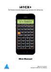
The 16C Digit Pad and 16C Keyboard Overlay.
Related to the quick entry modes, you can also use the 16C digit-pad to directly enter 1-9 single
digits as values. This is done from the 16C prompt, no need to call 16NPT at all – so even if its
applicability is limited to single-digit integers it doesn’t get any easier. Some typical uses for this
functionality include quick arithmetic (double, half, triple, etc.) and integer values used as parameters
for other functions. The picture below shows the 16C Keyboard Overlay in all its glory, where the
options for 16NPT, LOW16^ and the digit pad are shown in red color.
All functions shown on this overlay require pressing the 16C main launcher first.
Note: You can assign the 16C function to any location on the keyboard. Because it is used very
frequently it’s recommended you change that location from time to time to avoid the associated
hardware wear & tear on the key domes.
Always ensure that Revision “O1” or higher of the Library#4 is installed on the system.
(c) Martin-McClure
Page 16 of 63
September 2015
HP16C Emulator Module for the HP-41CX
2.3. Data Output – { SHOW , WINDOW }
When executed in manual mode (RUN), every function in the 16C Emulator module terminates the
execution by calling the data output routines - also directly available in function SHOW. This presents
the result value as a (possibly scrolling) string of digits in the ALPHA registers, preceded by the base
indicator on the left. For a more effective presentation SHOW will leave out the padding zero
characters to the left of the first significat digit, regardless of the selected word size.
This includes the 16C stack and memory handling function like 16X<>Y or 16RCL; so the user can
always expect to see a proper integer “digital” value as result of the operation.
This presentation will be omitted when the functions are executed in a program, with the exception of
SHOW itself which will put the result in ALPHA and stop the program if the user flag 21 is set - as it
is the case for the native function AVIEW.
Another possible option to visualize the value in the 16X register is the function WINDOW. Like in the
original 16C, it presents the value across a variable number of 8-character windows, as many as
needed to cover the actual length of the value. For instance in binary base with a word size of 56 it
may take up to 7 windows to review the complete result (maybe less since here too padding zeros on
the left won’t be shown).
Contrary to the original 16C however the listing starts with the MSB in window 0 (the first one), and
this will always be shown when you call the function. The succesive characters will be placed in the
following windows – until the LSB is placed in window 6 for the example mentioned above.
The user can navigate sequentially through the windows pressing the + and - keys, or randomly
get into any specific window by presing its corresponding number (from 0 to 7) on the number pad.
You’ll then use the back arrow key to leave the show, so to speak.
The windows are numbered from “W0:” to “W7:” placed at the left of the LCD. The selected base
character is also shown the the right of the LCD in all cases .
When used in a program, WINDOW will take the argument# from the next program line as a nonmerged design – similar to other prompting functions like 16STO and 16RCL.
The True Meaning of GRAD revealed.
If you always thought that it stood for a so-called centesimal angular mode seldom-used (except by
surveyors we’re told) then you’re in for a nice revelation ;-)
GRAD really stands for “GReater than Alpha Display” - The GRAD annunciator will be lit when the
value to display exceeds the 24-character limit of the ALPHA registers, as a visual clue that you need
to use WINDOW to see the complete value.
This will only occur in binary base mode, with word sizes larger than 24 bits, and when the significant
bits exceed that number (remember the leading zeroes won’t be shown). Every other case is wellserved by SHOW using the ALPHA register - even if it is exercising its scrolling capacity.
(c) Martin-McClure
Page 17 of 63
September 2015
HP16C Emulator Module for the HP-41CX
Let’s see an example using a large word size (say ws=56). Enter the decimal value 1234567789, and
show it in binary using the WINDOW function screens:
Exceute BINM (this sets GRAD), and WINDOW. Then use the hot keys to access all the relevant
screens as follows: - Note the storage order of the bits, with the MSB in the leftmost position of W0
and the LSB at the rightmost position of W3
Therefore the binary bit stream is as follows:
B: 1 001 001 100 101 100 000 001 001 101 101
Summary of Data formats used throughout the registers.
Data is stored in different formats depending on the registers they are in.
-
The lower bits registers in the standard stack are stored in BCD (Binary-Coded Decimal)
format, thus you can see them like regular decimal values if you exit the displayed prompt
from the 16NPT output (say for instance pressing the back arrow).
-
The higher bits registers in the 16C buffer are stored in binary format, i.e. Non-normalized
numbers or NNN’s. Realize that for any math operation the lower-bits first will be converted to
binary, and only then the operation will be applied.
-
The visual representation in the “Window” buffer registers is stored as character digits in
ASCII code. It may take up to 64 characters; therefore there are 8 “Window” registers like in
the original 16C machine. Realize that whilst the ALPHA register is the repository for SHOW,
the information shown in the WINDOW screens uses the LCD as a vehicle instead.
(c) Martin-McClure
Page 18 of 63
September 2015
HP16C Emulator Module for the HP-41CX
3. 1.- Differences from the original 16C.
The obvious differences are the dedicated hardware - like the keyboard layout and the LCD. These
account for the most dramatic changes in utilization, since on the 41 the 16C Emulator is just one of
the many other modules that can be used simultaneously, and it needs to co-exist with the 41 native
OS.
But far from being a disadvantage that makes it much more interesting, as you benefit from the
power and capability offered on the 41 like extendend capacity in data registers and program space,
larger LCD with automatic scrolling functionality, and of course the ability to compbine the 16C
functions with any other from the 41 OS at the same time.
Is it a better 16C than the original 16C? Well that depends on your previous experience and bias – so
if you live and breathe by the original machine this module will make you do things a little different –
but if you’re just a casual user or start anew the 16C Emulator module on the 41 is a much more
convenient tool, with a more sophisticated user interface and rounder function set - not lacking any
functionality from the original machine.
Automated Base Conversions: the four modes.
There are five base modes on the 16C Emulator: Binary, Octal, Decimal, Hexadecimal and Floating
Point. By default the floating point mode is pre-selected upon initialization, i.e. the first time the
calculator is started with the 16C Module plugged in. There will be no value displayed while the
machine is in FLOAT mode.
The number conversion between the different bases is performed automatically as you select the base
mode of choice. There is therefore no need to exceute any function for visualization – just change to
the base of choice using one of the four base mode functions: BINM, OCTM, DECM, and HEXM.
These are located in the top row on the 16C keyboard, assigned to the [B], [C], [D], and [E]
respectivelly.
Note: Another way to change the base mode is using the MOD launcher – which will be described
later in this section.
The display always shows the base digit on the left, so you can tell which based it is expressed on.
Note that the values in the 16C stach will not change when you modify the base mode: they are in
binary and BCD as explained before, and the value display routine will represent them in the
appropriate base as per the current selection.
These three numbers are indeed very different from
each other – the base identifier gives them away.
Don’t forget to change the default mode to a digital
base; no display will occur in FLOAT mode.
(c) Martin-McClure
Page 19 of 63
September 2015
HP16C Emulator Module for the HP-41CX
3.1.1. Number Entry on the 16C Stack.
By default the 41 keyboard knows nothing about the 16C module. The standard functions are always
available for real-number operation (call it the FLOAT mode if you wish). This is important to
remember, as it imposes some discipline on the user to differentiate them from the 16C-version of the
same functions – for instance for number entry and stack handling.
For example, pressing “1234” , ENTER^ pushes the real number 1,234 into the Y-register but it does
nothing good to the 16C stack at all – just the opposite!
For a proper 16C value entry you must use 16NPT at all times – even in its quick-entry and shortcut
modes. Thus the right keystroke sequence will be: 16NPT, “1234”, ENTER^.
Not much more elaborate, as it only requires the 16NPT as a prefix. This function will lift the 16C
stack automatically so no need for a final 16ENT^ at the end in this example.
Similarly other stack manipulation and memory exchanges need to use the 16C-versions instead of the
“native” standard ones. Here is where the 16C keyboard comes to the rescue, as it has most of
them pre-assigned to their logical positions (like 16STO in the STO key, 16RDN in the RDN key,
etc). All you need to remember is always press the 16C launcher key first, then the 16C function to
complete the action.
Using the 16C launcher is a more convenient method than populating the 41 keyboard with multiple
standard key-assignments for three reasons:
-
It doesn’t prevent the standard functions from being available in USER mode
It allows direct access to both main functions and sub-functions equally
It doesn’t take extra memory registers to hold all those many key assignments
However if those points are not an issue you can always re-configure the entire 41C keyboard using
ASN to map the main functions (won’t work for sub-functions) as you find it more appropriate.
Entering lower-bit values with LOW16^
As an alternative to 16NPT you can also use sub-funtion LOW16^ for a quick-entry mode of values
in the lower-bits half-register. With this method you enter the number directly in the X-register
instead of the ALPHA registers to hold the characters.
Obviously this only allows introducing digits 0-9 since the standard X- stack register is used. Besides
that, the value entered will be normalized to the base and word size conditions in effect by the
function, so that the end result will comply with the status of the machine.
Examples.: with word size = 16 and HEX mode selected
12345, 16$ “LOW16^” =>
1234,
LASTF
=>
“H: 3039”
“H: 4D2”
But with word size ws=8 and BIN mode selected instead:
12345, 16$ “LOW16^” =>
“b: 111001” , which corresponds to 57 in decimal – i.e. the value has
been truncated to 8 bits
Note: pressing the “digit-pad” in program mode (16C plus number key) is the best shortcut to enter
LOW16^ in program mode; just make sure the number is already input in the previous program line.
(c) Martin-McClure
Page 20 of 63
September 2015
HP16C Emulator Module for the HP-41CX
3.1.2. Flags as Mode Semaphores.
Personally I always thought that one of the shortcomings on the original machine is that it offers no
visual information for the currently selected signed mode. Whether it is unsigned, 1’s or 2’s
complement there’s no indication on the display to help you interpret the results – which believe me,
there will be differences depending on the current setting. As a consequence I need to use the
STATUS function very frequently just to see the mode, not very efficient in my mind.
On the 16C Emulator this is always shown by the first three user flag annunciators, “ 0”, “1”, and “2”.
At all times one of those three will be set to show you the current complement mode, where zero
means unsigned mode. They act as semaphores more than programming flags, and while you can
manually changed them using the 41 SF/CF functions it is strongly recommended you don’t do so.
Some functions rely on their status during intermediate calculations, and besides they’ll be changed
back by the 16C Emulator at the first opportunity to syncronize with the complement mode set.
In other words, flags 0,1, and 2 are reserved as they are taken over by the 16C Emulator in ther role
of signed/unsiged mode semaphores.
The example below shows the decimal representation of H: 9000 in 1CMP and 2CMP modes for a
word wsize of 16 bits. Can you tell at a glance which one is which?
Carry and Out of Range flags. (CY & OOR)
The original machine uses flags 4 and 5 for the Carry and Out of Range conditions respectively. The
display shows “C” for Carry set and “G” for OOR set, which therefore are matched to flag 4 and 5.
On the 16C module however the flags used are 3 for Carry and 4 for OOR – obviously those are also
shown in the annunciators area of the 41 display so they were the logical choice. As to why carry is 3
and not 4 as in the original machine, well we went with the rhyme as opposed to the reason this time.
CY and OOR will be set and cleared during the execution of numerous functions, summarized on the
table below. In general the CY management is identical to the original machine but the Emulator
applies a more extensive rule for OOR, in that there are additional instances besides the math
functions that also modify OOR. This prevents confusing interpretations of “why is OOR set now” as a
left-over from several operations before.
In other words the OOR flag is triggered more frequently on the emulator than it is on the original
machine, like for instance when recalling a number from memory using 16RCL or another 16C stack
function (16RDN or similar), in the event that the value being placed in the 16X register is too large
for the current word size – i.e. the ws had changed since that number was first stored in the other
register.
Note: For more on the CY and OOR flags, you should also refer to the Diagnostics section for
flashing messages on Carry and Out-of-Range conditions, user-selectable in a configurable optional
mode.
The table in next page summarizes all functions impacting the status of CY and OOR flags:
(c) Martin-McClure
Page 21 of 63
September 2015
HP16C Emulator Module for the HP-41CX
Function
16+, 1616*
16/
16SQRT
16X^2
16CHS, 16ABS
DBL*
DBL/
SL(N), SR(N), ASR
RL(N), RR(N),
RLC(N), RRC(N)
16X<>Y, 16X<>,
16RCL, LST16X
16RDN, 16RUP
CL16X, CL16ST
16WSZ
Carry
yes
no
yes
yes
no
no
no
yes
yes
yes
yes
no
no
no
no
no
Out of Range
yes
yes
yes
no
yes
yes
cleared
cleared
no
no
no
yes
yes
yes
cleared
yes
Remarks
|Result| > |max(ws)|
Result > max(ws) => OOR
RMD#0, => CY
RMD#0, => CY
Uses 16Y and 16X regs
*very* CMP-dependent
y * x -> (X & Y)
(y & z) / x -> X; RMD#0 => CY
may push msb/lsb => CY
may push msb/lsb => CY
may push msb/lsb => CY
16X > max(ws) => OOR
16X > max(ws) => OOR
16X > max(ws) => OOR
16X > max(ws) => OOR
Table 3.1. Functions affecting the status of CY and OOR flags.
Blue font functions denotes additional OOR conditions beyond the original 16C machine.
SLN and SRN are new additions in the emulator. They behave like the rotation counterparts
and only set/clear CY on the last position shifting.
max(ws) is the maximum value that can be represented within the selected ws, max(ms) =
2^ws -1. See appendix A1 for a complete table, and sub-function WSMAX for their calculated
values.
No Leading Zeros flag. { LDZER }
Since flag 3 is reserved for Carry that means the “Leading Zeros” functionality from the 16C is not
available on the emulator in the same way – zeros are always omitted by default as it was described
in the data input & ouptut sections of this manual. Space is at a premium on both ALPHA and the
LCD so it didn’t seem to be a good idea to use it with non-relevant zeros. The only logical and needed
exception is during the digit input process in 16NPT, which allows for the first digit to be a zero.
You can however use the subfunction LDZER to shows the value in 16X including the leading zeros;
as a function of the base and the word size. Like it is the case in the original machine this functionality
is not available in Decimal mode (where the actual number of digits depends on the entered values).
It is also somewhat limited by the maximum length of the ALPHA registers, so it’s not recommended
you use it for long binary values (all other cases will fit).
Examples: show the leading zeros for the OCT value 13 with ws=13, then changed to HEX:
(c) Martin-McClure
Page 22 of 63
September 2015
HP16C Emulator Module for the HP-41CX
3.3.3. What’s the Status?
The STATUS function is meant to show the current configuration of the emulator settings. Like in
the original machine the display includes the complement mode and the word size, but contrary to it
the flags information is replaced with the currently selected base. This should not be a shortcoming
considering that the status of the relevant system flags 0-4 is always shown in the annunciators
section of the LCD display, thus they are visible at all times.
Taking advantage of the alphanumeric capabilities the complement mode is shown as “0c”, “1c”, or
“2c”. Likewise the selected base is spelled out as mnemonic (BIN, DEC, OCT, HEX, or FLT). The text
is right justified and will stay in the display for a short while before the current value in the 16X
register is shown again.
The examples above both show the machine recently had both Carry (user flag 3) and Out-of-Range
(user flag 4) conditions. You can see that the complement mode matches the status of flags 0-1-2.
Flashing Functions.
Some functions will flash the result for a while and then revert to showing the current value in the 16C
register. For STATUS this is also the case on the original 16C, and like on it you can hold the flashing
display by holding any key - after you have allowed it to be presented, or otherwise all you’ll get is
the “NULL” message from the 41 OS.
Besides STATUS the other flashing functions are #BITS, WSFIT and 16WSZ? – the last two being
new additions to the function set, which will be described later on.
New (Flashing) Error Conditions.
The Division functions may show the error conditions to denote a math error condition – either a
division by zero in 16/ or a quotient result too large for the selected word size in DBL/
These error messages will briefly show in the display, but the original arguments will remain in the
16C stack. If this occurs during a program the execution will halt showing the familiar “DATA ERROR”
message.
(c) Martin-McClure
Page 23 of 63
September 2015
HP16C Emulator Module for the HP-41CX
3.1.4. Prompting Functions.
The HP-41 features a user interface design more advanced than what the original 16C has. One of the
nicer features is the prompting functions, whereby the function’s argument is entered at the prompt in
manual mode.
Whenever possible we have favored this implementation over the usage of the 16X register for
function parameter, saving so keystrokes and simplifying the data entry sequence – as this approach
removes the need to use the 16C keypad or 16NPT to enter the parameters.
This is only applicable to the operation in manual (RUN) mode. In Program mode the functions
behave in the same way they do on the original 16C machine.
The new prompting functions are shown in the table below:
Function
Parameter
Function
Parameter
MASKL _ _
MASKR _ _
Sb _ _
Cb _ _
b? _ _
SLN _ _
SRN _ _
1
1
0
0
0
1
1
RRN _ _
RRCN _ _
RLN _ _
RLCN _ _
16WSZE _ _
WINDOW _
1 to ws
1 to ws+1
1 to ws
1 to ws+1
0< ws <65
0<= w# < 8
to
to
to
to
to
to
to
ws
ws
ws-1
ws-1
ws-1
ws
ws
Common implementation features to all these functions are as follows:
-
Parameter entry requires two digits, always assumed to be decimal numbers irrespective of
the selected base mode. You can use the “soft” keys on the two top rows for parameters 1 to
10.
-
The prompts will stay put (i.e. the function will ignore the input) for parameters larger than
the maximum word size (64).
-
A warning message reminding of the current word size “WS= nn” will be shown if the
parameter entered is larger – In a running program the message shown will be ‘OUT OF
RANGE’ in those instances, and the execution will halt at the current program line.
-
Entering “00” will toggle between complementary function pairs, i.e. change MASKL into
MASKR, RRN into RRCN, RLN into RLCN, SLN into SRN, and vice-versa. This does not impact
the bit selection functions Cb, Sb, and b? – for which zero is a valid input value.
-
Pressing [SHIFT] will activate the INDirect facility – i.e. the parameter is retrieved from the
standard data register entered at the prompt. No support for STack registers is provided, so
do not use IND ST_ even if you can bring that option to the display.
-
When you enter the functions in a program the prompt will be discarded by the OS – so you
can fill it with any values.
-
In a running program the parameters are taken from the 16X register –the same as in the
original machine. Just fill the prompt with any values when you enter the function – they’ll be
ignored by the OS at that point. Note that in program mode a zero or values larger than the
current word size will also trigger an out of range condition.
(c) Martin-McClure
Page 24 of 63
September 2015
HP16C Emulator Module for the HP-41CX
3.1.5. Test Functions Launchers.
You may have noticed the conspicuous absence of the test conditional functions from the 16C overlay
– or almost, since there above the EEX key are to be found the two test launchers, X?Y and X?0 –
very much following the design used by other calculators, like the HP-32S.
All individual test functions are in the auxiliary FAT, thus they’re implemented as sub-functions. In fact
that’s also the case for the X?0 launcher itself – even if that fact is totally transparent to the user and
on the overlay.
There are six different tests for XY conditions, plus another six for zero conditions. Each group is split
into two screens, with three choices on each of them as shown in the pictures below. You can use the
[SHIFT] key to move between the screen choices within each launcher, and the “anchor” key to
change the launcher type back and forth:
And pressing the “anchor” key [A] changes to the zero-test groups:
In all cases the selection is made using the top row keys [C], [D], and [E] – You can also hit the
“anchor” key [A] to toggle between the X?Y and X?0 launchers right from within them !
Being subfunctions adds no restriction to the testing functionality, even if an index line number is
required in a program to identify which one is to be used. As it is known, the non-merged functions
cannot be located *after* a test conditional (or otherwise the skip-if-false rule will jump into the
middle of both lines) – but there’s nothing preventing them to be placed *before* a normal program
line. The non-merged functions take care of updating the program counter to always ignore the
index# line, so the YES/NO, do-if-true rule is perfectly applicable in this case.
Examples:
a.
01
02
03
04
Correct utilization
16#
6
GTO 01
GTO 02
b.
01
02
03
03
04
Incorrect utilization
FS? 25
16#
6
GTO 01
GTO 02
That’s the reason why the tests have all six cases, including “>=”, which wouldn’t be possible to do
using a chained double conditional like it is done for the standard OS functions.
The table below shows the sub-function indexes (in decimal) used for the test conditionals:
Test Criteria
=
#
>
>=
<
<=
(c) Martin-McClure
X vs. 0
6
7
8
9
10
11
Page 25 of 63
X vs. Y
12
13
14
15
16
17
September 2015
HP16C Emulator Module for the HP-41CX
3.1.6. ISZ/DSZ and Function Parameters.
The HP-41 has its own implementation of the index-controlled functions ISG and DSE, more flexible
than those in the HP-16C and HP-15C – which use the HP-67 model with ISZ and DSZ instead,
whereby a unique indirect register is used and the index value is always made with zero.
For convenience the emulator includes DSZ and ISZ, which use the R00 register to hold the “indirect”
variable “I “. Therefore you won’t need to worry about converting the format for 16C program
compatibility using ISG and DSE. Notice however that this implementation still uses a standard
register (R00) and not a 64-bit logical register like it is the case for the 16C stack or the other
registers as accessed by 16STO and 16RCL.
While it is safe to assume that loop counters and other parameters won’t exceed the 32-bit limit, you
can always “convert” the index into a 64-bit format using LOW16^ in case that is required.
Similarly, the parameter for 16WSZE can only go up to 64 so it’s a bit of an overkill to allocate 64 bits
for that one too; therefore you can just use a standard value in X and 16WSZ will accept it as a valid
input. Remember however not to disturb the 16C stack by doing so!.
Contrary to this situation, the masking, bit shifting and rotation functions expect 16C-formatted values
when used in a program for the number of positions (or number of bits in the MASKL/R case) – thus
you shouldn’t use the standard X-reg workaround with them. As a reminder, the three proper ways to
do it are:
-
a string value in ALPHA plus 16NPT (and optionally 16APN), or
a decimal value in real-stack X register plus LOW16^, or
a value from 16RCL, 16X<>, or any other 16C stack operation.
Registers and Word Size changes.
There is no effect of a word size change in the data stored in the data registers. This is different from
the real 16C machine, which adjusts the values in memory to fit the currently selected word size –
spilling over adjacent registers in case of a wordsize decrease and splitting across registers in case of
a wordsize increase.
Put in another words, the size of the storage registers in the HP-41 is fixed, always 56 bits whereas on
the 16C it is a variable number defined by the smallest multiple of 4 bits (half-bytes) equal to or
greater than the current word size.
Depending on your programs and needs that may be a fundamental difference or just a negligible
detail – but nevertheless it is important to be aware of if for the cases where this becomes a relevant
consideration. Suffice it to say that the memory allocation is a very particular affair on the 16C, much
more intricate than on any other HP calculator to say the least.
(c) Martin-McClure
Page 26 of 63
September 2015
HP16C Emulator Module for the HP-41CX
3.1.7. Square Root and Square Power. { 16SQRT , 16X^2 }
The Square root function is a bit of a hybrid in that is uses the native OS routines to calculate the
result. This is clearly a way-around approach that works just fine for input values lower than 2^33 but
that needs to be adjusted for larger values of the input parameter.
The adjustment is done in a short FOCAL code stub triggered by the function itself when required. It
simply checks if the square power of the result matches the input parameter. If it does then it’s a
perfect square that needs no adjustment. If it doesn’t then it may need subtracting one to the result,
and it will always have to set carry.
The only caveat to this approach is that the original input value is not left in the LST16X register – but
in the 16Y level of the 16C stack. In any case the final result will only be shown in manual mode, not
if the function is executed in a program
The program below illustrates the method used for the adjustment of the result calculated by the
16SQRT function. The actual implementation is more clever and splits the execution between an intial
MCODE part and a final FOCAL adjustment only done when needed.
1
2
3
4
5
6
7
8
9
10
11
12
13
14
15
16
17
18
19
20
21
22
23
24
25
LBL "64SQRT"
CF 05
CF 06
32SQRT
LOW16^
LST16X
16RDN
16*
16RUP
16X#Y?
SF 05
16X>Y?
SF 06
LST16X
FC? 05
GTO 05
FS? 06
GTO 06
1
LBL 06
SF 03
LBL 05
SHOW
END
32-bit square root
replicate result in 16C stack
recall input x
place it in 16T level
calculates sqrt(x)^2
recall x to 16X
is x # sqr(x)^2?
yes, set flag 5
is x > sqr(x)^2?
yes, set flag 6
recall sqrt(x) to 16X
were they different?
no, the result was ok
was it greater?
no, skip adjustment
yes, subtract one
(always < 2^32)
sets carry
show result
done.
The square power 16X^2 is a subfunction available for keytroke convenience, as it is assigned to the
X^2 key on the 16C keyboard. It uses the main 16* code with 16Y equal to 16X, thus it is completely
equivlent to the sequence { 16ENT^, 16* }. There is no byte savings in a program using either of
those approaches- 4 bytes will be used.
Therefore you need to keep in mind that two levels of the 16C stack will be used. Note that following
the standard conventions the input parameter is left in the LST16X register.
(c) Martin-McClure
Page 27 of 63
September 2015
HP16C Emulator Module for the HP-41CX
3.1.8. A few Examples: Gray Code, Bit Extraction, Add w/ Carry
The following examples are taken from the HP-16C article published in the May 1983 HP-Journal
issue. With them you should get familiar with the way the emulator functions are used to prepare
16C-like programs on your HP-41. We’re sure you’ll appreciate having the function names shown as
opposed to their keycodes on the original machine - and enjoy seeing the goose flying.
a. Binary-to-Gray and Gray-to-Binary conversions
1
2
3
4
5
6
LBL "GRAY"
16ENT^
SR
XOR
SHOW
RTN
7
8
9
10
11
12
13
14
15
16
17
Note that the test function 16X#0?
Really corresponds to the combination of
the two program lines:
LBL "BIN"
16ENT^
LBL 02
SR
XOR
LAST16
16X#0?
GTO 02
16RDN
SHOW
RTN
16# and
7
Example: convert b: 11010 to Gray code and back to binary.
Keystrokes
BINM
16NPT, 1, 1, 0,1,0, R/S
XEQ “GRAY”
XEQ ”BIN”
Result
b: xxxxx
b: 11010
b: 10111
b: 11010
Comment
current 16X content
enters binary value in 16X
Gray equivalent
Original value back
b. Bit Extraction and Addition with Carry
1
2
3
4
5
6
7
8
9
10
11
12
13
14
LBL "bXT"
16RDN
RRN
16RUP
LAST16X
16"1"
16NPT
16+
MASKR
AND
HEXM
SHOW
RTN
1
2
3
4
5
6
7
8
9
10
11
12
13
14
Note the usage of 16NPT to enter values
to the 16C register, as shown in lines
7/8 of “bXT” and lines 3/4 of “16+C”.
LBL "16+C"
CF 03
"0"
16NPT
RLC
16+
CF 05
FS? 03
SF 05
16+
FS? 05
SF 03
SHOW
RTN
Note also the carry flag is “3” on the
emulator, not “4” as in the original
machine.
Apart from that the programs are
practically identical to the original ones
on the real 16C machine.
Examples: Extract bits 2-5 from the value H: 39 (or b: 111001)
Keystrokes
HEXM
16NPT, 3, 9, R/S
16C, 2
16C, 5
XEQ “bXT”
(c) Martin-McClure
Result
H: XXXX
H: 39
H: 2
H: 5
H: E
Comment
current 16X contents
enters 39 in 16X
lifts 16C stack
lists 16C stack
or b: 1110
Page 28 of 63
September 2015
HP16C Emulator Module for the HP-41CX
3.2.- New functions not present on the original 16C.
This section needs to start describing the other function launchers – one of the more relevant
additions to the functionality of the emulator not available in the real 16C machine.
There are two kinds of launchers: those that group functions by complementary operation (like ROT
and SHF), and those that do it according to a functional criteria, (such as MODBIT,LEFT and
RGHT). Note the consistent use of the sigma letter in their names to denote a launcher funtion.
3.2.1. Rotations Launcher – { ROT }
This launcher groups the 8 rotation functions into two screens, one for operation excluding the Carry
bit and another for the operation including it. Once it is up on the display you will use the [SHIFT] key
to toggle between each screen, as shown below:
Where the only visible clues are the SHIFT annunciator and the “C” added to the screen id# on the
left. The function table is below:
RL
RLN _ _
RRN _ _
RR
Rotate
Rotate
Rotate
Rotate
Left
Left n positions
Right n positions
Right
RLC
RLCN _ _
RRCN _ _
RRC
Rotate Left thru CY
RLC n positions
RRC n positions
Rotate Right thru CY
3.2.2. Shiftings Launcher – { SHF }
This launcher groups 4 bit shifting functions in the first screen, plus another 4 bit-manipulation
functions in the second. Once it is up on the display you will use the [SHIFT] key to toggle between
each screen, as shown below:
SL
LN _ _
RN _ _
SR
Shift
Shift
Shift
Shift
Left
Left n positions
Right n positions
Right
DGLJ
LJY
RJY
ASR
Digit Left Justify
Left Justify
Right Justify
Arithmetic Shift Right
Remarks:
-
Both the Rotations and the Shifting launchers expect you to choose the option using the top
row keys [B] to [E] as per the screen layout.
-
Hitting the “anchor” key [A] (in the non-shifted screen) will move back and forth between
these two launchers, the Rotation and the Shifting screens.
-
Pressing the back arrow keys cancels the function and displays the current value in the 16C
register again.
(c) Martin-McClure
Page 29 of 63
September 2015
HP16C Emulator Module for the HP-41CX
3.2.3. System Modes Launchers – { MOD and BIT }
Moving on now to the “functional criteria” launchers, they have in common that the prompt includes
the different choices as a string of letters separated by colons, and the selection is made using the
initial letter of the function chosen.
The first two group the signed modes, the base modes, and other system configuration controls –
very fundamental part of the system indeed. MOD is assigned to the USER key on the 16C
keyboard, and shows the following teo screen when called – toggled with the [SHIFT] key as usual:
Unshifted screen.
Roughly speaking the left half of the LCD is for the base modes (Binary, Octal, Decimal, Hex and
Floating Point Mode) whereas the right half of the LCD is for the signed mode (UCMP, 1CMP and
2CMP) plus the word size setting (16WSZE, 16WSZ?). The question mark is for STATUS.
BINM
OCTM
DECM
HEXM
FLOAT
-
Binary Display
Octal Display
Decimal Display
Hexadecimal display
Floating Point mode
Separator - shows ©
MOD
UCMP (0)
1CMP
2CMP
16WSZE _ _
16WSZ?
STATUS (?)
Unsigned Mode
1’s Complement mode
2’s Comlpement mode
Sets word size
Shows Current ws
Shows the Status
Shifted sscreen:
Here too the left part is for general configuration and information functions, whilst the right part
includes bit and digit reversal and sums - plus the three general bit manipulation functions.
BASE?
16KEYS
TS/L
LDZER
DGRV
Recalls current base
16C key assignments
Toggle Silent/Loud
Shows Leading Zeros
Separator - shows ©
Digit Reversal
BIT
REV
DGD
#BIT
Cb _ _
Sb _ _
b? _ _
Bit reversal
Decimal Digit Sum
#Bits set (*)
Clears bit
Sets bit
Is bit set?
(*) Use the “H” character for the hash/pound symbol - #
One of the main advantages of these launchers is that they provide direct access to both main and
sub-functions in their choices. You should also note that the functions 16# and 16$ are also included
in the choices even if not shown in the LCD – just by pressing the USER and ALPHA keys as well.
So there you have it, perhaps a bit of repetition but you have it both ways so no excuse for not being
able to access the functions or subfunctions in a split second anymore.
(c) Martin-McClure
Page 30 of 63
September 2015
HP16C Emulator Module for the HP-41CX
3.2.4. Left and Right Launchers – { LEFT and RGHT }
The last two group many shifting and rotation functions together using the geometric position as a
criteria – as opposed to the specifit bit manipulation action as in the previous cases. You can think of
these two launchers as the two personalities of the same function, and as you surely have guessed
already you’ll use the [SHIFT] key to toggle between them at will.
There are 9 functions on each screen, as shown on the function tables below:
LEFT _
LJY
REV
MASKL
SLN
RL
RLN
RLC
RLC#
STATUS (?)
Left Justify
Reverse Bits
Mask Left
Shift Left n-positions
Rotate Left
Rotate Left n-positions
Rotate Left thru CY
RLC n-positions
Shows the Status
RJY
ASR
MASKR _ _
SRN
RR
RRN
RRC
RRC#
STATUS (?)
RGHT _
Right Justify
Arithmetic Shift Right
Mask Right
Shift Right n-positions
Rotate Right
Rotate Right n-positions
Rotate Right thru CY
RRC n-positions (*)
Shows the Status
(*) Use the “H” character for the hash/pound symbol - #
LEFT is a main function but RGHT is located in the Auxiliary FAT, with index# = 2
Note also that the main four launchers are interconnected and can be navigated sequentially using the
XEQ key. Refer to the chart in next page for a complete representation of the options.
Launchers as sub-functions.
There are four launcher functions located in the auxiliary FAT, thus implemented as sub-functions in
the 16C Emulator module: SHF, BIT, RGHT, and X?0.
Because sub-functions are always programmable (i.e. cannot be declared as non-programmable),
when you execute them in program mode the function itself will be entered into the program. This
means you cannot use them this way in program mode to directly access their menu choices as it
happens in manual mode.
To work-around this limitation you can use their “parallel” launchers - which as main functions are
properly declared as non-programmable - and toggle their functionallity using either the SHIFT key
and/or the anchor key [A], as follows:
Use
Use
Use
Use
X?Y, [SHIFT]
LEFT, [SHIFT]
ROT, [A], [SHIFT]
MOD, [SHIFT]
->
->
->
->
for
for
for
for
X?0 options
RGHT options
SHF options
BIT options
Naturally you can also access any of their menu choices by calling them individually, using its index or
name within the auxiliary FAT – as described in the next pages.
(c) Martin-McClure
Page 31 of 63
September 2015
HP16C Emulator Module for the HP-41CX
3.2.5 Launcher Maps – Navigating the Function Shortcuts
A picture is worth ten-thousand words…
(c) Martin-McClure
Page 32 of 63
September 2015
HP16C Emulator Module for the HP-41CX
3.3. Remaining functions not on Launchers.
As there are several other functions not included into any launcher, one would assume that there
must be some other way to access them. After all they can also be very useful either in manual mode
or included in your program, and who knows, some of them can even become your very next favorite
one.
Those amongst you familiar with the SandMath or PowerCL modules would already know the answer
is in the sub-function execute functions, which for the 16C Emulator are 16# and 16$.
There are three ways to execute any sub-function:
-
by name, spelling all letters at the “16$ _” prompt – For your convenience the ALPHA mode
is activated by 16$ so you can start spelling the function directly, saving another pressing of
the ALPHA key – (like it is needed for COPY for example).
-
by its index, entering the number at the “16#_ _ _” prompt (in decimal) - the subfunction
name is briefly shown in the display when it is entered using its index at this prompt , as well
as during a single-step execution in a program. This provides visual feedback to the user as to
whether the function was that intended to use.
-
by direct enumeration using FCAT, hitting XEQ when the sub-function name is shown and
the enumeration is paused (single-stepped).
In terms of the 16C keyboard, you can access 16# pressing PRGM and 16$ pressing ALPHA keys
respectively at the 16C prompt (and some other launchers as well) – all conveniently layed out for
you.
Note: Even if the sigma character “” can be typed during the 16$ prompt, it however won’t be
recognized by the name search routines due to some conflicts in the character value assignment. You
need to use the “N” character instead – or the 16# function followed by the sub-function index. This
only impacts the sub-function DGD and the three sub-function launchers covered before.
(c) Martin-McClure
Page 33 of 63
September 2015
HP16C Emulator Module for the HP-41CX
3.3.1. Last Function functionallity and Programability.
Also common to the other modules (not surprisingly since the same routines in the Library#4 are
used), the function is either executed in manual mode, or automagically entered as two program
lines in PROGRAM mode. Furthermore the subfunction code is stored in the LastFunction buffer so it
can be re-executed pressing LASTF on the 16C keyboard (Radix key at the 16C_ prompt).
Note that 16$ can also be used to execute functions in the main FAT, or even functions located in
other plug-in modules: if the function name is not found in the auxiliary FAT the search continues
automatically through all the modules plugged on the 41 system; and only if no match is found the
‘NONEXISTENT’ error message is displayed.
Obviously there’s a noticeable time penalty associated with all this - but one that it’s totally
unpercieved on the 41-CL set in TURBO 10 or higher in case you wonder.
LASTF Operating Instructions
The Last Function feature is triggered by pressing the radix key (decimal point - the same key used by
LastX) while the launcher prompt is up. This is consistently implemented across all launchers
supporting the functionality in all four modules – they all work the same way.
When this feature is invoked, it first shows “LASTF” briefly in the display, quickly followed by the lastfunction name. Keeping the key depressed for a while shows “NULL” and cancels the action. In RUN
mode the function is executed, and in PRGM mode it’s added as two program steps if programmable,
or directly executed if not programmable.
If no last-function yet exists, the error message “NO LASTF” is shown. If the buffer #9 is not present,
the error message is “NO BUF” instead.
The LastF buffer is maintained automatically by the modules (created if not present when the
calculator is switched ON), and its contents are preserved while it is turned off (during “deep sleep”).
No user interaction is required.
The buffer reserves one register for each of the four modules that have sub-functions, plus the header
also stores the 41Z last-function - which is always in its main FAT. Therefore up to five last-functions
can be simultaneously available at any given time. A total of five registers are used, as follows:
Register
b4
b3
b2
b1
b0
Used for:
SandMatrix fcn id#
SandMath fcn id#
PowerCL fcn id#
16C Emulator – Time-based Seed (RND)
Header – w/41Z fcn id#
Not bad for a single-line, 12-chars LCD machine from 1979, won’t you agree? Which once again
proves the adagio “it’s not the size of the wand what matters but the skill of the wizard who uses it…”
(c) Martin-McClure
Page 34 of 63
September 2015
HP16C Emulator Module for the HP-41CX
3.4.- Individual Description of the new functions.
The remaining sections provide a succint description of the added functions not included in the
original 16C calculator and not covered already in previous chapters of this manual. Some are little
embellishments of standard 16C functions, or natural extensions of the same ideas that probably
weren’t included in the original machine due to space constraints. They are located in the auxiliary
FAT and therefore you need to use the 16# or 16$ launchers to execute them.
3.4.1 Negative Logic Functions. { NAND , NOR , and XNOR }
Not needing much as description, these three round up the set of logical functions and save you from
having to NOT the result of their positive counterparts.
Examples. Here’s a table of direct results with ws=32 and 16x=1, 16Y=0
Value
Unsigned
1CMP
2CPM
NAND
d: 4294967295
d: -0
d: -1
NOR
d: 4294967294
d: -1
d: -2
XNOR
d: 4294967294
d: -1
d: -2
3.4.2. New Word Size related functions. – { WSFIT , WSMAX , 16WSZ? }
16WSZ? is a flashing function that in manual mode shows the current word size briefly on
the display, and then enters that value in the 16X register - peforming a stack lift. You can
maintain the flashed message up holding any key once it has been shown – or it’ll just NULL
itself out.
WSMAX simply returns to the real X-register the maximum value that can be represented
with the currently selected word size. In math terms, this is calculated by the formula:
Wsmax = [e^(ws*Ln 2)] – 1
WSFIT will change the selected word size to the needed number of bits to represent the
current value in the 16X register. This has two possible uses, one to downsize the word size in
case the value in 16X is smaller than the maximum one (i.e. eliminating thos bits used by the
leading zeroes), but another one is to increase its size as per the binary value exisiting in the
16X register – which in some instances may be a superset of its visual representation made
by SHOW and WINDOW.
Example. With ws=32 calculate the square of H: 123456.
16NPT “123456”, 16X^2 returns H: 66CB0CE4 and sets the OOR flag.
Pressing WSFIT shows the message “WS=41” followed by H: 14B66CB0CE4
(c) Martin-McClure
Page 35 of 63
September 2015
HP16C Emulator Module for the HP-41CX
3.4.3. Bit Reversal function – { REV }
Often it’s needed to reverse the bit sequence of a word – be that because of incompatible data
transfer protocol conventions or for another legit reason. This is no surprisingly the subject of applied
math and sophisticated algorithms exist – but this implementation follows a sequential alteration of
the bits to build a mirror-image of the initial word.
Note that the reversion is made on the complete word size, i.e. taking into account the leading-zeros
as well. There are two ways to circumvent that if not desired:
1. Execute WSFIT first to adjust the word size to the number of relevant bits, then call REV.
Realize that the word size has been changed and may need changing back.
2. Call REV and then use RJY on the result to get rid of those reversed leading zeros after
they’re reversed into the LSB positions.
Example: set ws = 12, HEX mode. Get the bit reversal of 9
16NPT, 9,
REV
RJY
=> H: 9 (or b: 00001001 )
=> H: 90 (or b: 10010000 )
=> H: 9 since 0x9 is a “polindrome” value, so to speak
Example: Verify that the bit reversal of 0xD9 with a word size ws=8 is 0x9B
Which is easy enough to check in binary base, but pretty challenging in decimal with 2’s complement
set, as a manner of example:
3.4.4. Right and Left Justification. - { LJY , RLY }
There is no Right Justify function on the original 16C but somehow it felt just natural to include that
function to complete the set, if only for symmetry sake. But there’s also some slight difference in the
way LJY the Left Justify function works.
The 16C Emulator versions return the left- and right-justified values to the 16X register, and the
number of positions needed to do the justification in the 16Y register – exactly opposite to the original
LJ function on the machine.
Not much of a difference, as executing 16X<>Y will bring things back to the original shape – but
nevertheless important for you to be aware of in case you’re using programs copied from the original
machine.
(c) Martin-McClure
Page 36 of 63
September 2015
HP16C Emulator Module for the HP-41CX
3.4.5. Shifting multiple Positions – { SLN , SRN }
The original 16C includes one-position shifting functions SL and SR, which on the emulator have been
moved to the Auxiliary FAT as subfunctions. Their place in the main FAT has been taken by n-position
versions of the same functiions, which as a particular case can also perform the single-position. With
n=1.
The number of positions is entered in the function prompt in manual mode, or taken from the 16X
register when running a program.
In a program any value larger than the current word size or zero will result in a “DATA ERROR”
condition, but in manual mode:
Entering a number larger than 64 will be ignored and the prompt will stay put.
Entering a number larger then the word size will show the message “WS=nn” and cancel.
Entering zero at the prompt will toggle between these two functions.
Obviously right-shifting more positions than the current number of bits will result in a zero result. Not
so obvious perhaps is the case of left-shifting a number of positions beyond the current word size,
which will eventually also result in zero once all bits have been moved off the field.
Notice that when shifting multiple positions the carry flag will reflect the circumstances on the last bit
shiting action, and thus not a cumulative effect. This is consistent with the behavior of the n-position
rotation functions RLN and RRN.
Bacause the shifted bits are “lost”, these two functions are not always complementary of one another.
This is different from the bit rotation functions, where the rotated bits are kept within the word and/or
CY bit – just in different positions.
Note that when entered in a program it is more byte-efficent to use the n-positions version with the
value “1” in the 16X register (three bytes) instead of using the 16# launcher followed by its subfuction index (four bytes). The 16C stack conditions however are different in those two cases, so you
should choose the better one for your case.
(c) Martin-McClure
Page 37 of 63
September 2015
HP16C Emulator Module for the HP-41CX
3.4.6. Storing the 16C Stack in Extended Memory. { SAVE16 , GET16 }
You can use sub-functions SAVE16 and GET16 to store and retrieve the complete 16C stack plus the
auxiliary buffer registers to / from an extended memory file. Note that even if you can have multiple
X-Mem files with different 16C stack sets (obviously with different file names), there can only be one
on-line at any time.
When you execute GET16 there’s a check prompting for confirmation. Realize that this action will
override the existing 16C buffer, replacing it with the data from the X-Mem file. Only the “Y/N” keys
are active at this prompt.
Upon termination the function will show the current value in the 16X registers in RUN (manual) mode;
either the current one for SAVE16 or the newly retrieved one in the GET16 case. Also the mode
annunciators 0-1-2 will be changed appropriately if different.
If you’re using the OS/X extension module you’ll notice that these files will be identified with the
character “H” during the CAT_4 enumeration. Also note that 16C stack files are always 25 registers
long – 20 for the buffer plus 5 for the {X,Y,Z,T,L} stack.
Notice how the X-Mem file really occupies 28
register in X-Mem, as there are three
additional registers needed by the OS to
manage it within the X-Mem file system.
The file header register is the second one
starting from the bottom. This address can
be retrieved using the function FLHD,
available in RAMPAGE module amongst
others.
The buffer address can be obtained using
function BUFHD, available in the RAMPAGE
module as well – with several others for
buffer management in case you’re interested.
3
(c) Martin-McClure
Page 38 of 63
September 2015
HP16C Emulator Module for the HP-41CX
4.0 Silent and Loud Modes. { TS/L }
Without a doubt the Carry and Out of Range flags are a vital component of the information displayed
during the execution of the calculations. However it’s not difficult to miss a particular occurrence of
these situations, or you may find yourself paying extra attention just to catch possible changes of
these flags.
The 16C Emulator offers a “training wheels” mode to make those situations easier to remark: each
time the Carry or Out of Range flags are set a corresponding message is shown briefly in the display.
Besides the visual message also a short tone sounds to alert the user, with a higher pitch for CY and a
lower one for OOR.
Note that contrary to the standard 41-OS these messages will flash in the LCD briefly and then they’ll
go away to show the result of the function executed. We have used the text “OVERFLOW” for the Out
of Range warning as it is easier to read during the brief flashing time, and to differentiate it from the
floating point error from the native 41 OS. We’ll refer to this as the OOR event nonetheless, following
the 16C conventions.
Activating the LOUD mode.
The SILENT/LOUD modes are user-selectable executing the sub-function TS/L to toggle the active
mode. Of course you can also use the numeric launcher 16#, with index =054. When you do the
mode selected is also briefly shown in the display – plus a dual tone if you’re toggling to LOUD mode.
The CY/OOR messages “air time” will be variable, as it depends on the subsequent operations
performed during the execution of the function. For 41CL users the implementation is compatible with
the current turbo setting so you won’t be missing them even if the CPU is running at high speeds.
Independently form whether you are a casual user or a seasoned digital design engineer, you may
find this functionality useful, neutral, or plain hideous – in which case all you need to do is ignore this
section altogether as the factory-default setting is SILENT mode. Go ahead and try it out to get the
feeling and decide for yourself.
It comes without saying that the flags annunciators will continue to be displayed as well in Loud
mode. Lastly, and as you can expect, the messages will not be displayed when the functions are
executed in a runnng program.
(c) Martin-McClure
Page 39 of 63
September 2015
HP16C Emulator Module for the HP-41CX
4. 1.- An alternative to the 16C keyboard. { 16KEYS }
If you prefer a more direct approach to access the 16C Emulator functions in an automated way, the
sub-function 16KEYS will prepare a standard key assignment-based complete keyboard re-definition
for all those (main) funcions from the 16C keyboard to be assigned to their corresponding keys.
When executed it prompts for the action to perform, press “Y/N” either to do the assignments or to
clear them. You can also cancel at this point pressign the back arrow key. Once the action is
completed the function will display the current value in 16X.
,
or:
This method removes the need to press the 16C “prefix” key each time you need to execute the
emulator functions, thus from that perspective is a faster one and perhaps the closest to the original
machine. The only requirement is to have USER mode on, and conversely you’ll need to turn it OFF
when you need to access any of the standard HP-41 functions. Another disadvantage is that no other
key assignments are compatible with this mode since all keys have a function assigned.
It however has two important shortcomings:
No support for the LASTF facility or the 16# and 16$ launchers – since it’s not possible to
assign functions to the PRGM, USER or ALPHA keys. Note that you can also use the “16C_STACK” function – or XROM 16,49 – to trigger the LASTF functionality. It’s easy to do
with the XROM function in the OS/X module. Also to overcome this deficiency the 16#
function will be assigned to the [RADIX] key.
No support for sub-functions from the auxiliary FAT - which have been replaced with 16C
itself, so you have a way to invoke them: simple repeat the same action, which the second
time will trigger the 16C-variant on that sequence of keystrokes.
Remember that executing a function directly via XEQ (or assigned to a key) does not store the
function’s id# in the LASTF buffer – so even if you can access the LASTF functionallity the buffer
contents will only be updated when you use 16C or other launcher to execute the function.
Both the 16C-prefix Keyboard and the 16KEYS approach use the same 16C overlay shown in page 15
of this manual. Since both are available on the emulator you can choose the one that suits you better
- the choice is yours.
(c) Martin-McClure
Page 40 of 63
September 2015
HP16C Emulator Module for the HP-41CX
4. 2.- A few development aids.
The remaining section of the manual describes a handful of utility functions that were using during the
development of the module for testing purposes. Some may be of interest to you if you feel
adventurous and decide to explore the 16C Buffer or other more technical aspect of the
implementation.
4.2.1. FX Buffer registers handling. { A2FX , CLRFX , EX2FX , FX2EX , FXSZ? }
As the repository of the digits shown in the displaying of the results, the buffer FX registers have a
pivotal role in the emulator design. Normally you won’t have to worry about their contents – which
will be updated by the module’s functions and accessed by SHOW and WINDOW; but should you
feel intrigued here are the functions available for the tasks.Note that the output of these functions is does not utilize the module’s digital facility, but just
standard real numbers or even no changes to the display at all.
A2FX – Alpha to FX Registers
This function writes the current content of the ALPHA registers {M, N, O, P} into the buffer FX
registers, starting at the first available position within the FX set (as per the [S&X] field
information). Up to 24 characters can be written using this function, but there is no action on
the GRAD annunciator in case of overload.
CLRFX – Clears FX registers.
A complete clear of all eight FX registers, which resets their “active” contents to zero. Register
labels will be respected, from F0 to F7 in nybbles <13,12>.
EX2FX and FX2EX – Moving data between EX and FX registers.
This pair of functions move the data back and forth between the {E0, E1} registers (in binary
form – NNN) and the {F0 – F7} registers. The ASCII digit values in FX are dependent on the
current base mode selected.
Note that even afer executing FX2EX the result will *not* be placed in the 16C stack – that is
the buffer register b13 and stack X-register.
FXSZ? – FX Registers size.
This function returns the number of digits currenly used in the FX registers. A maximum of 64
digits is returned (for BIN mode only), sinc each FX register can hold up to eight characters.
The status of the GRAD annunciator will be lit if greater than 24. In fact this function is like
ALENG for ALPHA, but excluding the base id# and leading blank character.
The result will be pushed in the 16C stack,
and brefly shown in a flashing message:
Advanced user’s tip: Nothing like a comprehensive RAM editor like RAMED in the OS/X module for
cursory inspections of all the buffer registers in all their g(l)ory details – even editable if you decide to
take a walk on the wild side…
(c) Martin-McClure
Page 41 of 63
September 2015
HP16C Emulator Module for the HP-41CX
4.2.2. Buffer Creation and Data Types. { CHKBB , L<>H , L-H , H=L }
CHKBB – Check (and create) Buffer.
Seminal routine accessed by *every* single one of the module functions: use it to create the
16C Data buffer when needed – as it is done automatically during the CALC_ON event (polling
point).
L<>H – Swap Lower and Higher bits.
You can use this function to swap the low and high bits parts of the 16X register. In other
words, the contents of the stack- X and buffer b13 registers will be exchanged, doing the
required conversions as appropriate: b13 = BIN(X), and X = BCD(b13).
Example: using a word size of 56, enter the hex value 12300000000000
Type: 16NPT, “123”, L<>H => H:12300000000000
If you execute it again you’ll get the original “123” input, i.e. the digits will be shifted down.
H=L and L-H – Copy and Move Lower bits
These two complement the swapping functionality, and provide ways to copy and move the
lower bits art of the 16X register into the higher bits. In both cases the previous content of
b13 will be overwritten, and in the move case (L-H) the X register will be cleared after the
copy.
A pre-requisite for these functions is that the current word size needs to to be larger than 32
in order for the higher bits register to be shown during the masking process. If this is not the
case the rerror message “WS=nn” will be shown (or “DATA ERROR” in a program execution).
The schematic below graphically shows the actions performed by these three functions:
4.2.3. Doubling and Halving the 16X value. { 2MLT , 2DIV }
2DIV and 2MLT
Handy shortcuts to divide or multiply the contents of the 16X register by two. It saves bytes in
a program and keystrokes during manual mode. It does not lift the 16C stack but saves the
original number in LST16X. Note however that the CY and OOR flags are not always set by
these functions.
(c) Martin-McClure
Page 42 of 63
September 2015
HP16C Emulator Module for the HP-41CX
4.2.4. Digit Justification, Reversal and Decimal Sum. { DGLJ , DGRV , DGD }
These functions can be considered an extension of the bit-based conterparts, LJY, REV, and #BITS.
The concepts are analogous to the original set, but these are digit-based instead of bit-based. The
results may be sometimes similar or even the same, but in general thay are totally different.
DGLJ does a digit-based left justification of the value in 16X, which in general is not the same
as the bit-based function LJY available in the main FAT (and in the original 16C). Only when
the bit density of the leftmost character (i.e. the number of bits per character) is complete
then both functions will yield the same result.
Example: with ws=32, left-justify the value H: 123 using bits and digits as criteria:
, vs:
DGRV does a full-digit reversal (i.e. mirror image) based on the information contained in the
ALPHA register. This should normally be based on the actual value in 16X, and therefore it’ll
return a digit-reversed version of the number. The result will be normalized to fit within the
current ws and complement mode selected. The original value is saved in 16L, the last-16C
register.
Note that contrary to the bit-reversal situation, the result here is completely base-dependent.
Also note that Zero chars on the left (after reversion) will ultimately be ignored. Obviously this
function is completely equivalent to REV for binary mode, since in that case each bit
corresponds to one digit as well.
Examples: with ws=32, any complement mode:
DGRV
but say now you have ws=8
DGRV
DGD does a decimal digit sum based on the bcd values from 16X – independently from the
base mode set. The decimal result is briefly shown as a flashing message in the display, and
then it is input in the 16X level (in the configured based) replacing the original value – which
goes to the 16L register as well.
, then:
(Note: remember that the sigma character in a sub-function name cannot be directly entered via
the “” key (SHIFT-F) in ALPHA mode; thus you need to use the ‘N” character i.e. for ”‘NDGT”
instead.)
(c) Martin-McClure
Page 43 of 63
September 2015
HP16C Emulator Module for the HP-41CX
4.2.5. Test for Maximum Negative (signed) Value. { MNV? }
MNV? is a test function to check whether the number in 16X is the Maximum Negative signed
Value (MNV) for the currently selected word size. The result will be YES/NO, skipping a
program line if false – as with any standard tests.
Of all the conventions used on the 16C calculator one of the trickiest to grasp is that of the maximum
negative value for signed complements. Even if the definition is clear enough, some of the particular
function results when the operand is such a maximum negative value may be unexpected or even
disconcerting to the untrained eye – and it accounts for many numerous singularities in the general
algorithms to properly emulate the real machine.
For starters, this is the only value that equals its own 16CHS in 2CMP – This is not the only
remarkable thing about it, but remember this one, we’ll use it later on.
We define the maximum negative value as the largest absolute number with a negative sign - i.e. the
msb is set in either 1CMP or 2CMP. Given the arrangment of the negative values (see appendix 1B)
the maximum negative happens to be that such all other bits are zero, and therefore can easily be
generated calling LJY on the number “1”; or creating a single bit MSKL ; or also doing a left-shifting
of (ws-1) number of bits with SLN.
Corner cases involving the MNV.
Setting ws=32, 2CMP, let’s do some math using the MNV(32) = H: 80000000 as one of the
arguments. (i.e. d: -2147483648)
Multiplying or dividing the MNV by -1 is perhaps an academic discussion but calculating the result
poses some challenges to the algorithms. The 16C responds the following in 2CMP:
Division:
Multiplication:
16NPT, “1”, LJY, 16NPT “0”, NOT, 16/ => H: 0, and OOR
16NPT, “1”, LJY, 16NPT “0”, NOT, 16* => H: 0, and OOR
Note that the last one yields a different result from a sign change of the MNV, i.e. both operations are
surprisingly not equivalent in this case.
Is that a picky behavior or is it justified? Mathematically speaking multiplying by -1 should be
equivalent to doing 16CHS, and for the MVN that results in the same MVN – not zero/OOR. But this is
not how it works here, where the rule for a sign change is “invert, then add one”, and not a
multiplication by -1 . Such is life in the digital world!
To Get
-1
-1
-1
-0
MNV
MNV
MaxVal
MaxVal
in Mode
2CMP only
1CMP only
Signed modes
1CMP only
Signed modes
Signed modes
Unsigned Mode
Signed modes
Argument
0
0
1
0
1
ws-1
0
1
w/ Operation
NOT
NOT
16CHS
NOT/16CHS
LJY
MASKL
NOT
LJY
and Arg.#2
w/ Op#2
1
16-
result
16CHS
In 1CMP: 0 – 1 = -1 /CY; adding 1 again returns -0 instead of the original 0.
(c) Martin-McClure
Page 44 of 63
September 2015
HP16C Emulator Module for the HP-41CX
4.2.6. Quick Dec <-> Hex conversions. { D>H , H>D }
These two functions perform a quick & dirty conversion between decimal and (unsigned) hex values
using the real X-register and ALPHA. Use then when you want to check results independently from the
selected base on the emulator.
The maximum number allowed is H: 2540BE3FF or d: 9,999,999,999 in decimal. Both functions are
mutually reversed, and H>D does (real) stack lift as well.
These functions were written by William Graham and published in PPCJ V12N6 p19, enhancing in turn
the initial versions first published by Derek Amos in PPCCJ V12N1 p3.
4.2.7. Recalling the current base value. { BASE? }
The function BASE? recalls the value of the current base to the 16X register – as an easy way
to find it out in a running program. The value is pushed into the 16C stack. Possible return
values (in decimal) are 2, 8, 10, and 16 – always shown as ”‘10” in their digital display.
This function is similar to 16WSZ? in that both return configuration data to 16X, and that in manual
mode an information message will also be displayed:
4.2.8. Alpha Reverse and Left append character. { X-LA , AREV }
The function X-AL appends the character which ASCII code is in X to the left side of the
ALPHA string. It is therefore the symmetrical of XTOA. This function was written by Håkan
Thörngren, and first published in PPCJ V13 N7 p9. It is used as a subroutine by the Leading
Zeros functionality, within the function LDZER.
The function AREV does a mirror-image of the ALPHA register contents. It was written by
Frans de Vries and first published in DF V10 N8 p8. It is used as an internal subroutine by the
Digit Reversal, within the function DGRV.
Copyright Message “Easter Egg” { (c) }
So you can amuse your friends, a copyright message with a fancy sound can be invoked using the (c)
function, with index# =060 in 16# - to access this message:
(c) Martin-McClure
Page 45 of 63
September 2015
HP16C Emulator Module for the HP-41CX
a.1
a.2
b.1
c.1
Maximum values as function of word size
The Hexadecimal Number system
Program Examples
Buffer Technical Details
Buffer Registers Explained
Input/Output Routines
Multiplication Routines
Division Routines
Addition/Subtraction Routines
(c) Martin-McClure
Page 46 of 63
44
45
48
51
September 2015
HP16C Emulator Module for the HP-41CX
Appendix A1. Maximum Values depending on the Word Size.
The table below shows the maximum possible values that can be represented as a function of the
selected word size. These values are also returned by the function WSMAX for the current selection
of ws (in floating point format, native to the 41C OS).
ws
1
2
3
4
5
6
7
8
9
10
11
12
13
14
15
16
17
18
19
20
21
22
23
24
25
26
27
28
29
30
31
32
ma x va l ue
1
3
7
15
31
63
127
255
511
1,023
2,047
4,095
8,191
16,383
32,767
65,535
131,071
262,143
524,287
1,048,575
2,097,151
4,194,303
8,388,607
16,777,215
33,554,431
67,108,863
134,217,727
268,435,455
536,870,911
1,073,741,823
2,147,483,647
4,294,967,295
ws
33
34
35
36
37
38
39
40
41
42
43
44
45
46
47
48
49
50
51
52
53
54
55
56
57
58
59
60
61
62
63
64
max value
8,589,934,591
17,179,869,183
34,359,738,367
68,719,476,735
137,438,953,471
274,877,906,943
549,755,813,887
1,099,511,627,775
2,199,023,255,551
4,398,046,511,103
8,796,093,022,207
17,592,186,044,415
35,184,372,088,831
70,368,744,177,663
140,737,488,355,327
281,474,976,710,655
562,949,953,421,311
1,125,899,906,842,620
2,251,799,813,685,250
4,503,599,627,370,490
9,007,199,254,740,990
18,014,398,509,481,983
36,028,797,018,963,967
72,057,594,037,927,935
144,115,188,075,855,871
288,230,376,151,711,743
576,460,752,303,423,487
1,152,921,504,606,846,975
2,305,843,009,213,693,951
4,611,686,018,427,387,903
9,223,372,036,854,775,807
18,446,744,073,709,551,615
Also shown in the graphic below using a logarithm scale:
(c) Martin-McClure
Page 47 of 63
September 2015
HP16C Emulator Module for the HP-41CX
Appendix A2. The Hexadecimal Number System
The base of this number system is 16(d). The numbers 0-9 as well as
the letters A to F are used to represent 11(d) to 15(d). The carry over
to the next place occurs at 16(d). The table below shows the
correspondence between binary, decimal and hexadecimal numbers
up to 15(d):
As you can see on the table, Hex numbers are the natural choice to
represent four binary digits (4 bits); therefore the hexadecimal
number system uses the 4 bits of a nibble in the full value range. Each
nibble can represent values from bin 0000 to 1111, of in hex from 0 to
F. This number system is often used in computer science.
Representation of negative Numbers
Hex
0
1
2
3
4
5
6
7
8
9
A
B
C
D
E
F
Binary
0000
0001
0010
0011
0100
0101
0110
0111
1000
1001
1010
1011
1100
1101
1110
1111
Decimal
0
1
2
3
4
5
6
7
8
9
10
11
12
13
14
15
When using a limited count of digits m to represent numbers, the
value range to the numbers to be represented n is 0 < n < 2^m,
meaning that the greatest number will be 2^m – 1. Note that no
negative numbers are included in this system of notation. To remove this deficiency, the concept of
“complement” is introduced.
The Complement (from a reference K)
The K-complement of a number x is defined as the difference from K of that number: Com(x) = K–x
for which k is fixed by the chosen complement. Since in the binary number system the usual values
of K are 2^m, and (2^m – 1), we usually speak of “one’s complement” or the “two’s complement” –
representing the difference from either the greatest number represented or the one after it. In
general, for any base system “b” there will be a “b” and a “b-1” complement – like the 9’s and 10’s
complement in the decimal system where b=10.
Distribution of ranges of values.
If there seems no reason yet for the existence of complement notation, remember that to this point
we haven’t dealt with negative numbers. We shall include these by adopting an arbitrary distribution
of value ranges in our number systems. For instance in the binary system, we’ll define a negative
number as one which most significant (leftmost) bit is set (has a value of 1). Arranging number
distributions and using complements change the ranges of values as follows:
No Complement
b-Complement
(b-1) Complement
0 < x <= (b^m – 1)
- b^(m-1) <= x <= b^(m-1) -1
- b^(m-1) -1 <= x <= b^(m-1) -1
Basically in the signed modes (with complement) we divide the original total value range b^m-1 in
two half sections, allocating one of them for negative numbers and the left over for positive.
(c) Martin-McClure
Page 48 of 63
September 2015
HP16C Emulator Module for the HP-41CX
Complement (Signed) Modes.
The transformation of decimal numbers represented in the binary system (and vice-versa) varies
with the signed mode used. The three modes are:
-
Unsigned mode (no complement, only positive numbers)
1’s complement mode
2’s complement mode
The 1’s Complement of a number is calculated by subtracting this number from the greatest
representable number in the chosen word size (number of bits). For instance, say the word size is 5
bits – then the 1’s complement of a number “a” is (11111 – a). The computer simply inverts all bits of
the original number, i.e. executes the logical function “NOT”. Through this segmentation of the initial
value range (arbitrary but specific), all negative numbers have their highmost bit set, which plays the
role of the minus sign. In the q’s complement mode the number of positive and negative numbers
represented are the same, i.e. even zero has two possible representations: +0 and –0, which in binary
would be 00000 and 11111 (always assuming a word size of 5 bits).
The 2’s Complement of a number is calculated by adding one to its 1’s Complement. Using the
same example of word size 5 bits, the 2’s Complement of a number “a” would be (11111 – a) + 1,
The 2’s complement of bin 10001 is the number bin 01111. Notice how also in this segmentation the
leftmost bit is set for all negative numbers, and therefore takes over the role of the minus sign. In the
2’s complement mode there is one more negative number than in the positive number range, since
zero only has the representation +0
The Unsigned Mode (no complement). Since the Complement mode employs one bit as the
negative sign, the range of values for a word size of 8 bits in the 1’s complement is from –127 (d) to
+127(d), and in the 2’s complement from –128(d) to +127(d). Note that in both cases those are 256
values. For cases when only the positive number range is needed, the precedence sign bit is not
necessary (unsigned mode) and the value range is used for all cases from 0 to 255(d) - assuming the
same word size of 8 bits.
In the table below you can see the correspondence between the three sign modes for decimal
numbers 0-15 represented in binary, using a four-bit word size:
Dec
0
1
2
3
4
5
6
7
8
9
10
11
12
13
14
15
(c) Martin-McClure
Hex
0
1
2
3
4
5
6
7
8
9
A
B
C
D
E
F
Binary
0000
0001
0010
0011
0100
0101
0110
0111
1000
1001
1010
1011
1100
1101
1110
1111
Unsigned
0
1
2
3
4
5
6
7
8
9
10
11
12
13
14
15
1’s Compl.
0
1
2
3
4
5
6
7
-7
-6
-5
-4
-3
-2
-1
-0
Page 49 of 63
2’s Compl.
0
1
2
3
4
5
6
7
-8
-7
-6
-5
-4
-3
-2
-1
September 2015
HP16C Emulator Module for the HP-41CX
Appendix B1.- Programming Examples.
Let’s see an example of how the 16C Emulator module functions are used in a program. We’ll use the
Checksum Calculation example from the 16C manual, pages 90, 91 and 92.
The program assumes you have pre-loaded 4-bit hex values in registers R1 to R10, as follows:
R01:
R02:
A
7
R03:
R04:
B
1
R05:
R06:
3
D
R07:
R08:
A
2
R09:
R10:
D
6
The table below shows both the original program and the equivalent using the Emulator functions for
a side-to-side comparison; not surprisingly very similar in concept but with some differences –
especially in the 16C stack management.
Remarks:
hp-16c Progra m
1
LBL D
2
UNSIGN
3
4
4
WSIZE
5
HEX
6
"A"
7
STO I
8
0
9
ENTER^
10
LBL 0
11
RCL (I)
12
B#
13
+
14
X<>Y
15
0
16
RLC
17
+
18
X<>Y
19
DSZ
20
GTO 0
21
RTN
16C Emul a tor Code
1
LBL "CHKS"
2
UCMP
3
4
4
16WSZ
5
HEXM
6
10
7
STO 00
8
CLX16
9
16ENT^
10
LBL 00
11
16RCL
12
128
13
#BITS
14
16+
15
16X<>Y
16
0
17
16LOW^
18
RLC
19
16+
20
16X<>Y
21
DSZ
22
GTO 00
23
SHOW
24
END
1. Indirect Register “I” corresponds to R00
2. RCL (i) uses the indirect capability of
16RCL, adding 128 to the 16C-register
number.
3. Note the non-merged arrangement in
lines 11 & 12 for 16RCL, with the rg# in
the next program line.
4. Note how the parameter for the word
size is in the 16X register – lines 3 & 4.
In fact here we use an insider’s trick
using just the real-X register (only valid
for 16WSZE!)
5. Sub-functions (in brown color) really use
the 16C# launcher followed by an index
number
6. Entering 16C values requires either
16NPT or LOW16^ for numbers below
32 bits. This is how zero was input in
lines 16 and 17.
7. DSZ operates on standard values – as an
index very much like ISG and DSE do.
8.
A final SHOW instruction has been
added to see the 16C result.
Note how all the stack lift and drop are performed in exactly the same way as in the original machine
– pretty much following the same rules as in all RPN designs.
(c) Martin-McClure
Page 50 of 63
September 2015
HP16C Emulator Module for the HP-41CX
Appendix B2.- Square Root using Newton’s Method
The program below is an alternate (and very slow!) way to calculate the square root of a number,
simply using an iterative approach following Newton’s method:
Finding
is the same as solving the equation:
Therefore, any general numerical root-finding algorithm can be used. Newton's method, for example,
reduces in this case to the so-called Babylonian method:
The program uses the initial estimation: x0 = 6 * log(S)
Data registers R01 and R02 are used to store the successive approximations, Xn.
Example: Calculate the square root of ABC,DEF,ABC,DEF
16NPT, ABCDEFABCDEF,
XEQ “64SQRT”
(c) Martin-McClure
=> H: ABCDEFABCDEF
=> H: D1B7FD
Page 51 of 63
September 2015
HP16C Emulator Module for the HP-41CX
Appendix B3.- Showing leading zeros – A FOCAL reprise.
The program below is a parallel version of the MCODE function available in the module – it basically
uses the same method so you can see how it’s been implemented; in particular is a good example of
the BASE? function.
As you can see all action happens in the ALPHA register – and therefore the usage of the standard XFunctions AROT, ALENG – and ABSP from the OS/X module as well. Not only this program requires
the data registers 16R00 to preserve the original value, but it should also be said it will fail in 1/2CMP
due to the incompatible usage of user flags 1 and 2.
(c) Martin-McClure
Page 52 of 63
September 2015
HP16C Emulator Module for the HP-41CX
Appendix C.- Data Buffer Technical Details.
This document is an attempt to descript the format of the B buffer used by the HP-16 MCODE
Emulator Module developed by Angel Martin and Greg McClure. The B buffer is used to allow full 64bit word size emulation (as implemented on the HP-16).
The buffer requires 20 free registers. Function CHKBB (check for buffer B) is used to check for, and
create if needed, buffer B. The format of the buffer (from highest absolute register to lowest absolute
register) is shown below, and individual sections will be discussed after.
F7
F6
F5
F4
F3
F2
F1
F0
E3
E2
E1
E0
14
13
12
11
10
01
00
BB
0bbbbbbbb
0bbbbbbbb
0bbbbbbbb
0bbbbbbbb
0bbbbbbbb
0bbbbbbbb
0bbbbbbbb
0bbbbbbbb
0aaaaaaaa
0aaaaaaaa
0aaaaaaaa
0aaaaaaaa
0llllllll
0xxxxxxxx
0yyyyyyyy
0zzzzzzzz
0tttttttt
0mmmmmmmm
0mmmmmmmm
14f000000
00l
00l
00l
00l
00l
00l
00l
n0l
000
000
000
000
000
000
000
000
000
0cd
0bb
xxx
Input / Output sub-buffers, the “Windows” of the
HP-16. It is used for input of digits (for bin,
oct, dec, and hex modes) by user, and for output
of results of function or view.
In bin mode, b=0 or 1; oct mode, 0<=b<=7;
dec mode, 0<=b<=9; hex mode, any hex digit.
These digits are store in reverse of display or input.
b=bcd digit, l=number of digits used, n=negative
Temporary calculation registers. E0 and E1 are used
several purposes, E2 and E3 are for double precision
functions DBL* and DBL/.
These are the upper 32 bits for the stack registers.
The HP-41 can only save 32 bits of info in its std
stack, these hold the other 32 bits of simulated regs.
m represents the mask based on word size. Wordsize is
stored in bb, c is complement’s mode, d is calc mode.
Header with buffer id#, buffer size, and loud mode flag.
BB buffer register (Header)
Let’s start with the BB buffer header. It is required to identify the buffer, and the HP-16 MCODE
Emulation module will refresh this header on power on (as all buffers are refreshed by the individual
modules that require their use). The 14 is the buffer size in hex (requires 20 registers). The “f” is the
Silent/Loud mode flag used for message displaying. Nothing more is stored in this header. (Note that
the S&X field is used by function BFCAT and therefore is reserved).
Buffer registers 00 and 01
The 00 and 01 register hold a calculated mask that will help in making decisions (carry status, out-ofbounds conditions, etc) on the status of arithmetic and logic functions. It is related to the word size
(bb) and is described below:
For word size <= 32: All 01 m fields will be 0, i.e. it will contain 01 000000000 0cd. The 00 m fields
will represent the bits allowed in values to be saved and used. Some examples are: 00 0FFFFFFFF
020 (for 32 bits), 00 00000FFFF 010 (for 16 bits), etc.
For word size > 32: All 00 m fields will be F, i.e. it will contain 00 0FFFFFFFF 0bb. The 01 m fields will
represent the upper bits allowed in values to be saved and used. Some examples are: 01 0FFFFFFFF
0cd (for 64 bits, where bb would be 40), 01 00000FFFF 0cd (for 48 bits, where bb would be 30).
(c) Martin-McClure
Page 53 of 63
September 2015
HP16C Emulator Module for the HP-41CX
The cd bits in buffer register 01 show the current complements mode, c, and binary mode, d. If c=0,
no complement mode is set, c=1 means 1’s complement is set, c=2 means 2’s complement is set.
These settings influence both display and calculation flag results. If d=0, floating point mode is set,
and the HP41 registers act as normal (no emulation is in effect). If d=1 then bin mode is in effect,
d=2 means oct mode, d=3 means dec mode, and d=4 means hex mode.
Buffer registers 10 thru 14
When bin, oct, dec, or oct mode is in effect and word size > 32, then these buffer registers contain
the upper bits (beyond the 32 stored in the standard stack). For example, if the HP-16 “X” register
should contain the hex value 1234 5678 9ABC DEF0, then buffer 13 will contain 13 012345678 000
and actual HP41 register X will contain the floating point value corresponding to 9ABCDEF0, that is,
2,596,069,104. This is done to insure the registers can always been viewed in floating (not have
weird Non-Normalized contents). The same pairing of a buffer register and a stack register exists for
each of the stack registers, thus emulating the HP-16 64-bit binary stack. The pairing is as follows:
Buffer register + HP41 stack register = HP-16 emulated register
b10
Binary(T)
16T
b11
Binary(Z)
16Z
b12
Binary(Y)
16Y
b13
Binary(X)
16X
b14
Binary(L)
16L
Buffer registers E0 thru E3
These buffer registers are scratch registers. They are used for holding partial results, for holding
the dividend when translating binary output to digital representation, and for construction of binary
values on user input. Their purpose changes based on the function being simulated. The masks of
buffers 00 and 01 are applied here to insure values are in range, and to determine the proper carry
and out-of-range flag settings. An example of their use for digit input and display output is show in
the discussion of the F0 thru F7 buffer registers. They can’t be counted on to hold any values of use
between functions, and can be overwritten by any function needing them.
Buffer registers F0 thru F7
These buffer registers hold the digit representations of the binary values input from the keyboard, or
the digit representations of the binary values to output to the display. Similar to the Q register on
entry of some kinds of alpha data, binary values are written in or read out in reverse order. For the
multiplication and division routines, some of these buffer registers are also used as scratch registers.
The input routine takes digits entered by the user and stuffs them into these registers from right to
left, starting at F0 and continuing to F7. The number of digits entered in a particular register is placed
as the rightmost digit of the buffer, and up to eight digits can be entered into positions 3 thru 10 of
each register. This allows up to 64 digits (max possible for binary value with max word size) to be
entered. As an example: in oct mode 1234 1234 5656 is entered by keyboard. The contents of buffer
registers F0 and F1 will contain:
F1 000006565 004
F0 043214321 n08
(c) Martin-McClure
Page 54 of 63
September 2015
HP16C Emulator Module for the HP-41CX
Notice that the digits are entered from right to left, starting at position 3 of each register until
finished. All other Fx buffer registers will contain 0 length and 0 bcd values. The negative indicator
would be 0, since octal values do not include a sign.
After input is completed, the bcd to bin translation routine would then create the binary
representation of this octal number and place these into the following Ex buffer registers:
E1 000000002 000
E0 09C29CDAE 000
representing binary 2 9C29 CDAE (in hex). The X register would receive decimal value of
9C29CDAE(hex) and buffer register 13 would receive the 2 (assuming word size >= 34).
The output routine will take a value placed in the EX buffer registers and translate them to digits in
the Fx buffer registers. Then control will be given to the display routines which will use these
registers as HP-16 Windows. For example, assume the binary value in E0/E1 buffer registers are:
E1 000000222 000
E0 033334444 000
The bin to bcd translation routine would then take these values and translate them to the Fx buffer
registers based on mode (bin, oct, dec, hex). It will first clear all Fx buffer registers, then for oct
mode, the following will be placed into the Fx buffer registers specified:
F1 000360124 006
F0 040121341 n08
which represents 42 1063 1431 2104 octal. Window 1 on HP-16 would hold 421063 and Window 0
would hold 14312104. Notice these values are read from right to left. Again, since this is octal, n is 0
to represent no sign.
Negative value flag for Decimal signed modes
The XS digit of the F0 register has a special function to denote that a negative value is to be
presented in the LCD when a signed decimal base mode is the selected one. When the value is not
zero it will direct the [SHOW] routine to add a minus sign before the value, for the familiar
representation convention. This is also controlled by the complement mode, and built in the [EX2FX]
code.
Functions buffer usage outlines
The following sections will show how the buffers are used in various math / logic / programming
functions. One of the first things that will be noticed is that in addition to the auxiliary E2 and E3
buffer registers, for more complex cases buffers F0 and F1 are here also used as temporary registers
for calculation purposes.
(c) Martin-McClure
Page 55 of 63
September 2015
HP16C Emulator Module for the HP-41CX
Input/Output Routines
Input of various values for calculation is accomplished via several possible routines mentioned in this
manual (16NPT, LOW16^, 16APN). At the core of these functions are the [FX2EX] and [EX2FX]
routines (which are also available as sub-functions) that move the results of input back and forth
between the FX registers and buffers E0 thru E2. The info in buffers F0 thru F7 are ASCII values.
The FX2EX function translates the ASCII codes in buffers F0 thru F7 into binary in buffers E0 and E1.
It relies on the mode set in buffer register b01 (BIN, OCT, DEC, HEX). For BIN, OCT, and HEX modes
this is easy. It takes the info from each ASCII code in the F0 thru F7 buffers and shifting it into buffer
E0 (overflow bumping into buffer E1). In decimal, a special multiply by 10 and add value routine is
required to perform the translation into binary (instead of shifting by 1 [BIN], 3 [OCT], or 4 [HEX]).
Every math or logic routine will use the info in buffers E1/E0 as the 16X argument. The result that
should be in the 16X argument at the end of the routine is placed into buffers E1/E0, and a routine is
called to move that into the 16X register and displayed. The internal routine E01OUT is used to do
this. The EX2FX routine is at the core of this process. The display functionality of E01OUT is
reproduced with the SHOW function.
EX2FX is the mirror of the FX2EX routine. It takes the info in E0 and E1 and translates it into
buffers F0 thru F7. Again it relies on the mode set in buffer 01 (BIN, OCT, DEC, HEX). For BIN, OCT,
and HEX modes this is straightforward, bits are shifted into the buffers and changed into ASCII codes.
For DEC mode, a special routine to divide by 10 also has to be implemented. The sign of the decimal
value has to be considered as well (it is the only mode we have to worry about the sign). As digits
are found, the contents of buffer F0 thru F7 are shifted, and a proper count is maintained for each
buffer. Buffer register F0 also contains the negative indicator if DEC mode and the value represents a
negative value (only occurs in 1’s or 2’s complement mode).
Similar to the previous one, there is also a sub function available to execute the internal routine for
diagnostic cases. It will assume the information is already in binary format in the EX registers to move
it up to the FX registers in ASCII form.
The hierarchical levels amongst the input registers are shown again in the figure below, with the
sequence of routines needed to move the data up and down the different stages:
16X<-{E0,E1}; [FX2EX] ; [A2FX]; 16NPT
16X->{E0,E1}; [EX2FX] ; [SHOW]
(c) Martin-McClure
Page 56 of 63
September 2015
HP16C Emulator Module for the HP-41CX
Multiplication routine
The multiplication routine covers both 16* and DBL* in one routine. When the code needs to be
specific, it uses an internal system flag (specifically system flag 5) to perform the unique code for the
specific function. The beginning of the routine is basically the same:
1) 16LastX is performed to save the value of buffer 13 and stack register X into buffer 14 and
stack register L. The binary value of Y and contents of buffer 12 (16* multiplier) are moved
to buffers E2 and E3. The binary value of X and buffer 13 (multiplicand) are already in E0
and
E1.
2) If in 1’s complement or 2’s complement mode, take the absolute value of both the
multiplicand and the multiplier, saving the state of the combined signs in one of the CPU
internal registers (G in case you’re curious).
3) The high order of the absolute values of the multiplicand and multiplier are saved back to
buffers 13 and 12, the low order bits are saved to buffers F0 and F1 respectively. Thus
multiplicand is now in buffers 13/F0, multiplier is now in buffers 12/F1.
4) Now a full cross multiply is performed (using 16 bits at a time, thus 16 total cross
multiplications) into buffers E0 (low order) thru E3 (high order); this is the core part of the
multiplication routine. This routine is explained later in this section.
5) Notwithstanding a lot of weird code that checks for overflow or carry flag conditions, the
routine then divides into single precision (16*) and double precision (DBL*) result sections.
Here are the two possible paths:
a) For SINGLE PRECISION, the result may need a sign change (1’s complement or 2’s
complement mode); then an extended stack drop is performed (including buffers 10 thru
12 dropping down to buffers 11 thru 13) and the contents of the result in buffers E1 and
the BCD expansion of E0 are placed into buffer 13 and stack register X respectively
b) For DOUBLE PRECISION, three steps are required:
1) The result needs to be shifted so that the proper bits are separated into E3/E2 for
high order and E1/E0 for low order (based on word size); both buffer register pairs
need to contain values within the word size required.
2) The routine first checks to see if it may need a sign change (1’s complement or 2’s
complement mode); this check changes the order of the result to buffer order
E1/E0/E3/E2 (from high order to low order).
3) The result in buffers E3 and the BCD expansion of E2 (low order) are placed into
buffer 12 and stack register Y respectively (since that is where the low order piece is
stored for DBL*) and buffers E1 and the BCD expansion of E0 (high order) are placed
into buffer 13 and stack register X respectively.
6) The multiplication routine returns via a routine that translates the values in buffers E0/E1 into
buffers F0 thru F7, and displays the result.
Some of the seemingly redundant moves of values are explained by the fact that the change sign
routine (described later) works on data in buffers E1 and E0. Routines exist for easy exchange of
buffers E1 and E0 with E3 and E2, and for taking buffer 13 and the binary of stack X and putting it
back into buffers E1 and E0. Taking advantage of these routines dictated these moves. Also note
that for DBL* no stack drop is required at the end, since the multiplicand and multiplier are replaced
with the double precision result.
(c) Martin-McClure
Page 57 of 63
September 2015
HP16C Emulator Module for the HP-41CX
The cross multiplication step is carried out by taking the multiplicand and multiplier and separating
them into 16 bit chunks. This is required because there is no multiply instruction for the internal chip
of the 41C. The actual multiply workhorse routine takes a 16 bit multiplier and 16 bit multiplier and
yields a 32 bit result. This result is then moved or summed into the required locations in buffers E0
thru E3. The multiplicand saved in buffers F0/13 and multiplier saved in buffers F1/12 can be
represented as hex digit groups as follows:
F0: aaaa bbbb
F1: eeee ffff
13: cccc dddd
12: gggg hhhh
The 16 cross multiplications are:
1) dddd x hhhh into buffer E0 (moved)
2) cccc x hhhh + dddd x gggg into low 16 bits of buffer E1 (moved) and high 16 bits of buffer E0
(summed)
3) bbbb x hhhh + cccc x gggg + dddd x ffff into buffer E1 (summed)
4) aaaa x hhhh + bbbb x gggg + cccc x ffff + dddd x eeee into low 16 bits of buffer E2 (moved)
and high 16 bits of buffer E1 (summed)
5) aaaa x gggg + bbbb x ffff + cccc x eeee into buffer E2 (summed)
6) aaaa x ffff + bbbb x eeee into low 16 bits of buffer E3 (moved) and high 16 bits of buffer E2
(summed)
7) and finally aaaa x eeee into buffer E3 (summed)
Thus 16 total cross multiplications are performed. The last section of the multiply core normalizes
buffers E0 thru E3 (handles carries from E0 to E1, E1 to E2, etc). Thus, when double multiply is
performed with the max word size of 64 bits, a full 128 bit result can be calculated.
Change Sign Routine
An important part of both the multiplication and division routines when working in 1’s complement or
2’s complement mode is the subroutine [CHSUB], also used in function 16CHS. It basically takes the
value in buffer E1/E0 and performs a 1’s complement or 2’s complement on it. Buffer E1 is then
copied to buffer 13 and the BCD of E0 is copied to stack register X.
Such a seemingly simple task has however its quirks as a result of the definition of a value’s
complement. The maximum negative signed value in particular is an interesting boundary that needed
to be single-cased for this routine to work correctly in 2CMP mode.
(c) Martin-McClure
Page 58 of 63
September 2015
HP16C Emulator Module for the HP-41CX
Division routine
The division routine actually covers 16/, RMD, DBL/, and DBLR in one routine. Whether a divisor
or remainder is required, division must still be performed. When the code needs to be specific, it uses
two internal system flags (specifically system flags 0 and 5) to perform the unique code for the
specific function.
Since there is no division instruction for the internal chip of the 41C, it was necessary to figure out
how to do division of values bigger than the max size of the 41C registers. This was accomplished by
the method of partial division. The core routine used takes a dividend and divisor up to 40 bits, and
the result yields both a quotient and remainder.
Partial division takes progressive high order pieces of the dividend and a shortened divisor (usually 20
to 24 bits) and uses the core routine to yield a partial quotient. The full divisor is multiplied by the
partial quotient and subtracted from the dividend. Occasionally this results in a negative value of the
remaining dividend, so the partial quotient is adjusted to allow a positive difference. The final
dividend after subtraction is used for the next partial division.
The length of the partial divisor and piece of dividend depends on the length of the full divisor. For
divisors less than up to 24 bits the full divisor is used and no multiply and subtraction adjustment is
required.
Here is the division process in detail. In actual code, the process is divided into multiple sections
based on divisor length, and whether single or double dividend length.
1) 16LastX is performed to save the value of buffer 13 and stack register X into buffer 14 and
stack register L.
2) For 16/ and RMD, the binary value of Y and contents of buffer 12 (dividend) are moved to
buffers E2 and E3. The binary value of X and buffer 13 (divisor) are already in E0 and E1.
3) For DBL/ and DBLR, the binary value of Y and contents of buffer 12 (high order dividend) are
moved to buffers F0 and F1. The binary value of Z and contents of buffer 11 (low order
dividend) are moved to buffers E2 and E3. The binary value of X and buffer 13 (divisor) are
already in E0 and E1.
4) For DBL/ and DBLR, the values in buffers F0 and F1 need to be shifted down into buffers E2
and E3 depending on word size. This allows the division process to basically be the same for
all word sizes.
5) If in 1’s complement or 2’s complement mode, take the absolute value of both the dividend
and the divisor, saving the state of the combined signs in one of the CPU internal registers (G
in case your curious). This process also involves using buffers F2 and F3.
6) The (partial) division process is performed until all of the dividend is used and a final
remainder is left in buffers E0 and E1.
7) Notwithstanding a lot of weird code that checks for overflow or carry flag conditions (carry
always indicates a remainder is left, no carry means no remainder), the high order quotient
and BCD conversion of the low order quotient is put into either buffer 12 and stack register Y
for 16/ and RMD, or buffer 11 and stack register Z for DBL/ and DBLR. If the remainder was
desired (RMD or DBLR) then buffers E1 and BCD conversion of buffer E0 replaces the
quotient.
8) If 1’s complement or 2’s complement, the proper change sign is performed.
(c) Martin-McClure
Page 59 of 63
September 2015
HP16C Emulator Module for the HP-41CX
9) For 16/ and RMD, one extended stack drop is performed (buffers 10 thru 12 are dropped to
buffers 11 thru 13 in addition to the standard stack drop). For DBL/ and DBLR, TWO extended
stack drops are performed. Thus the quotient or remainder is now in buffer 13 and stack
register X, as well as E1/E0.
10) The division routine returns via a routine that translates the values in buffers E0/E1 into
buffers F0 thru F7, and displays the result.
Addition/Subtraction Routines
Addition and subtraction may be much simpler functions, but the complication for these functions
comes from the complement modes and their influence on the carry flag status, overflow flag status,
and adjustment of the final answer. One routine handles both 16+ and 16-, it uses an internal
system flag (specifically system flag 9) to perform the unique code for the specific function. Here is
the addition/subtraction function in detail:
1) 16LastX is performed to save the value of buffer 13 and stack register X into buffer 14 and
stack register L.
2) The result of buffer 12 added/subtracted from buffer E1 replaces E1. The result of the binary
value of Y added/subtracted from buffer E0 replaces E0. Carry/borrow from E0 propagates to
E1, carry from E1 is left in E1.
3) If 1’s complement mode, a special internal flag (specifically flag 6) is set to show we may
have to bump the result.
4) A special carry and overflow flag set routine is called to determine which flags to set. This is
described in more detail below.
5) An extended stack drop is performed and buffer E1 replaces buffer 13, and BCD of buffer E0
replaces register X.
6) The addition/subtraction routine returns via a routine that translates the values in buffers
E0/E1 into buffers F0 thru F7, and displays the result.
The routine that handles carry and overflow (or out of range) flags uses the following algorithms:
Assume that w represents the word size in use (1 thru 64). Assume that the lowest bit of the result is
bit 0, thus the highest bit of the result is n (OV bit) and for 1’s complement and 2’s complement the
n-1th bit signifies positive or negative value (CY bit). Z = X+Y for addition, or X-Y for subtraction. So
we have three CY bits to consider, XCY, YCY, and ZCY, and one overflow bit, ZOV.
For no complement mode the carry and overflow bits are set identically, they represent the value of
the ZOV bit.
For 1’s complement mode if CY is set then the result is bumped (+1 for addition, -1 for subtraction)
For 1’s and 2’s complement modes the algorithms are:
a) Carry = ZCY
b) OOR = ((XCY xor YCY) and not (ZCY xor ZOV)) or (not (XCY xor YCY) and (ZCY xor ZOV))
(c) Martin-McClure
Page 60 of 63
September 2015
HP16C Emulator Module for the HP-41CX
Creating a Carry-Mask (“1” at the WS position)
This routine prepares a "1" mask located at the ws bit, in the E0/E1 register depending on the ws
value. The mask is stored in B, and the pointer to E0/E1 is left in C on exit. If the word size exceeds
32, the status of CPU F1 will be set as a marker for the following routines that the mask’s “1” bit is in
the bE1 register (higher bits) - or conversely, in the bE0 (lower bits) if CPU F1 is clear.
Two entry points exist, so CPU flag 7 controls whether the mask is also AND-ed with the original value
for a quicker execution of the job. If done, the result is then transferred to CPU F8 status – which will
be clear if zero or set if not zero. This also allows for faster branching points in the code downstream.
RLRR
RLRR
RLRR
RLRR
RLRR
MWSPOS
MWSPS*
This routine prepares a "1" mask
located at the ws bit, in the E0/E1
register depending on the ws value.
The mask is stored in B, and the
pointer to E0/E1 is left in C on exit.
RLRR
RLRR
RLRR
RLRR
RLRR
RLRR
RLRR
RLRR
RLRR
RLRR
RLRR
RLRR
RLRR
LOWERB
NXTBIT
MASKOK
WSRGPT
gets pointer to reg with ws bit
either E0 / E1 as per F1
RLRR
RLRR
RLRR
RLRR
RLRR
RLRR
this exits with CY status
transferred to F8 - so it'll be
possible to adjust later using
the C<>ST instruction
RLRR
RLRR
RLRR
RLRR
(c) Martin-McClure
A177
A178
A179
A17A
A17B
A17C
A17D
A17E
A17F
A180
A181
A182
A183
A184
A185
A186
A187
A188
A189
A18A
A18B
A18C
A18D
A18E
A18F
A190
A191
A192
A193
A194
A195
A196
A197
A198
A199
A19A
A19B
A19C
A19D
A19E
A19F
A1A0
A1A1
A1A2
A1A3
284
013
288
198
226
270
038
106
304
130
021
306
027
308
266
1C6
04E
23A
1A6
346
01B
1FA
3E3
0EE
198
106
130
008
30C
013
226
206
28C
3A0
270
104
038
19C
06E
08E
3B0
2EA
013
108
3E0
CLRF 7
JNC +02
SETF 7
C=M ALL
C=C+1 S&X
RAMSLCT
READATA
A=C S&X
CLRF 1
LDI S&X
CON: 33
?A<C S&X
JC +04
SETF 1
C=C-1 S&X
A=A-C S&X
C=0 ALL
C=C+1 M
A=A-1 S&X
?A#0 S&X
JNC +03
C=C+C M
JNC -04
C<>B ALL
C=M ALL
A=C S&X
LDI S&X
8 ABOVE HEADER
?FSET 1
JNC +02
C=C+1 S&X
C=C+A S&X
?FSET 7
?NC RTN
RAMSLCT
CLRF 8
READATA
PT= 11
A<>B ALL
B=A ALL
C=C AND A
?C#0 PT<JNC +02
SETF 8
RTN
Page 61 of 63
simple version
flag the AND action
buffer hea der
pointer to b00
s el ect b00
b00 contents
ws i n A[S&X]
a s s umes ws <33
low bits limit
i s m# < 33?
yes , -> [LOWERB]
flag higher bits case
"032"
count = (ws - 32)
bl a nk s l a te
put "0001" i n C<3> di gi t
decrea s e counter
exi t i f a l l done
s hi fts the "1" one bi t l eft
do next
mask Is "000.. 1.. 000"
buffer hea der
put i n A for ma th
location of bE0
hi gher bi ts ?
no, s ki p l i ne
location of bE1
poi nter to bE0 / bE1
a re we ma s ki ng?
no, return here.
s el ect bE0/bE1
a s s ume LSb i s a zero
rea d i ni tia l bE0/bE1
hot-field delimiter
ma s k to A
keep ma s k i n B
AND the mask
NO, s ki p proces s
yes, set F8 for later check
September 2015
HP16C Emulator Module for the HP-41CX
To be continued...
(c) Martin-McClure
Page 62 of 63
September 2015
HP16C Emulator Module for the HP-41CX
(c) Martin-McClure
Page 63 of 63
September 2015