1
Operation
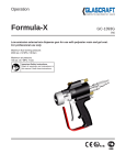
Indy
GC-1306T
EN
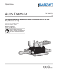
Internal-Mix Low Emission Dispense Gun
For use with Polyester Resin, and Gel-Coat. For professional use only.
Maximum fluid working pressure:
2000 psi (14 MPa, 138 bar)
Maximum air pressure:
100 psi (0.7 MPa, 7 bar)
Important Safety Instructions
Read all warnings and instructions in
this manual. Save these instructions.
II 2 G
Contents
Warnings........................................................... 3
Important Safety Information.......................... 5
Grounding......................................................... 6
Set-Up................................................................ 7
Parts.................................................................. 8
Pressure Relief Procedure............................ 14
Maintenance.................................................... 15
Accessories.................................................... 22
Technical Data................................................. 29
Graco Ohio Standard Warranty..................... 30
Graco Ohio Information................................. 30
2
GC-1306S
Warnings
The following warnings are for the setup, use, grounding, maintenance, and repair of this equipment.
The exclamation point symbol alerts you to a general warning and the hazard symbol refers to procedurespecific risk. Refer back to these warnings. Additional, product-specific warnings may be found throughout the
body of this manual where applicable.
• See Important Safety Information - MEKP, Polyester Resins and Gel-Coats and Spraying and Lamination
Operations section of this manual.
Changing Materials
Changing Materials
WARNING
•
When changing materials, flush the equipment multiple times
to ensure
it is thoroughly
clean.
FIRE
AND EXPLOSION
HAZARD
•
prevent
and
explosion:
Always clean
thefire
fluid
inlet
strainers after flushing.
Flammable fumes, such as solvent and paint fumes, in work area can ignite or explode. To help
•
•
•
• Use equipment only in well ventilated area.
• Eliminate
all ignition
sources; for
such
as pilot lights, cigarettes, portable electric lamps, and plastic
Check with
your material
manufacturer
chemical
drop
cloths
(potential
static
arc).
compatibility.
• Keep work area free of debris, including solvent, rags and gasoline.
• Do not plug or unplug power cords, or turn power or light switches on or off when flammable
Most materials
use ISO on the A side, but some use
fumes are present.
ISO on the
B
side.
• Ground all equipment in the work area. See Grounding instructions.
• Use only grounded hoses.
Epoxies•often
have
theofBgrounded
(hardener)
Hold
gunamines
firmly toon
side
pail when triggering into pail.
side. Polyureas
often
have sparking
amines on
the feel
B (resin)
• If there
is static
or you
a shock, stop operation immediately. Do not use
equipment until you identify and correct the problem.
side.
• Keep a working fire extinguisher in the work area.
PERSONAL PROTECTIVE EQUIPMENT
You must wear appropriate protective equipment when operating, servicing, or when in the
operating area of the equipment to help protect you from serious injury, including eye injury,
This section inhalation
is used with
somefumes,
RAM burns,
plates and
which
couldloss.
get pushed
out of the
drumsbut
of is
sealant.
of toxic
hearing
This equipment
includes
not limited to:
• Protective eyewear
• Clothing and respirator as recommended by the fluid and solvent manufacturer
• Gloves
• Hearing protection
Splatter Hazard
WARNING
TOXIC FLUID OR FUMES HAZARD
SPLATTER
Toxic fluids HAZARD
or fumes can cause serious injury or death if splashed in the eyes or on skin, inhaled, or
Hot
or toxic fluid can cause serious injury if splashed in the eyes or on skin. During blow off of platen,
swallowed.
• Read
MSDS’s
splatter
may
occur.to know the specific hazards of the fluids you are using.
Store
hazardous
in approved
containers,platen
and dispose
of it according to applicable
• • Use
minimum
airfluid
pressure
when removing
from drum.
•
guidelines.
Always wear impervious gloves when spraying or cleaning equipment.
Burn Hazard
For equipment used with heated material.
WARNING
GC-1306S
BURN HAZARD - Hot Surfaces
3
Skin Injection Hazard
Use with high pressure equipment, generally equipment with pressure rating of 900 psi or higher. There
sions of this section. 1) manual guns, 2) UL-1450 compliant equipment 3) automatic guns,/dispense val
tion valves, 4) heated hoses. Since the text contains mostly “Do not” statements, the symbols have lines
them.
Warnings
WARNING
WARNING
SKIN
HAZARD
SKININJECTION
INJECTION
HAZARD - Basic
High-pressure fluid from gun, hose leaks, or ruptured components will pierce skin. This may look
High-pressure
fluid from gun, hose leaks, or ruptured components will pierce skin. This may l
like just a cut, but it is a serious injury that can result in amputation. Get immediate surgical
a
cut,
but
it
is
a
serious injury that can result in amputation. Get immediate surgical treatm
treatment.
point
gun
at anyone
at of
any
•• DoDo
notnot
point
gun at
anyone
or at anyorpart
thepart
body.of the body.
•• DoDo
notnot
put put
youryour
hand hand
over the
dispense
outlet. tip.
over
the spray
•• DoDo
notnot
stopstop
or deflect
leaks with
yourwith
hand,
body,
glove,body,
or rag.glove, or rag.
or deflect
leaks
your
hand,
•• Engage
trigger
lock
when not
Do not
spray
without
tipspraying.
guard and trigger guard installed.
•• Follow
Pressure
Relief
Procedure
in spraying.
this manual, when you stop spraying and before cleaning,
Engage trigger lock when not
checking, or servicing equipment.
•
Follow Pressure Relief Procedure in this manual, when you stop spraying and before c
checking, or servicing equipment.
MOVING PARTS HAZARD
SKIN
Use with
UL1450
Compliance
Moving INJECTION
parts can pinchHAZARD
or amputate- fingers
and other
body parts.
•DoKeep
clearthe
of moving
not aim
gun at,parts.
or spray any person or animal.
•• DoKeep
not operate
equipment
with
protective
covers
hands and other
body
partsguards
awayor
from
theremoved.
discharge. For example, do not try to sto
• Pressurized
equipment
can
start
without
warning.
Before
checking, moving, or servicing
any part of the body.
equipment, follow the Pressure Relief Procedure in this manual. Disconnect power or air
• supply.
Always use the nozzle tip guard. Do not spray without nozzle tip guard in place.
•
Use Graco nozzle tips.
•EQUIPMENT
Use caution
when
cleaning and changing nozzle tips. in the case where the nozzle tip clo
MISUSE
HAZARD
spraying,
follow
the
Pressure
Misuse can cause death or serious
injury. Relief Procedure for turning off the unit and relieving the
• Dobefore
not operate
the unitthe
when
fatigued
the influence of drugs or alcohol.
removing
nozzle
tiportounder
clean.
Fire and Explosion
Hazard
•• DoDo
notnot
exceed
thethe
maximum
working pressure
or temperature
the lowest rated
system
leave
unit energized
or under
pressure rating
whileofunattended.
When
the unit is not
component. See Technical Data in all equipment manuals.
off the unit and follow the Pressure Relief Procedure for turning off the unit.
• Use fluids and solvents that are compatible with equipment wetted parts. See Technical Data
• in High-pressure
sprayRead
is able
inject
toxins
into the body
andFor
cause
serious bodily injury.
all equipment manuals.
fluidto
and
solvent
manufacturer’s
warnings.
complete
Pressurized
Aluminum
Parts
Hazard
that injection
occurs,
get request
immediate
information
about your
material,
MSDS surgical
forms from treatment.
distributor or retailer.
•
Check
hoses
and
parts
for
signs
of
damage.
Replace
any damaged
hoses or parts.
• Check equipment daily. Repair or replace worn or damaged
parts immediately
with genuine
replacement
parts
only.parts only.
Use with equipment
pressurized
aluminum
Equipment
havereplacement
aluminum parts
thatoraren’t
pres
• manufacturer’s
Thiswith
system
is capable
of producing
XXXX
psi. Usemay
Graco
parts
accesso
Dorated
not alter
or modify equipment.
ized - check• with
engineering.
a minimum
of XXXX psi.
• Use equipment only for its intended purpose. Call your distributor for information.
•
Always engage the trigger lock when not spraying. Verify the trigger lock is functioning pr
• Route hoses and cables away from traffic areas, sharp edges, moving parts, and hot surfaces.
that
all connections
operating the unit.
•• DoVerify
not kink
or over
bend hoses or are
use secure
hoses to before
pull equipment.
•
Know
how
to
stop
the
unit
and
bleed
pressure
quickly. Be thoroughly familiar with the con
• Keep children and animals away from work area.
•
WARNING
Comply with all applicable safety regulations.
PRESSURIZED ALUMINUM PARTS HAZARD
PRESSURIZED
ALUMINUM PARTS
HAZARD
Do not use 1,1,1-trichloroethane,
methylene
chloride, other halogenated hydrocarbon solvents or
Do
notcontaining
use 1,1,1-trichloroethane,
methylenealuminum
chloride,equipment.
other halogenated
solvents or fluid
fluids
such solvents in pressurized
Such use hydrocarbon
can cause serious
chemical reaction
and equipment
rupture, and
result in death,
seriousSuch
injury,use
andcan
property
damage.
containing
such solvents
in pressurized
aluminum
equipment.
cause
serious chemical
reaction and equipment rupture, and result in death, serious injury, and property damage.
4
Plastic Parts Cleaning Solvent Hazard
GC-1306S
Created for CEDs Texture Sprayer. May have use with other waterbase application equipment with plastic parts th
can be damaged by certain solvents.
Important Safety Information
Methyl Ethyl Ketone Peroxide (MEKP)
MEKP is among the more hazardous materials
found in commercial channels. Proper handling
of the “unstable (reactive)” chemicals presents a
definite challenge to the plastics industry. The
highly reactive property which makes MEKP
valuable to the plastics industry in producing the
curing reaction of polyester resins and gel-coats
also produces the hazards which require great care
and caution in its storage, transportation, handling,
processing and disposal.
Workers must be thoroughly informed of the hazards
that may result from improper handling of MEKP,
especially in regards to contamination and heat.
They must be thoroughly instructed regarding the
proper action to be taken in the storage, use and
disposal of MEKP and other hazardous materials
used in the laminating operation.
MEKP is flammable and potentially explosive,
as well as potentially damaging to the eyes and
skin.
Read material manufacturer’s warnings and
material MSDS to know specific hazards and
precautions related to MEKP.
Contaminated MEKP can become explosive.
Prevent contamination of MEKP with other materials, which includes, but is not limited to polyester
overspray, polymerization accelerators and promoters, and non-stainless metals. Even small amounts
of contaminates can make MEKP explosive. This reaction may start slowly, and gradually build-up heat,
which can accelerate until fire or an explosion result.
This process can take from seconds to days.
Heat applied to MEKP, or heat build-up from contamination reactions can cause it to reach what is
called its Self-Accelerating Decompisition Temperature (SADT), which can cause fire or explosion.
Spills should be promptly removed, so no residues
remain. Spillage can heat up to the point of selfignition. Dispose in accordance with manufacture’s
recommendation.
Store MEKP in a cool, dry and well-ventilated area
in the original containers away from direct sunlight
and away from other chemicals. It is strongly recommended that the storage temperature remain below
86° F (30° C). Heat will increase the potential for explosive decomposition. Refer to NFPA 432.
Keep MEKP away from heat, sparks and open
flames.
GC-1306S
Current catalysts are premixed and do not require
any diluents. GlasCraft strongly recommends that diluents not be used. Diluants add to the possibility of contaminates entering the catalyst system. Never dilute
MEKP with acetone or any solvent since this can produce an extremely shock-sensitive compound which
can explode.
Use only original equipment or equivalent parts
from GlasCraft in the catalyst system (i.e.: hoses, fitSpraying materials containing isocyanates creates
tings, etc.) because a hazardous chemical reaction
potentially harmful mists, vapors, and atomized particmay result between substituted parts and MEKP.
ulates.
To prevent contact with MEKP, appropriate personal
protective equipment, including chemically impermeRead material manufacturer’s warnings and material
able gloves, boots, aprons and goggles are required
MSDS
know specific
hazards
forto
everyone
in the work
area. and precautions
related to isocyanates.
Isocyanate Conditions
Prevent
inhalation
of isocyanate
mists, vapors, and
Polyester
Resins
and Gel-Coats
atomized particulates by providing sufficient ventilation in the work area. If sufficient ventilation is not
available, a supplied-air respirator is required for
everyone in the work area.
Spraying materials containing polyester resin and
gel-coats creates potentially harmful mist, vapors and
To prevent contact with isocyanates, appropriate peratomized particulates. Prevent inhalation by providing
sonal protective equipment, including chemically
sufficient ventilation and the use of respirators in the
impermeable gloves, boots, aprons, and goggles, is
work area.
also required for everyone in the work area.
Read the material manufacturer’s warnings and material MSDS to know specific hazards and precautions
related to polyester resins and gel-coats.
To prevent contact with polyester resins and gelcoats, appropriate personal protective equipment,
including chemically impermeable gloves, boots,
aprons and goggles are required for everyone in the
work area.
•
•
•
•
•
•
K
B
Material Self-ignition
To
we
an
Some materials may become self-igniting if applied
too thickly. Read material manufacturer’s warnings
and
material and
MSDS.
Spraying
Lamination Operations
Moisture Sensitivity of
Remove all accumulations of overspray, FRP sandIsocyanites
ings, etc. from the building as they occur. If this waste
is allowed
to build
up, spillage
of catalyst
more likely
Isocyanites
(ISO)
are catalysts
used
in two iscomponent
to
start
a
fire.
foam and polyurea coatings. ISO will react with moisture
cleaning solvents
required,
material
(such asIf humidity)
to formare
small,
hard,read
abrasive
crystals,
manufacture’s
warnings
and
material
MSDS
to know
which become suspended in the fluid. Eventually
a film
specific hazards and precautions. (GlasCraft recomwill form on the surface and the ISO will begin to gel,
mends that clean-up solvents be nonflammable.)
increasing in viscosity. If used, this partially cured ISO
will reduce performance and the life of all wetted parts.
The amount of film formation and rate of crystalliGlasCraft
you blend
consultofOSHA
zation
variesrecommends
depending that
on the
ISO, the
Sections 1910.94, 1910.106, 1910.107 and NFPA
humidity, and the temperature.
No. 33, Chapter 16,17, and NFPA No. 91 for further
To prevent
exposing ISO to moisture:
guidance.
5
Fo
B
Som
abo
if ag
circ
Material Self-ignition
Grounding
Some materials may become self-igniting if applied
too thickly. Read material manufacturer’s warnings
and material MSDS.
Moisture Sensitivity of
This equipment needs to be grounded.
Isocyanites
Ground the dispense gun through connection to a
Isocyanites (ISO) are catalysts used in two component
GlasCraft approved grounded fluid supply hose.
foam and polyurea coatings. ISO will react with moisture
(such as humidity) to form small, hard, abrasive crystals,
Check your local electrical code and related manuals
which become suspended in the fluid. Eventually a film
for detailed grounding instructions of all equipment in
will form on the surface and the ISO will begin to gel,
the work area.
increasing in viscosity. If used, this partially cured ISO
will reduce performance and the life of all wetted parts.
NOTICE
To prevent cross-contamination of the equipment’s
wetted parts, never interchange component A (isocyanate) and component B (resin) parts.
Foam Resins with 245 fa
Blowing Agents
Some foam blowing agents will froth at temperatures
above 90°F (33°C) when not under pressure, especially
if agitated. To reduce frothing, minimize preheating in a
circulation system.
The
amount wire
of film
rate of crystalliA grounding
andformation
clamp areand
provided,
zation
varies
onall
the
blend
of ISO, the
assembly
p/n depending
17440-00 with
FRP
equipment.
humidity, and the temperature.
To prevent exposing ISO to moisture:
Rev. G 6/17/2008
6
21
GC-1306S
Set-Up
Hose Attachment
4. Attach the (stainless steel p/n 20190-00) catalyst hose
to the catalyst inlet fitting on the back of the gun.
1. Engage the trigger lock.
5. If the optional fiberglass roving chopper is being used,
attach the “red” chopper air line to the chopper air
inlet fitting on the back of the gun.
Rotate trigger lock
to stop the trigger
from being activated.
2. Attach the (black p/n 21694-25) material hose to
the material inlet fitting on the back of the gun.
3. Attach the (yellow p/n 236) solvent line to the solvent
inlet fitting on the back of the gun.
GC-1306S
7
Parts
Indy Dispense Gun 23550-00
Standard Equipment
Part
Number
Description
23550-00
Indy DISPENSE GUN
GC-1306
USER MANUAL
Repair Parts Kits:
8
23538-00 Maintenance Kit
23530-00 Complete Rebuild Kit
Part
Description
Qty.
Number
Part
Number
Description
Qty.
A-63-19A
O-RING
1
A-63-19A
O-RING
2
E-135
MATERIAL SEAT
1
A-78
VALVE SEAT
1
13867-07
O-RING
2
CC-116
O-RING
2
O-RING
1
19407-01
NYLON WASHER
1
CJ-136
20506-00
MATERIAL NEEDLE
2
CJ-137
O-RING
1
20507-00
PACKING RETAINER
2
13076-06
O-RING
3
23046-00
SPRAY TIP SPACER
1
13867-03
O-RING
1
23519-00
MIX BLOCK SPACER
1
13867-05
O-RING
1
O-RING
2
23524-02
COMPRESSION SPRING
1
13867-07
23525-01
LOCK NUT
1
13867-09
O-RING
3
23537-00
VALVE NEEDLE SPRING
2
13867-10
O-RING
3
23538-00
REPAIR KIT
1
20508-00
MATERIAL DISK PACKING
10
23544-00
SEAT RETAINER
1
20634-01
MIXING ELEMENT
1
623-RC
TUBING
1 FT.
21044-02
O-RING
1
23519-00
MIX BLOCK SPACER
1
16J757
NYLON WASHER
2
GC-1306S
Parts
23550-00 Indy Dispense Gun
2
1
3
1) Catalyst seat assembly p/n: 23544-00
2) Material seat assembly p/n: E-135
3) Material needle valve assembly p/n: 23545-00
GC-1306S
9
Parts
23550-00 Indy Dispense Gun
10
GC-1306S
Parts
23550-00 Indy Dispense Gun
1
3
4
2
1) 23546-00 resin check valve assembly.
2) 23547-00 catalyst check valve assembly.
3) 23016-02 solvent check valve body.
4) C-327 air valve assembly.
Night Plug Kit: 23553-00
GC-1306S
11
Parts
23550-00 Indy Dispense Gun
12
GC-1306S
Parts
23550-00 Indy Dispense Gun
Part
Description
Qty
Part
Description
Qty
11021-41
PLUG,PIPE,SOC,1/16,SST
2
23515-00
RESISTOR,CATALYST
1
13076-06
O-RING,PTFE,2-006
3
23516-00
FITTING,NIPPLE,HEX,1/16NPT X 1/16N
1
13867-03
O-RING,EPR,2-006
1
23517-00
FITTING,REDUCER,NIPPLE,1/8X1/16NPT
1
13867-05
O-RING,EPR,2-008
1
23518-00
VALVE,BALL,2-WAY,1/8NPTF BR
1
13867-07
O-RING,EPR,2-010
2
23519-00
SPACER,BLOCK,MIX
1
13867-09
O-RING,EPR,2-012
3
23520-00
FITTING,CATALYST,INDY 2
1
13867-10
O-RING,EPR,2-013
4
23521-00
PLUG,PLUG,RESIN,CHECK
1
15845-01
TOOL,DRIVER,BALL,5/32
1
23522-00
HOUSING,RESIN,INDY 2
1
18383-02
BALL,1/4 DIA,302 SST
1
23524-01
SPRING,COMPRESSION,13.28RATE
2
1880-00
FITTING,HOSE
2
23524-02
SPRING,COMPRESSION,10.62RATE
1
19407-01
WASHER,NYLON
1
23525-01
NUT,LOCK,FLEX-TOP,1/4HX,4-40
1
20086-01
VALVE,SLIDE,1/8 X 1/8
1
23527-00
PLUG,PLUG,NIGHT,INDY 2
1
20188-16C
SCREW,BHDC,SS,.250-20X .500
1
23528-01
STEM,VALVE,CHECK,SOLVENT
1
20506-00
NEEDLE,MATL(ONE PIECE)
2
23528-02
STEM,VALVE,CHECK,RESIN
1
20507-00
RETAINER,PACKING
2
23529-00
HOUSING,VALVE,CHECK,CATALYST
1
20508-00
PACKING,DISK,MATL
10
23531-01
SCREW,SHOULDER,SLOTTED,SST
2
1
20509-00
NUT,PACKING,MATL
2
23532-01
SCREW,SET,FTPT,5/16-18 X 5/16
20511-00
COLLET,NEEDLE,MATL
2
23533-01
SCREW,SET,CNPT,5/16-18 X 3/8
2
20514-00
FITTING,HOSE
1
23534-00
PIN,DETENT,10-32UNF
1
20634-01
ELEMENT,MIXING,SPIRAL 1/4
1
23535-00
RETAINER,RING,RETAINER
2
21044-02
O-RING,O-RING,SILICONE,2-002
1
23536-00
HANDLE,REST,HANDLE
1
21456-00
HOUSING,PACKING,MAT’L
2
23537-00
SPRING,NEEDLE,VALVE
2
21491-00
TUBE,PIVOT,CUTTER
1
23539-00
BLOCK,MAIN,GUN,INDY 2
1
21505-00
RETAINER,SEAT,VALVE,MATL
1
23540-00
HOUSING,BODY,VALVE,CHECK,CATALYST
1
222385
TAG,WARNING
1
23554-00
WASHER,SEAT,CATALYST,INDY
1
22904-00
STEM,VALVE,CHECK
1
23598-00
SPRING,COMPRESSION,.234/.328OD
1
22908-00
NUT,ROUND,5/32 FLATS,4-40
2
16J757
WASHER,PTFE,.228ID
3
23002-00
NUT,RETAINING
1
2594-02
PIN,ROLL,1/8 DIA X 1/2
1
23005-J5
TIP,SPRAY,20/50,INDY GUN,SST
1
623-RC
HOSE,TUBING,POLYETHYLENE,1/8
0.063
2
23016-02
HOUSING,CHECK,VALVE,SOLVNT,INDY2
1
7704-08C
SCREW,SET,HALF DOG,#8
23046-00
SPACER,TIP,SPRAY,INDY-GUN
1
8212-12F
SCREW,SHDC,SS,.190-32X .375
2
23501-00
BLOCK,MIX,INDY 2
1
8212-16F
SCREW,SHDC,SS,.190-32X .500
4
23502-00
HOUSING,FRONT,GUN
1
8212-40F
SCREW,SHDC,SS,.190-32X1.250
1
23503-00
TRIGGER,GUN,INDY 2
1
8212-56F
SCREW,SHDC,SS,.190-32X1.750
4
23504-00
HANDLE,PULL,TRIGGER
1
A-63-19A
O-RING,O-RING,SILICONE,2-011
2
23505-00
RESISTOR,REST,HANDLE,GUN
1
A-76
CAP,RETAINER,KNURL
1
23506-00
ADAPTER,HANDLE,INDY 2
1
A-77
SPACER,O-RING
1
23507-00
HANDLE,GUN,INDY 2
1
A-78
SEAT,VALVE,.218/.220ID
1
23508-00
LOCK,TRIGGER,INDY 2
1
C-308
HOUSING,BODY,VALVE,MAT’L & AIR
1
23509-00
GUARD,TRIGGER
1
C-315
WASHER,CRUSH,ALUM,.312ID
1
1
23510-00
GUARD,NEEDLE
1
C-342
ROD,PUSH,AIR,1.325 LONG
23511-00
ADAPTER,SOLVENT,AIR
1
CC-116
O-RING,O-RING,SILICONE,2-012
2
23512-00
BRACKET,CHOPPER,INDY 2
1
CJ-136
O-RING,O-RING,SILICONE,2-006
1
23513-00
BRACKET,MOUNT,ROTATING,CHOPPER
1
D-108
WASHER,SEAT,MAT’L
1
23514-00
PIN,GUN,SST
2
E-123
RETAINER,SEAT,VALVE,MAT’L
1
GC-1306S
13
Pressure Relief Procedure
4. Verify the trigger lock is in the locked position.
To relieve fluid and air pressures:
1. Push down Yellow slide valve, P/N 21402-00 to bleed
off air to system.
Daily Maintenance
2. Open P/N 21228-00 on catalyst pump to recirculation
position.
It is recommended that the following service be performed on a daily basis.
1. The Gun is built at the factory with, P/N 21222-00
Lubricate. This is a water soluble lubricate, not
affected by most solvents. When maintaining the
Gun, it is recommended that this is used as outlined
on “Lubricate Page”. Clean the Gun using a brush
and a appropriate clean solvent.
2. Inspect Gun Valve Needle shafts, making certain
they are clean and free of over-spray or foreignmaterial. Clean and lubricate as required.
3. Open P/N 21192-00 on bottom of material pump.
3. Inspect the Gun Packings, Needles and Seats for
catalyst or material leakage. If leakage does occur,
correct at once! If material leaks (or drips) out of the
nose of the gun, this indicates that there is a bad needle
/seat condition. If material leaks out of the back of the
needle stem, this indicates loose or worn packings
and may be repacked by tightening the packing nuts,
P/N 20509-00 1/8 turn each until leak stops. Test trigger
to verify spring can return needle to seat.
4. Maintain a reasonable stock level of “wear” items
such as Packings, Seals and O-Rings
5. If dispense gun is leak tested, be sure to dry gun
thoroughly.
6. Never leave dispense gun immersed in any liquid.
14
GC-1306S
Maintenance
O-Ring Chart
13867-03
EPR O-Ring
(BLACK)
13867-05
EPR O-Ring
(BLACK)
13867-07
EPR O Ring
(BLACK)
13867-09
EPR O-Ring
(BLACK)
13867-10
EPR O- Ring
(BLACK)
21044-02
Silicone O-Ring
(ORANGE)
CJ-137
Silicone O-Ring
(ORANGE)
CJ-136
Silicone O-Ring
(ORANGE)
A-63-19A
Silicone O-Ring
(ORANGE)
CC-116
Silicone O-Ring
(ORANGE)
13076-06
PTFE O-Ring
(WHITE)
GC-1306S
15
Read material manufacturer’s warnings and material
MSDS to know specific hazards and precautions
related to isocyanates.
Maintenance
Prevent inhalation of isocyanate mists, vapors, and
atomized particulates by providing sufficient ventilation
the work
area.
If sufficient
is not
9. in
Lightly
lubricate
all O-Rings
withventilation
petroleum jelly.
available, a supplied-air respirator is required for
everyone
in all
the
work for
area.
10. Check
springs
resilience. They should
Parts Replacement Procedure
return quickly to their original (new) length.
To prevent contact with isocyanates, appropriate personal
protective
equipment,
including
chemically
11. Clean
the exterior
of the Gun
and Hoses
with
impermeable
gloves,
boots,
aprons,
and
goggles,
Before performing maintenance on this dispense gun,
an appropriate, clean solvent and cloth or
brush. is
also required for everyone in the work area.
follow Pressure Relief Procedure.
Hose Removal
Notice
Material Self-ignition
Due to the different o-ring materials and lubricants used
in the dispense guns, never submerge or soak any dispense gun in any type of solvent. Submerging or soaking any dispense gun will void the gun warranty.
1. Read each procedure entirely before beginning
and refer to the illustration views as needed.
2. Flush and clean all passages as they become
accessible.
3. Clean all parts before assembly.
2. Remove Resin Hose with an 11/16” wrench.
(Hold delivery tube with an 11/16 wrench.)
Some materials may become self-igniting if applied
too thickly.3.Read
material
manufacturer’s
warnings
Remove
Catalyst
Hose with a 9/16”
wrench.
and material(Hold
MSDS.
delivery tube with a 9/16 wrench.)
4. Remove Air / Flush Block with an 5/32” Allen
wrench. Remove block, watch for spring and
ball from Air Valve
Moisture Sensitivity of
Isocyanites
5. Remove all tubing lines by pushing in on
Isocyanites (ISO)
areand
catalysts
in two
the fitting
pulling used
the tubing
out.component
foam and polyurea coatings. ISO will react with moisture
(such as humidity)
to form
small,
hard, abrasive
crystals,
6. If optional
fiberglass
chopper
is being used,
which
become
suspended
in
the
fluid.
Eventually
a film
remove
the
chopper
air
hose
with
a
11/16”
5. Inspect all parts for wear or damage and replace
will
form
on
the
surface
and
the
ISO
will
begin
to
gel,
wrench.
(Hold
the
air
hose
inlet
fitting
with
as required with new GENUINE GlasCraft
increasing inaviscosity.
If used, this partially cured ISO
9/16” wrench)
REPLACEMENT PARTS from your authorized
will
reduce
performance
and the life of all wetted parts.
GlasCraft Distributor.
7. Tighten all threaded parts securely, but not
excessively, upon assembly.
The amount of film formation and rate of crystalliTape avaries
cleandepending
polyethylene
theofend
each
zation
onbag
theover
blend
ISO,ofthe
Hose to prevent
spillage
and to keep clean.
humidity,
and the
temperature.
To prevent exposing ISO to moisture:
8. O-rings can fail if subjected to any of the
following conditions.
Rev. G 6/17/2008
a. Swelling - coming in contact with
solvent or oil from compressor.
b. Cut - sharp, unlubricated edge in gun
head or handle.
c. Sticky - contaminated with oil, water,
solvent, catalyst, resin or gel-coat.
d. Chaffing - dry sliding surfaces (needs
lubrication).
16
•
•
•
K
B
1. Releive pressure (See page 19).
4. Replace all O-Rings, Valves and Seals with new
parts from the appropriate kit.
6. Inspect all threads for wear or damage and
replace as required.
•
GC-1306S
To
we
an
Fo
B
Som
abo
if ag
circ
Maintenance
Needle & Pin Removal Procedures
1. Remove needle collets. (3/8in. Wrench)
2. Remove set screws. (5/64in. Hex Key)
3. Remove needle guard.
4. Remove pins.
5. Remove needle assemblies. (9/16in. Wrench)
5
4
3
2
1
GC-1306S
17
(such as humidity) to form small, hard, abrasive crystals,
which become suspended in the fluid. Eventually a film
will form on the surface and the ISO will begin to gel,
increasing in viscosity. If used, this partially cured ISO
will reduce performance and the life of all wetted parts.
Maintenance
The
amount
of20507-00
film formation
and rate
of crystalli-6. a. Lubricate the tip of the packing nut, screw it into
If Packing,
P/N
and Packing
Disks,
zation
varies depending
theNeedle
blend and
of ISO,
P/N 20508-00
are removedon
from
Pack-the
the housing and hand tighten until it stops.
humidity,
andGlasCraft
the temperature.
ing Housing,
recommends that these
parts always
be replaced
with NEW packings and
b. use a 3/8in. wrench on packing nut and a 9/16in.
To prevent
exposing
ISO to moisture:
packing disks.
wrench on the packing housing and tighten 1/16 to
1/4 turn.
1. Ensure spring is seated on needle shoulder.
Rev.
G 6/17/2008
2. Insert
needle into the packing housing .
c. back off then tighten a little more.
2
d. back off then tighten a little more.
3. Lubricate a PTFE packing disk with red lube
and slide into housing.
4. Lubricate the retainer with red lube and slide it into
the housing with the flat side entering the housing
first. (Concave side entering the housing last).
5. Lubricate the remaining (4) PTFE disc and slide
them into the housing.
e. back off then snug tight until you hear a “POP”.
Needle Test
1. Put the tip of the needle on a hard surface and press
down on the assembly to compress the spring. Release
the assembly and the needle should return to it’s original position.
2. Turn the assembly over and place the back end of the
needle on a hard surface and press down until it stops.
Lift up on the spring and lock inside the housing to
ensure that the seal has extruded through the hole and
surrounds the needle as shown.
21222-00
20507-00
(Retainer)
18
GC-1306S
Maintenance
Needle & Pin Reassemble Procedure
1. Reassemble the needle assemblies to the gun body. Lubricate the o-rings & use PTFE tape on the threads.
2. Make sure the gun pins are lubricated and slide them into the gun block and can be
seen between the gun block and the back side of the trigger and they both are exposed
at the back of the gun block near the catalyst and resin needles.
3. Lock-tite both of the set screws, then assemble them to the needle guard using a 5/64in.
hex key and make sure they are flush. Fine adjustment will be done after reassembly.
4. Slide the needle guard over the catalyst and resin needles.
5. Attach the collet nuts to exposed needles and hand tighten. Before tightening with a wrench
place the needle guard 1/16in. (1.66mm) gap between the gun block and needle guard
and tighten using a 3/8in. wrench while holding in place with your hand. Be sure to tighten
the cullet nuts evenly.
1
2
4
3
5
Flush
OK
GC-1306S
19
Maintenance
Trigger & Needle Guard Readjustment Procedure
If you trigger the gun and notice that one needle is activating before
the other and not parallel, fine adjustment is needed.
1. Using a 5/64in. hex key adjust the Set Screw which is NOT making
gun pin contact when the gun is triggered. Turn the set screw until
both needles activate at the same time. Making the needle guard
parallel is very important, to prevent LAG-LEAD in the catalyst
& resin mix.
Set Screws 5/64in. hex key
NOT OK
20
GC-1306S
Maintenance
Packing Nut Adjustment Procedure
3
Adjust the packing
nuts with a wrench.
(3/8in. open end)
1
Remove the trigger
from gun. Slide it
down and to the side.
2
Slide the gun pins, p/n 23514-00
forward to allow access to the
packing nuts.
GC-1306S
21
Accessories
Impingement Dispense Tips
Part
Number
23005-
22
Orifice
Min.
Width
Max.
Width
Min.
Output
Max.
Output
C4
0.040
7
16.5
5.4
10.02
C5
C6
C7
C8
C9
E4
E5
E6
E7
E8
E9
G4
G5
G6
G7
G8
G9
J4
J5
J6
J7
J8
J9
K3
K4
K5
K6
K7
K8
K9
M4
M5
M6
M7
M8
P4
0.050
0.060
0.070
0.080
0.090
0.040
0.050
0.060
0.070
0.080
0.090
0.040
0.050
0.060
0.070
0.080
0.090
0.040
0.050
0.060
0.070
0.080
0.090
0.036
0.040
0.050
0.060
0.070
0.080
0.090
0.040
0.050
0.060
0.070
0.080
0.040
8.5
7
7
10
7.5
6
11
6.5
7.5
6
7.5
6
10.5
8.5
6.5
10
7
7
7
10
7.5
10
11
15.5
17
13
12.5
10
21
21
18.5
15
15.5
15
24
32
24
25.5
22
16
36.5
30.5
28
26
24
20
6.36
7.31
8.53
10.28
11.49
4.01
5.71
5.48
7.96
8.61
9.61
4.01
4.31
5.48
6.43
8.61
8.53
4.01
4.31
5.48
6.43
8.61
8.53
12.23
11.01
10.58
13.03
12.36
9.16
10.23
11.48
10.58
12.03
12.36
9.16
10.23
11.48
10.58
12.03
12.36
9.16
10.23
11.48
10.58
12.03
10.58
9.5
12
16
13
8
11
11
13
9
11
9
38
34
34
30
28
25
61
38
38
31
30
4.01
4.31
5.48
6.43
6.21
7.88
4.01
4.31
4.33
6.43
6.21
9.16
10.23
11.48
10.58
12.03
12.36
9.16
10.23
11.48
10.58
12.03
GC-1306S
Airless Dispense Tips
Part
Number
GC-1306S
Orifice
LPA2-147-1525
0.015
1540
1825
1840
1850
2125
2140
2150
2325
2340
2350
2365
2640
2650
3125
3140
3150
3625
3640
3650
3840
3850
4325
4340
4350
5225
5240
5250
5265
6240
6250
6265
7240
7250
0.015
0.018
0.018
0.018
0.021
0.021
0.021
0.023
0.023
0.023
0.023
0.026
0.026
0.031
0.031
0.031
0.036
0.036
0.036
0.038
0.038
0.043
0.043
0.043
0.052
0.052
0.052
0.052
0.062
0.062
0.062
0.072
0.072
Spacer Seals
Use only Brown series C spacer seals with series B spray-tips,
failure to do so may result in material clogging.
Series C Spacer Seals (Brown)
Short Version
Long Version
Use with tips LPA2-147-1525
through LPA2-147-3850
Use with tips LPA2-147-4325
through LPA2-147-7250
GC2335
16V976
23564-00
16V972
23572-00
16V973
LPA2-121G
16V974
LPA2-124S
16V975
2
2
1
1
1 : Tip Spacer Seal (Series C)
2: Spray-tip (Series B)
23
Accessories
23570-00 Internal Mix Gel - Screw - on AAC Gun Head Kit
23570-00 ASSY.
Part
Number
Description
11021-23
PLUG
21464-00
ELBOW FITTING
23565-00
AIR ASSIST RING
23566-00
RETAINING RING
23571-00
AIR ASSIST NOZZLE BODY
LPA2-147-2150
SPRAY TIP
NOTE: Regulator assembly is required for AAC operation.
AAC: Air Assist Containment
24
GC-1306S
Accessories
Regulator Assembly for 23570-00 Internal Mix Gel - Screw - on AAC Gun Head Kit
REGULATOR ASSY.
Part
Number
Description
3165
BALL VALVE
4342-04
ELBOW FITTING
7884-07
ELBOW FITTING
8115-03
NIPPLE FITTING
9704-53
BLACK AAC TUBING
18199-02
REGULATOR
18318-02
GAUGE
20182-00
AAC DECAL
NOTE: All parts listed in the chart need to be ordered individually to create the regulator assembly.
GC-1306S
25
Accessories
Small Diameter Airless Tip
23002-00
22274-00
LPA 2-147-XXXX
20333-00
23502-00
Part
Number
26
Description
20333-00
GASKET
22274-00
TIP SPACER
23002-00
RETAINING NUT
LPA2-147-XXXX
SPRAY TIP
23502-00
GUN FRONT HOUSING
GC-1306S
Accessories
23560-00 Internal Mix Gel Bolt - on AAC Gun Head Kit
Part
Number
Description
21523-90
SPIRAL MIXING ELEMENT
23561-00
AIR ASSIST ADAPTER
Part
Number
Description
103C02-01
SET SCREW
23562-00
DUAL AIR ASSIST BODY
7606-02
O-RING
23563-00
AIR ASSIST NEEDLE
8212-16F
SHOULDER SCREW
23564-00
AIR ASSIST SEAL
8212-48F
SHOULDER SCREW
23565-00
AIR ASSIST RING
13867-03
O-RING
23566-00
RETAINING RING
21464-00
ELBOW FITTING
LPA2-147-XXXX
SPRAY TIP
NOTE:
The following is not included in this kit, but required:
(1) 7834-07 Elbow Fitting (Connection To Air Manifold)
XX-9704-53 Black AAC Tubing (XX= YOU MUST SPECIFY TUBING LENGTH BY FEET)
EXAMPLE: If standard machine hose length is 25ft, it is recommended to order 28ft. of 9704-53.
GC-1306S
27
Notes
28
GC-1306S
Technical Data
GC-1306S
Category
Data
Maximum Fluid Working Pressure
2000 psi (14 MPa, 138 bar)
Maximum Air Inlet Pressure
100 psi (0.7 MPa, 7 bar)
Typical Flow Rate of Pattern Guns
Dependent of spray tip
Maximum Fluid temperature
100° F (38° C)
Air Inlet Size (Chopper)
1/4-18 NPS Male
A Component (Catalyst) Inlet Size
1/4 in. Tube
B Component (Resin) Inlet Size
1/4-18 NPS Male
Solvent Flush
1/4-18 NPS Male
Sound Pressure
75.8 dB(A)
Sound Power, measured per ISO 94 16-2
60.2 dB(A)
Dimensions
10.5 L X 3.31 W X 9.45 H (266.7 X 84 X 240 mm)
Weight
3.25 lb
Wetted Parts
Catalyst- Chemically coated aluminum, stainless steel,
chemically resistant o-rings
Resin- Carbon steel, carbide, chemically resistant orings.
29
Graco Ohio Standard Warranty
Graco warrants all equipment referenced in this document which is manufactured by Graco and bearing its name to be free from defects in
material and workmanship on the date of sale to the original purchaser for use. With the exception of any special, extended, or limited warranty
published by Graco, Graco will, for a period of twelve months from the date of sale, repair or replace any part of the equipment determined by
Graco to be defective. This warranty applies only when the equipment is installed, operated and maintained in accordance with Graco’s written
recommendations.
This warranty does not cover, and Graco shall not be liable for general wear and tear, or any malfunction, damage or wear caused by faulty
installation, misapplication, abrasion, corrosion, inadequate or improper maintenance, negligence, accident, tampering, or substitution of nonGraco component parts. Nor shall Graco be liable for malfunction, damage or wear caused by the incompatibility of Graco equipment with structures, accessories, equipment or materials not supplied by Graco, or the improper design, manufacture, installation, operation or maintenance
of structures, accessories, equipment or materials not supplied by Graco.
This warranty is conditioned upon the prepaid return of the equipment claimed to be defective to an authorized Graco distributor for verification
of the claimed defect. If the claimed defect is verified, Graco will repair or replace free of charge any defective parts. The equipment will be
returned to the original purchaser transportation prepaid. If inspection of the equipment does not disclose any defect in material or workmanship,
repairs will be made at a reasonable charge, which charges may include the costs of parts, labor, and transportation.
THIS WARRANTY IS EXCLUSIVE, AND IS IN LIEU OF ANY OTHER WARRANTIES, EXPRESS OR IMPLIED, INCLUDING BUT NOT LIMITED TO WARRANTY OF MERCHANTABILITY OR WARRANTY OF FITNESS FOR A PARTICULAR PURPOSE.
Graco’s sole obligation and buyer’s sole remedy for any breach of warranty shall be as set forth above. The buyer agrees that no other remedy
(including, but not limited to, incidental or consequential damages for lost profits, lost sales, injury to person or property, or any other incidental
or consequential loss) shall be available. Any action for breach of warranty must be brought within two (2) years of the date of sale.
GRACO MAKES NO WARRANTY, AND DISCLAIMS ALL IMPLIED WARRANTIES OF MERCHANTABILITY AND FITNESS FOR A PARTICULAR PURPOSE, IN CONNECTION WITH ACCESSORIES, EQUIPMENT, MATERIALS OR COMPONENTS SOLD BUT NOT MANUFACTURED BY GRACO. These items sold, but not manufactured by Graco (such as electric motors, switches, hose, etc.), are subject to the warranty, if any, of their manufacturer. Graco will provide purchaser with reasonable assistance in making any claim for breach of these warranties.
In no event will Graco be liable for indirect, incidental, special or consequential damages resulting from Graco supplying equipment hereunder,
or the furnishing, performance, or use of any products or other goods sold hereto, whether due to a breach of contract, breach of warranty, the
negligence of Graco, or otherwise.
FOR GRACO CANADA CUSTOMERS
The Parties acknowledge that they have required that the present document, as well as all documents, notices and legal proceedings entered
into, given or instituted pursuant hereto or relating directly or indirectly hereto, be drawn up in English. Les parties reconnaissent avoir convenu
que la rédaction du présente document sera en Anglais, ainsi que tous documents, avis et procédures judiciaires exécutés, donnés ou intentés,
à la suite de ou en rapport, directement ou indirectement, avec les procédures concernées.
Graco Ohio Information
For the latest information about Graco products, visit www.graco.com.
TO PLACE AN ORDER, contact your Graco distributor or call to identify the nearest distributor.
Toll Free: 1-800-746-1334 or Fax: 330-966-3006
All written and visual data contained in this document reflects the latest product information available at the time of publication.
Graco reserves the right to make changes at any time without notice.
For patent information, see www.graco.com/patents.
Original instructions. This manual contains English. MM GC-1306
Graco Headquarters: Minneapolis
International Offices: Belgium, China, Japan, Korea
GRACO INC. AND SUBSIDIARIES • P.O. BOX 1441 • MINNEAPOLIS MN 55440-1441 • USA
Copyright 2008, Graco Inc. All Graco manufacturing locations are registered to ISO 9001.
www.graco.com
Revised May 2013