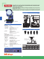
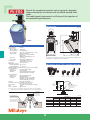
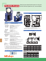
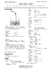
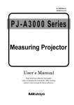
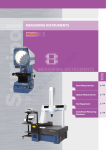
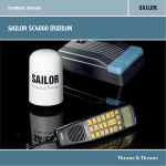
1
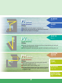
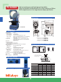
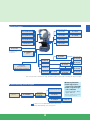
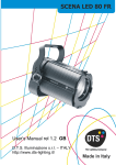
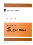
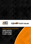
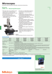
Optical Measuring
Profile Projector
PJ/PV/PH Series
Catalog No.E14005
PJ-H30 Series
Projector PJ-203
(Produced in 1958)
Each Mitutoyo profile projector is a measuring machine that performs measurement, inspection and observation efficiently by
projecting an image of a test workpiece on the stage onto a viewing screen under accurate magnification.
The inherently non-contact measurement method of profile projectors makes this type of instrument highly suitable for measuring
small parts that are unmeasurable with general-purpose contact instruments or easily deformed plastic parts, and can also be used
to observe the surface profiles of workpieces or inspect minute assemblies with surface illumination. Additionally, a wide selection of
accessories allows advanced measurement and inspection of various workpieces.
2
PJ Series
Screen diameter
300mm
● Applicable to a wide range of workpiece size
● Operations concentrated at the front of the instrument
● An extensive choice of workstages
PV
PJ-A3000
P4 - 5
PJ-H30
P6 - 7
PV-5110
Series
P8 - 9
Screen diameter
500mm
● Optimal for measurement compared with an enlarged drawing or tracing of
a projection image on the screen
● Clock components, electronic parts, precious metal parts, precision parts, etc.
PH Series
Screen diameter
350mm
● Observation/measurement of cutting tools (end mills,
lathe tools, tipped saws, etc.)
● Cylindrical form (screws, springs, etc.)
● Horizontal-beam design means easy workpiece loading/
unloading coupled with high weight-carrying capacity
of glassless stage.
PH-3515F,
PH-A14
P10 - 11
Stages
P12 - 13
Accessories
P14 - 18
Optical terms
basic knowledge
P19
3
PJ-A3000
High cost performance and high degree of operability
Stage-size selectable standard model with a screen diameter of 300mm
Built-in digital counter in the large character display specification
■ Dimensions
(Unit:mm)
742
374.9
400
1093
PJ-A3010F-200
854
Focal
point
焦点位置
■ Technical Data
Projected image:
Protractor screen
• Effective diameter:
• Screen material:
• Screen rotation:
• Angle reading:
• Cross hairs:
Projection lens:
Inverted
315mm (12.4 )
Fine-ground glass
±360°
, The counter displays up to ±370°
.
Digital counter (LED), Resolution: 1 or 0.01°(switchable)
Range: ±370°
, ABS/INC mode switching, Zero Set
90°Solid lines
10X (Standard accessory) Optional: 20X, 50X, 100X
External half-reflecting mirror for surface illumination
(only for 10x, 20x).
Bayonet mount
330
408
A
360
A: 95mm (3.74
67mm (2.64
86mm (3.39
233mm (9.17
Lens mount:
Magnification accuracy
• Contour illumination: ±0.1% or less
• Surface illumination: ±0.15% or less
Maximum workpiece height: Refer to the projection lenses (H) right.
Contour illumination
• Light source:
Halogen bulb (24V, 150W)
• Optical system:
Telecentric
• Functions:
2-step (High/Low) brightness switch,
Heat-absorbing filter, Cooling fan
Surface illumination
• Light source:
Halogen bulb (24V, 150W)
• Optical system:
Vertical illumination with adjustable condenser lens
• Functions:
Heat-absorbing filter, Cooling fan
Resolution for X/Y counter: 0.001mm or .0001 /0.001mm
(.00005 /0.001mm: digital head)
Power supply:
100 - 240V AC, 50/60Hz, power cord (2m)
Mass:
105kg - 140kg
Power consumption:
Approx. 400W
706
28
) ----------- PJ-A3005D-50
) ----------- PJ-A3010F-100
) ----------- PJ-A3005F-150
) ----------- PJ-A3010F-200
■ Projection lenses (10X is a standard accessory)
Halfreflecting
mirror F
for 10X
Halfreflecting
mirror F
for 20X
10X Lens
50X Lens
20X Lens
Set
D: Max. workpiece diameter
whose periphery can be focused
on the screen center
■ Main unit side panel
100X Lens
Set
D
Working
W distance
Max. workpiece
H height
Unit: mm
View field
W
H -50 models*
-100 models
-150 models
200 models
D -50 models*
-100 models
-150 models
200 models
■ Slide mechanism for replacing the tungsten-halogen lamp
10X
ø31.5
66 (20)
123.5
91
103.5
92.5
224 (198)
182
207 (198)
185
( ): When using surface illumination
4
Magnification
20X
50X
ø15.7
ø6.3
32.5 (2)
12.6
123.5
123.5
91
91
103.5
103.5
92.5
92.5
87 (61)
27
87 (61)
27
87 (61)
27
87 (61)
27
100X
ø3.1
5
123.5
91
103.5
92.5
10
10
10
10
■ System Diagram
Standard scale 50mm / 2
No.172-116 / No.172-117
Projection lens 10x Set
(Standard accessory)
No.172-202
Oblique reflection mirror
No.172-229
Reading scale 200mm / 8
No.172-118 / No.172-119
Projection lens 20x Set
No.172-203
Oblique reflection mirror
No.172-230
Reading scale 300mm / 12
No.172-161 / No.172-162
Projection lens 50x
No.172-204
Green filter
No.172-160-2
Projection lens 100x
No.172-207
※For PJ-A3005D-50
Green filter
No.172-160-3
※For PJ-A3010F-100,
PJ-A3005F-150, and
PJ-A3010F-200
Overlay chart set
No.12AAM027
(12 pcs.)
Rotary table
No.176-106
Swivel center support
No.176-105
PJ-A3005D-50
Rotary table with
fine feed wheel
No.172-198
PJ-A3005F-150
Machine stand
No.172-269
External dimensions:
500(W)×830(D)×650(H)mm
V-block with clamp
No.172-378
PJ-A3010F-100
PJ-A3010F-200
Holder with clamp
No.176-107
Stage adapter C
No.176-317
Rotary table with
fine feed wheel(A)
No.176-305
Swivel center support
No.172-197
Note: If an optional unit is installed on the stage, the H (Max. workpiece height) length is reduced by the optional unit height.
◆Lamp replacement
■ Data Processing System Diagram
Thermal printer with cable*
PJ-A3000 Series
main unit
RS-232C cable(2m, cross)
No.12AAA807
QM-Data200
Adjustable stand
No.172-270
(Arm type)
No.264-156*
Detector attachment(A)
No.12AAE671
For details, refer to the QM-Data200 and Vision Unit brochure.
*Order numbers differ depending on the connector form.
5
515530: High-luminance
halogen bulb of 24V/150W
512305 *: Long-life halogen
bulb of 24V/150W
(Long-life specification, Rating
approx. 500 hours)
* This lamp is a standard accessory. Illuminance
for Long life specification is rather low.
OPTOEYE 200
No.332-151
PJ-H30
•Design patent pending in Japan
Powerful PJ-series machine with the ultimate bright and crisp projection image.
Equipped with a high-rigidity main unit and linear scales, this series achieves
high-accuracy measurement.
A total of 8 models are available including one equipped with the long-stroke
stage of 300 x 179mm.
Provided with quick-release wheels for smooth and rapid operation of the stage.
Standard-equipped turret changes the projection lens smoothly and efficiently.
■ Dimensions
(Unit:mm)
382
155
PJ-H30A2017B
Projected image:
Protractor screen
• Effective diameter:
• Screen material:
• Screen rotation:
• Angle Reading:
• Cross hairs:
Projection lens:
Focal point
(焦点位置)
180∼230
50
127
■ Technical Data
Adjustment range
(上下動範囲)
0∼105
480∼585
985∼1090
796
Erect
306mm (12 )
Fine-ground glass
±360°
, The counter displays up to ±370°
.
Digital counter (LED)
Resolution: 1 or 0.01°(switchable)
Range: ±370°
ABS/INC mode switching, Zero Set
Solid lines
10X (Standard accessory)
Optional: 5X, 20X, 50X, 100X
Half-reflecting mirror for surface illumination
Parfocal lens
3-mount turret, Bayonet mount
50
243.5
374
404
285
270
86
50
16
365
745
816
■ Projection lenses (10X is a standard accessory)
Lens mount:
Magnification accuracy
• Contour illumination: ±0.1% or less
• Surface illumination: ±0.15% or less
Maximum workpiece height: 105mm (when rotary table is not equipped).
Contour illumination
• Light source:
Halogen bulb (24V, 150W)
• Optical system:
Zoom Telecentric
• Functions:
Non-stepped brightness adjustment,
Heat-absorbing filter, Cooling fan
Surface illumination
• Light source:
Halogen bulb (24V, 150W)
• Optical system:
Vertical / oblique illumination with an adjustable
condenser lens
• Functions:
Non-stepped brightness adjustment,
Heat-absorbing filter, Cooling fan
Focusing:
Projection screen head driving
PJ-H30A(manual), PJ-H30D(power drive)
Resolution for X/Y counter: 0.001mm or .0001 /0.001mm
Power supply:
ON/OFF switch, 100 - 240V AC, GND terminal, 50/60Hz,
power cord (2m)
Mass:
176kg - 212kg
Power consumption:
Approx. 420W
5X Lens
10X Lens
Max. workpiece
diameter whose peripheral
line can be focused on
the screen center
20X Lens
50X Lens
100X Lens
W Working distance
D
Max.
H workpiece
height
Unit: mm
View field
H
W
D
■ Main unit side panel
6
5X
ø61.2
105
66
148
10X
ø30.6
105
70.5
197
Magnification
20X
ø15.3
105
56.5
137
50X
ø6.12
105
50
114
100X
ø3.06
105
50
114
■ System Diagram
Standard scale 50mm / 2
No.172-116 / No.172-117
Projection lens 5X
No.172-271
Reading scale 200mm / 8
No.172-118 / No.172-119
Projection lens 10X
(Standard accessory)
No.172-472
Reading scale 300mm / 12
No.172-161 / No.172-162
Projection lens 20X
No.172-473
Overlay chart set
No.12AAM027 (12 pcs.)
Projection lens 50X
No.172-474
Green filter
No.12AAG981
Projection lens 100X
No.172-475
Adjustable stand
No.172-270
Lens cleaning set
No.12AAA165
Rotary table with
fine feed wheel
No.172-198
Size 1010
Size 2010
Rotary table with
fine feed wheel(A)
No.176-305
Stage adapter C
No.176-317
Stage adapter
No.176-304
Rotary table with
fine feed wheel(B)
No.176-306
Size 2017/3017
Swivel center support
No.176-105
Holder with clamp
No.176-107
V-block with clamp
No.172-378
Swivel center support
No.172-197
Note: If an optional unit is installed on the stage, the H (Max. workpiece height) length is reduced by the optional unit height.
■ Data Processing System Diagram
PJ-H30 Series
main unit
→Only for PJ-H30A
◆Lamp replacement
515530 *1: High-luminance
Detector mounting bracket
No.12AAG983
Detector attachment(A)
No.12AAE671
OPTOEYE 200
No.332-151
Thermal printer (with the connecting cable)*
Foot switch:No.937179T
QM-Data200 mounting stand QM-Data200 (Arm type)
No.12AAG982
No.264-156*
RS-232C cable(2m, cross)
No.12AAA807
Note) The connectors at
both ends are D-sub
9-pin female.
Foot switch
No.12AAA846
QM-Data200 (Stand type)
No.264-155*
RS-232C cable(cross)
No.12AAA807
Note) The connectors at
both ends are D-sub
9-pin female.
Adjustable stand
No.172-270
Thermal printer DPU414 for printing
counter and angle display values
(with connecting cable)*
halogen bulb of 24V/150W
512305 *2: Long-life halogen
bulb of 24V/150W
(Long-life specification, Rating
approx. 500 hours)
*1 This lamp is a standard accessory.
*2 Illuminance for Long life specification is rather low.
Real-time process control program MeasurLink
Inspection table generation program MeasureReport
Note: An appropriate PC is required.
For details, refer to the QM-Data200 and Vision Unit brochure.
*Order numbers differ depending on the connector form.
7
PV-5110
Optimal for comparative inspection such as tracing of a projected
image or observation of a contour with the 500mm forward-tilted
screen.
This model supports improvement in efficiency of the inspection of
mass-production precision parts.
■ Dimensions
(Unit:mm)
300
68
φ5
150
Projected image:
Protractor screen
• Effective diameter:
• Screen material:
• Screen rotation:
• Angle reading:
• Cross hairs:
• 0 Line (Index):
Projection lens:
960
■ Technical Data
1294
1627
PV-5110
Inverted
508mm (20 )
Fine-ground glass
±360°
, The counter displays up to ±370°
.
Digital counter (LED)
Resolution: 1 or 0.01°(switchable)
Range: ±370°
ABS/INC mode switching, Zero Set
90°Solid lines
Built-in, With a LED back light
10X (Standard accessory)
Optional: 5X, 20X, 50X, 100X
Insert type mount
470
1073
To mount the counter (KA-12) and counter stand, approximately 300mm space
is required on the right-hand side of the main unit.
Lens mount:
Magnification accuracy
• Contour illumination: ±0.1% or less
• Surface illumination: ±0.15% or less
Maximum workpiece height: Refer to the projection lenses (H) right.
Contour illumination
• Light source:
Halogen bulb (24V, 150W)
• Optical system:
Zoom Telecentric
• Functions:
2-step (High/Low) brightness switch,
Heat-absorbing filter, Cooling fan
Surface illumination
• Light source:
Halogen bulb (24V, 150W)
• Optical system:
Vertical illumination
• Functions:
Adjustable condenser lens, Oblique
illumination (for 5X, 10X and 20X),
Heat-absorbing filter, Cooling fan
Focusing:
Stage part drive, Manual
Resolution for X/Y counter: 0.001mm or .0001 /0.001mm
(using optional KA counter)
100 - 240V AC, 50/60Hz, power cord (2m)
Power supply:
Mass:
190kg
Power consumption:
Approx. 500W
Note) X and Y counters are not built into the PV-5110 main unit. If a counter display is
required, it is recommended that a QM-Data200 or KA-12 is purchased separately
● 5X, 10X, 20X Oblique surface illumination
535
620
■ Projection lenses (10X is a standard accessory)
PV-5110
5X
Lens set
10X
Lens set
Max.
workpiece H
height
20X
Lens set
50X
Lens set
100X
Lens set
Working
distance
W
D Max. workpiece
diameter whose periphery
can be focused on
the screen center
Stage glass
Projection lens
Unit: mm
Heat absorbing filter
Light source (reflector bulb)
View field
H
W
D
Surface illumination unit
5X
ø101.6
125
60 (27)
120
( ): When using surface illumination
8
10X
ø50.8
181
60
120
Magnification
20X
ø25.4
206
60
120
50X
ø10.16
87
32.4
64.8
100X
ø5.08
87
22.5
45
■ System Diagram
PV-5110 main unit
Standard scale 50mm / 2
No.172-116 / No.172-117
Projection lens 5X set
No.172-401
Projection lens 10X set
(Standard accessory)
No.172-402
Reading scale 200mm / 8
No.172-118 / No.172-119
Projection lens 20X set
No.172-403
Reading scale 300mm / 12
No.172-161 / No.172-162
Projection lens 50X set
No.172-404
Reading scale 600mm
No.172-329
Projection lens 100X set
No.172-405
Green filter
No.172-160-2
PV-5110
No.304-909
Canopy
No.172-319
External view:
1200(W)×1500(D)×2000(H)mm
KA-12 (Counter)
No.174-173*
Stage adapter C
No.176-317
Rotary table with
fine feed wheel
No.172-198
Swivel center support
No.176-105
Holder with clamp
No.176-107
V-block with clamp
No.172-378
Swivel center support
No.172-197
Note: If an optional unit is installed on the stage, the W (Working distance) length is reduced by the optional unit height.
*Order numbers differ depending on the connector form.
■ Data Processing System Diagram
PV-5110
QM-Data200*
Detector attachment(B)
No.12AAE672
Note: Arm type is
recommended for
PV-5110 (No.304-909)
OPTOEYE 200
No.332-151
Thermal printer
(with connecting cable)*
For details, refer to the QM-Data200 and Vision Unit brochure.
*Order numbers differ depending on the connector form.
9
◆Lamp replacement
512305 *: Long-life halogen
bulb of 24V/150W
*Illuminance for Long life specification is rather low.
PH-3515F, PH-A14
Optimal for contour observation/measurement of cutting tools
(end mills, lathe tools, tipped saws, etc.), screws and springs.
■ Dimensions
1138
PH-3515F
PH-A14
(Unit:mm)
1155
915
460
■ Technical Data
Projected image:
Protractor screen
• Effective diameter:
• Screen material:
• Screen rotation:
• Angle reading:
(for PH-3515F)
Erect*(PH-3515F), Inverted(PH-A14)
353(13.9 )mm (PH-3515F), 356(14 )mm (PH-A14)
Fine-ground glass
±360°
, The counter displays up to ±370°
.
Digital counter (LED)
Resolution: 1 or 0.01°(switchable)
Range: ±370°
ABS/INC mode switching, Zero Set
Vernier (graduation: 2 )
18
45
540
424
460
906
PH-3515F
*Refer to the page 13 for the dimensions of PH-A14.
To mount the optional counter (KA-12) and counter stand, approximately
300mm space is required on the right side of the main unit.
• Angle reading:
(for PH-A14)
• Cross hairs:
90°Solid lines
Projection lens:
10X (Standard accessory)
Optional:
5X (PH-3515 only), 20X, 50X, 100X
Lens mount:
Screw mount
Magnification accuracy
• Contour illumination: ±0.1% or less of nominal maginification
• Surface illumination: ±0.15% or less of nominal maginification
Maximum workpiece height: Refer to the projection lenses (L1) right.
Contour illumination
• Light source:
Halogen bulb (24V, 150W)
• Optical system:
Telecentric
• Functions:
2-step (High/Low) brightness switch: PH-3515F,
(Lit together with main power activation: PH-A14)
Heat-absorbing filter, Cooling fan
Surface illumination
• Light source:
Halogen bulb (24V 200W: PH-3515F),
(24V 150W, common to the contour illumination: PH-A14)
• Optical system:
Vertical illumination
• Functions:
Adjustable condenser lens,
Vertical/ Oblique surface illumination selectable: PH-3515F,
(Lit together with main power activation: PH-A14)
Heat-absorbing filter, Cooling fan
Focusing:
Stage part drive, Manual
Resolution for X/Y counter: 0.001mm or .0001 /0.001mm (using optional KA counter)
Power supply:
100 - 240V AC, 50/60Hz, power cord (2m)
Mass:
150kg (PH-3515F), 140kg (PH-14)
Power consumption:
Approx. 400W (PH-3515F), 200W (PH-A14)
Note1) X and Y counters are not built into the projector main unit. If a counter display is
required, it is recommended that a QM-Data200 or KA-12 is purchased separately.
Note2) The indicated value of a measurement may be slightly smaller than the actual value due
to optical distortion caused by the illumination conditions.
* The projected image of the workpiece is erect but inverted horizontally, which means that
the vertical orientation and displacement direction of the image is the same as on the
workpiece side, but the horizontal orientation and displacement direction are reversed.
■ Projection lenses (10X is a standard accessory)
Projection lens
L1
L2
D
H
Half-reflecting mirror F
Max. workpiece width
L
載物台
Working distance
W
Max.
workpiece H
height
D
Max. workpiece diameter whose periphery
can be focused on the screen center
PH-3515F
View field
L
W
D
H
■ Main unit side panel
Unit: mm
5X
70.6
175
160 (64)
152.4
152.4
10X
35.3
235
93 (35)
152.4
152.4
Magnification
20X
17.65
235
40
116
152.4
50X
7.06
80
14.6
30.4
152.4
( ): When using surface illumination
PH-A14
View field
L
W
D
H
10
Unit: mm
10X
35.6
235
93
130
102
Magnification
20X
50X
17.8
7.12
235
109
40
14.6
116
31.3
102
102
100X
3.56
109
9.5
19.2
102
100X
3.5
109
9.5
19
152.4
■ System Diagram
Projection lens 5X set
No.172-145 (PH-3515F)
For half-reflection mirror F
for 5X
No.172-294 (PH-3515F)
Reading scale 200mm / 8
No.172-118 / No.172-119
Reading scale 300mm / 12
No.172-161 / No.172-162
Projection lens 10X set
(Standard accessory)
No.172-184 (PH-3515F)/
No.172-011 (PH-A14)
For half-reflection mirror F
for 10X
No.172-295 (PH-3515F)
Surface illumination unit
No.172-133
Projection lens 20X set
No.172-173 (PH-3515F)/
No.172-012 (PH-A14)
Green filter
No.172-286
Projection lens 50X set
No.172-165 (PH-3515F)/
No.172-013 (PH-A14)
PH-3515F, PH-A14
main unit
Standard scale 50mm / 2
No.172-116 / No.172-117
(only for PH-3515F)
Projection lens 100X set
No.172-166 (PH-3515F)/
No.172-014 (PH-A14)
Overlay chart set
No.12AAM027
(12 pcs.)
Counter stand
No.12AAF182
Tipped-saw support stand*1
No.172-001
KA-12 (Counter)
No.174-173*2
1
No.172-001 No.172-002
Cutter support stand*
No.172-002
*2 Order numbers differ depending on the connector form.
*1 Mounting fixtures for tipped saws and cutters are
compatible with the center hole diameter of 25.4mm.
Vertical holder
No.172-132
Center support riser
No.172-143
Rotary vice
No.172-144
V-block with clamp
No.172-234
Center support
No.172-142
■ Data Processing System Diagram
PH-3515F
PH-A14
main unit
QM-Data200
(Arm type)
No.264-156
◆Lamp replacement
515530 *1: High-luminance
halogen bulb of 24V/150W
512305 *2: Long-life halogen
bulb of 24V/150W
(Long-life specification, Rating
approx. 500 hours)
Thermal printer
(with connecting cable)*
Adjustable stand
No.172-270
Detector attachment(A)
No.12AAE671
OPTOEYE 200
No.332-151
For details, refer to the QM-Data200 and Vision Unit brochure.
*Order numbers differ depending on the connector form.
11
12BAA637*1: Parabolic
halogen bulb 24V/200W
(for only PH-3515F)
*1 This lamp is a standard accessory.
*2 Illuminance for Long life specification is rather low.
Stage
PJ-A3000
XY range
PJ-A3000
main unit
Model
Order No.
Measuring unit
Quick-release mechanism
Top surface size
Effective size of stage glass
Stage glass thickness
Stage glass No.
Swivel adjustment range
Maximum loading
50×50mm
PJ-A3005D-50
302-704*
Digital micrometer head
̶
152×152mm
82×82mm
5mm
380405
100×100mm
PJ-A3010F-100
302-703*
Digital scale
X and Y axes
250×250mm
142×142mm
5mm
12BAE041
150×50mm
PJ-A3005F-150
302-702*
Digital scale
X and Y axes
280×152mm
185×84mm
6mm
381349
̶
̶
̶
10kg
10kg
8kg
200×100mm
PJ-A3010F-200
302-701*
Digital scale
X and Y axes
380×250mm
266×170mm
6mm
382762
±3˚
8kg
* To denote your AC power cable add the following suffixes to the order No.: A for UL/CSA, -1D for CEE, -1 DC for CCC, -1E for BS, -1K for KC, C and
No suffix are required for PSE.
PJ-H30
XY range
Model
Protractor screen
Order No.
Protractor screen/ Model
OPTOEYE built-in/
motor-driven focusing Order No.
Measuring unit
Quick-release mechanism
Top surface size
Effective size of stage glass
Stage glass thickness
Stage glass No.
Swivel adjustment range
Maximum loading
Measuring accuracy
100×100mm
PJ-H30A1010B
303-712*
PJ-H30D1010B
200×100mm
PJ-H30A2010B
303-713*
PJ-H30D2010B
303-732*
200×170mm
PJ-H30A2017B
303-714*
PJ-H30D2017B
303-733*
303-734*
High-accuracy digital scale
X and Y axes standard
350×280mm
410×342mm
250×150mm
270×240mm
6mm
8mm
382762
12BAD363
300×240mm
180×150mm
6mm
380412
300×170mm
PJ-H30A3017B
303-715*
PJ-H30D3017B
303-735*
510×342mm
370×240mm
8mm
12BAD330
±3˚ (right)
±5˚ (left)
10kg
20kg
(3+0.02L)μm L:Measured length(mm) The measurement method conforms to JIS B 7184.
* To denote your AC power cable add the following suffixes to the order No.: A for UL/CSA, D for CEE, DC for CCC, E for BS, K for KC, C and No suffix
are required for PSE.
12
PV-5110
XY range
PV-5110 main unit
Order No.
Measuring unit
Quick-release mechanism
Top surface size
Effective size of stage glass
Stage glass thickness
Stage glass No.
Swivel adjustment range
Maximum loading
200×100mm
304-919*
Digital scale
X and Y axes
380×250mm
266×170mm
6mm
382762
±3˚
5kg
* To denote your AC power cable add the following suffixes to the order No.: A for UL/
CSA, D for CEE, DC for CCC, E for BS, K for KC, C and No suffix are required for PSE.
PH-3515F
PH-A14
(Picture right is PH-3515F)
Dimensions of PH-A14
1158
Model No.
PH-3515F
PH-A14
XY range
254×152mm
200×100mm
PH main unit Order No.
172-868 *1
172-810*2
Measuring unit
Digital scale
−
Quick-release mechanism
Only X-axis
Top surface size
450×146mm
407×152.4mm
Dovetail groove
Two (Pitch = 43mm)
Minimum swivel angle
−
30
reading
Maximum measuring diameter
ø340mm
ø300mm
(horizontally fixed)*3
±10˚
−
Swivel adjustment range
Maximum loading
45kg
Photo: Cutter (Outside diameter of 175mm max.) is mounted on the tipped-saw
support fixture (No.172-001).
454
612
*1 To denote your AC power cable add the following suffixes to the order No.: A for UL/
CSA, D for CEE, DC for CCC, E for BS, K for KC, C and No suffix are required for PSE.
*2 To denote your AC power cable add the following suffixes to the order No.: -10A for
UL/CSA, -20D for CEE, -20DC for CCC, -20E for BS, -20K for KC.
*3 When using the projection lens 10X (Standard accessory) .
13
158
1240
Accessories (Optional)
■2-D Data Processing Unit QM-Data200 •Patented in Japan.
The QM-Data200 is a geometric readout/analysis unit for optical instruments such
as profile projectors. This unit features powerful 2-D coordinate measurement
capabilities with easy-to-use key operation. Measurement results can be visualized
on the LCD display and printed out if required.
■FEATURES
• High contrast color graphic displays on the large LCD screen with LCD back light.
• One-key operation for combined measurements that are often used (circle-circle distance, etc.)
• Equipped with the measurement procedure teaching function and measuring position navigation in Repeat mode.
• Easy measurement using combination of visual cross-hair alignment and automatic edge detection
(Optoeye positioning function).
• The AI measurement function (automatic identification of measuring item) eliminates switching between
the measurement command keys.
• The user menu function allows user to store measurement commands or part programs to create his/her own menu.
• Tolerance zone judgment of data processing result and statistical processing for each item are possible.
• Measurement result output to “MS-Excel®” in spreadsheet (CSV) format*
• The measurement procedure and measurement result can be saved, using USB memory.**
• Two models are available: a stand-alone type with tilt system and a flexible arm type that can be mounted on a
Profile Projector.
• Measurement possible even during printout
■Specifications
Code
* Ms-Excel® is a registered trademark of Microsoft Corporation.
** Operation is not assured for all commercial USB memories.
■Operation panel
QM-Data200
Stand-mount type
Arm-mount type
264-155 Note1
264-156 Note1
Japanese/English/German/French/Italian/Spanish/Portuguese/Czech/Chinese/
Display languages
Korean/Turkish/Swedish/Polish/Dutch/Hungarian
(selectable)
Measured value unit
Length: mm Angle: degree
Resolution
0.1μm / degree-minute-second (selectable)
Program functions
Part program creation, execution, editing
Number of data, maximum value, minimum value,
Statistical processing
mean value, standard deviation, range, histogram,
statistics on a measuring function basis (by command)
Display system
COLOR TFT LCD (with LED backlight)
Edge Sensor Position Compensation
Supported (Projector)
X,Y,Z: Maximum of three Linear Scales
FS: For connecting to optional foot switch
RS-232C 1: For connecting to external PC
PRINTER: For connecting to optional printer
RS-232C 2: For connecting to counter
Input/Output
USB-FD: For connecting to USB-FDD
of measuring instrument
USB-MEMORY: For connecting to
OPTOEYE: For inputting edge signal
USB memory
from OPTOEYE (OPTOEYE M2)
Measurement result
RS-232C output (CSV format, MUX-10 format)
file output
Power
AC100 - 240V
Maximum power
17W (does not include optional accessories)
consumption
External dimensions
Approximately 260×242×310
Approximately 318×153×275mm
(WxDxH)
(including the stand)
(when the arm is in the horizontal posture)
Mass
Approximately 2.9kg
Approximately 2.8kg
PJ-2500/PJ-3000 Series
PJ2500/PJ-3000 Series
PJ-A3000 Series, PJ-H30, PV-5110
Applicable models
PJ-H3000 Series, PV600A
PH-3515F (No.172-949), PH-A14
PH-3515F(No.172-847-5)
Standard accessories
AC adapter, power cable, Easy operation guide
Order No.
■Operation screen (tolerance zone measurement)
Tolerance zone measurement result can be checked
by color display at a glance.
Tolerance limit setting
Note1: To denote your AC power cable add the following suffixes to the order No.: A for UL/CSA, D for CEE, 00 for CCC
(power cord for CCC and User's Manual set of Simplified Chinese are provided for separately), E for BS, K for KC,
C and No suffix are required for PSE.
Note2: Refer to the QM-Data200 and Vision Unit leaflet (E14008) for more details.
Measurement result
14
■Rotary tables
120
84
172-198
172-198
176-106
176-306
176-305
Order No.
176-106
172-198
176-305
176-306
Product Name
Rotary table
Rotary table with fine feed wheel Rotary table with fine feed wheel A Rotary table with fine feed wheel B
Rotary stage size
ø112mm
ø146mm
ø240mm
ø270mm
̶
Fine adjustment
3
3
3
Effective glass diameter
ø60mm
ø96mm
ø182mm
ø238mm
̶
̶
Minimum angle reading
6
2
External dimensions
152x152x21.5
240x172x19.7
280x280x23.7
342x342x23.2
(WxDxH)mm
Mass
1.7kg
2.4kg
5.5kg
6.5kg
̶
̶
PJ-A3000
3
3
Applicable PJ-H30
̶
3
3
3
models
̶
̶
̶
PV-5110
3
Note: Rotary table with fine feed wheel (rotary stage size of ø315mm and effective glass diameter of ø280mm) is provided.
■Holder with clamp
■V-block with clamp
172-234
120
■Swivel center support
172-378
176-105
120
78
172-197
176-107
176-107
PJ-A3000 Series
Applicable models
PJ-H30 Series
PV-5110
Maximum width to be clamped
0 - 35mm
Mass
0.4kg
Order No.
Order No.
Applicable models
172-234
172-378
PJ-A3000
Series
PH-3515F
PJ-H30 Series
PH-A14 PV-5110
Maximum workpiece
diameter to be clamped ø50mm
Central height from a 38 - 48mm
mounting surface
Mass
1.24kg
■Adapter
Order No.
Product Name
External dimensions
(WxDxH)mm
Mass
PJ-A3000
Applicable PJ-H30
models
PV-5110
176-304
Stage adapter
176-317
Stage adapter (C)
50x340x15
73x278x17
1.5kg
1.8kg
3
3
3
̶
3
̶
ø25mm
38 - 48mm
0.8kg
220
Order No.
176-105
172-197
Maximum
ø70mm
ø80mm
workpiece size
to be clamped* (45x140mm) (65x140mm)
±10˚
±10˚
Inclination
Mass
2.4kg
2.5kg
*The maximum possible size to be measured differs
depending on the projection magnification selected.
The size enclosed in parentheses ( ) indicates that for an
inclination of 10°
15
15
Accessories (Optional)
■Center support
■Rotary vise
172-144
■Center support riser
172-143
172-142
172-144
PH-3515F
PH-A14
360˚
76mm
Order No.
Applicable models
Rotation range
Size between mounting
surface and top surface
Minimum angle reading
Mass
5˚
2.8kg
Order No.
Applicable models
Maximum
workpiece diameter
to be clamped
Mass
■Vertical holder
172-142
PH-3515F
PH-A14
120mm(240mm)
*
Order No.
Applicable models
Height
Mass
172-132
172-143
PH-3515F
PH-A14
60mm
2.2kg
Order No.
Applicable models
Glass size
Mass
172-132
PH-3515F
PH-A14
̶
1.3kg
3.3kg
* When center support riser (No.172-143)
is used.
■Standard scale
■Reading scale
Glass scale used for checking magnification accuracy
Glass scale specially designed for inspecting the magnified image of a standard
scale on the projection screen
172-116
Order No.
Range
Graduation
Accuracy
(20˚C)
172-116
50mm
172-330
80mm
0.1mm
(3+5L/1000)μm
L=Measured length(mm)
172-117
2
.01
(120+5L)
×10-6
L=Measured length (inch)
172-118
Order No.
Range
Graduation
Accuracy
(20˚C)
Order No.
Range
Graduation
Accuracy
(20˚C)
16
172-118
200mm
172-161
172-329
300mm
600mm
0.5mm
(15+15L/1000)
μm
L=Measured length(mm)
172-119
8
172-162
12
.02
×10-6
(600+15L)
L=Measured length(inch)
■オプトアイ200(投影像位置検出装置)
■オプトアイ内蔵(PJ-H30Dのみ)
■OPTOEYE (Projected image position detecting device)
■Built-in OPTOEYE (only PJ-H30D)
PJ-H30D
PJ-A3000 with OPTOEYE 200
Detecting sensor: Built in center of screen, non-directional
Illumination*, Minimum detectable circle: ø2mm (projected
image size), Minimum line width: 1mm (projected image size),
Repeatability: σ=1μm**
*Mitutoyo s condition
**Mitutoyo test condition
■Thermal printer DPU-414
OPTOEYE 200 and detector mounting plate A
• An edge detecting device for improving the measuring efficiency and reliability
of a profile projector by removing the need to position the cross hairs on an
edge manually. This has the effect of eliminating the operator variability factor
from data entry and shortening the measurement time.
• The detector uses an optical fiber that can be easily fixed on the screen with
chart clips.
• The device is provided with an error detection function that works if the screen
light intensity changes.
• This device can be retrofitted onto the QM-Data200 and does not need an AC
adapter since power is supplied from the QM-Data200 through the connecting
cable.
• The X and Y-axis linear scales on the projector main unit are directly
connected to the QM-Data200 during use of the Optoeye system.
• This system can be used in combination with the QM-Data200 but is only
available for the PJ-H30A. (PJ-H30D does not need this system because it has
a built-in Optoeye sensor.)
Order No.
Model
Illumination
Detecting directivity
Minimum detectable circle
Minimum detectable line width
Maximum response speed
Illumination range (Bright)
Bright-Dark field difference
Repeatability (contour illumination)
*Order numbers differ depending on the
connector form.
*Order numbers differ depending on the
Counter/angle display value printout*
connector form.
Print method
Dot-matrix thermosensitive method
Number of print digits
40 digits (normal character 9x7 dot-matrix)
Printing speed
Maximum 52.5 characters/sec (normal character)
(W)
(D)
x170
x65.5(H)
mm
160
External dimensions
(Printer main unit)
Printer cable, printer paper (1 roll),
Standard accessories
AC adapter (for 100VAC)
No.908353 (5 rolls)
Printer paper
* Counter/angle display value printout is for PJ-3000 series and PJ-H30 series.
Order No.
332-151
OPT-200
Contour/surface*
Non direction
ø2mm
1mm
1000mm/s
30 - 1500ℓX
20ℓX or higher
σ=1μm*
Connected to QM-Data200
■Adjustable stand
For QM-Data200 (stand-type
specification), thermal printer,
etc.
■Machine stand
* Mitutoyo s condition
Configuration of standard accessories
Electronic unit
Detector: Optical fiber
Connecting cable: For connecting electrical component main unit and QM-Data200
:For fixing the electrical component
Fixture for QM-Data200(No.12BAG139)
main unit to QM-Data200
Order No.
Platform
position
Platform size
Note) Detector mounting plate is an optional accessory.
17
172-270
Adjustable to a height of
720 to 1020mm
600x450mm
Order No. 172-269
External 500(W)x830(D)x650(H)mm
dimensions
*Recommended for PJ-A3000 series
Accessories (Optional)
■Overlay charts
To quickly check an image projected on the screen, an appropriate chart is used. 12 types of overlay charts are available according to the application.
Overlay chart No.11
Overlay chart No.12
Overlay chart No.13
Overlay chart No.14
Overlay chart No.15
Overlay chart No.16
Overlay chart No.17
Overlay chart No.18
Overlay chart No.19
Overlay chart No.20
Overlay chart No.21
Product name
Order No.
Overlay charts Set of 12 12AAM027
Overlay chart No.11
12AAM587
Overlay chart No.12
12AAM588
Overlay chart No.13
12AAM589
Overlay chart No.14
12AAM590
Overlay chart No.15
Overlay chart No.16
12AAM591
12AAM592
Specification
Set of 12 charts
(Overlay charts No.11 – No.22)
Upper side: radial lines (at intervals of 1°)
Lower side: concentric circles (at intervals
of 1mm in radius)
Concentric circles (at intervals of 5mm in
radius) with cross hairs (1mm graduation)
Concentric circles (at intervals of 1mm in
radius) with cross hairs
Horizontal: Parallel lines at intervals of
50mm (50-times enlargement of 1mm)
Vertical: Parallel lines at intervals of 20mm
(20-times enlargement of 1mm)
10mm-interval grids
Cross hairs (0.5mm graduation)
Overlay chart No.22
Product name
Overlay chart No.17
Overlay chart No.18
Overlay chart No.19
Overlay chart No.20
Overlay chart No.21
Overlay chart No.22
18
Order No.
12AAM593
12AAM594
12AAM595
Specification
1mm-interval grids
1°
-interval radial lines
Horizontal: 1mm-interval parallel lines
Concentric circles (at intervals of 1mm in radius)
12AAM596
and radial lines (at intervals of 1°
)
Metric screw for 20X lens: P = 0.2 to 2mm
12AAM597 Unified screw: 28 to 12 threads/inch
Whitworth screw: 20 to 10 threads/inch
Metric screw for 100X lens: P = 0.08 to 0.25mm
Involute tooth profile for 20X lens
12AAM598 (reference rack tooth profile)
20°
pressure angle: 0.2 to 1
14.5°
pressure angle: 0.2 to 1
Quick guide to Profile Projectors
■ Erect Image and Inverted Image
An image of an object projected onto a screen is erect if it is orientated
the same way as the object on the stage. If the image is reversed top to
bottom, left to right and by movement with respect to the object on the
stage (as shown in the figure below) it is referred to as an inverted image
(also known as a reversed image, which is probably more accurate).
Projection screen
F
F
An erect image
An inverted image
F
F
Top of the stage
■ Telecentric Optical System
An optical system based on the principle that the principal ray is aligned
parallel to the optical axis by placing a lens stop on the focal point on
the image side. Its functional feature is that the image will not vary in
size though the image blurs as the object is shifted along the optical axis.
For measuring projectors and measuring microscopes, an identical effect
is obtained by placing a lamp filament at the focal point of a condenser
lens instead of a lens stop so that the object is illuminated with parallel
beams. (See the figure below.)
Principal ray
Focal point on the image side
Optical axis
Light source
(lamp)
Object surface
Condenser lens
Workpiece
Projection lens
Telecentric contour illumination
Projection
screen surface
■ Working distance
Refers to the distance from the face of
the projection lens to the surface of a
workpiece in focus. It is represented by
L in the diagram below.
F Workpiece
X-axis movement
Y-axis movement
■ Magnification Accuracy
Projection lens
L
The magnification accuracy of a projector when using a certain lens is
established by projecting an image of a reference object and comparing
the size of the image of this object, as measured on the screen, with
the expected size (calculated from the lens magnification, as marked) to
produce a percentage magnification accuracy figure, as illustrated below.
Workpiece stage
Workpiece
The reference object is often in the form of a small, graduated glass scale
called a `stage micrometer’ or `standard scale’, and the projected image ■ Parallax error
of this is measured with a larger glass scale known as a `reading scale’. When a reading scale is used to measure the size of a workpiece
feature there is always a certain distance between the reading scale,
(Note that magnification accuracy is not the same as measuring accuracy.)
which is laid on the top of the stage glass, and the projected image
L− M
of the feature which is on the underneath surface. Unless the reading
=
̶
̶
̶
ΔM(%)
X 100
M
scale is always viewed from the same direction, ideally from directly
above, the image will appear to shift against the reading scale
ΔM(%): Magnification accuracy expressed as a percentage
graduations and thus cause a measurement error.
of the nominal lens magnification
L : Length of the projected image of the reference object
measured on the screen
: Length of the reference object
M : Magnification of the projection lens
■ Type of Illumination
Reading scale graduations
on this surface
PARALLAX ERROR
●Contour illumination: An illumination method to observe a
workpiece by transmitted light and is used mainly for measuring the
magnified contour image of a workpiece.
●Coaxial surface illumination: An illumination method whereby a
workpiece is illuminated by light transmitted coaxially to the lens
for the observation/measurement of the surface. (A half-mirror or a
projection lens with a built-in half-mirror is needed.)
●Oblique surface illumination: A method of illumination by obliquely
illuminating the workpiece surface. This method provides an
image of enhanced contrast, allowing it to be observed threedimensionally and clearly. However, note that an error is apt to occur
in dimensional measurement with this method of illumination.
(An oblique mirror is needed. Models in the PJ-H30 series are
supplied with an oblique mirror.)
19
CORRECT viewing diraection
INCORRECT viewing direction
Workpiece image projected
onto this surface
■ Field of view diameter
The maximum diameter of workpiece that can be projected using a
particular lens.
Screen diameter of profile projector
Field of view diameter (mm) =
Magnification of projection lens used
Example: If a 5X magnification lens is used for a projector with a
screen of ø500mm:
Field of view diameter is given by 500mm = 100mm
5
Mitutoyo Corporation
Specifications are subject to change without notice.
(Specifications in this catalog: As of June 2013)
Note: All information regarding our products, and in particular the illustrations, drawings, dimensional and performance data contained in this pamphlet, as well as other
technical data are to be regarded as approximate average values. We therefore reserve the right to make changes to the corresponding designs, dimensions and weights.
The stated standards, similar technical regulations, descriptions and illustrations of the products were valid at the time of printing. Only quotations submitted by ourselves
may be regarded as definitive.
Our products are classified as regulated items under Japanese Foreign Exchange and Foreign Trade Law. Please consult us in advance if you wish to export our products to
any other country. If the purchased product is exported, even though it is not a regulated item (Catch-All controls item), the customer service available for that product
may be affected. If you have any questions, please consult your local Mitutoyo sales office.
20-1, Sakado 1-Chome,
Takatsu-ku, Kawasaki-shi,
Kanagawa 213-8533, Japan
T +81 (0) 44 813-8230
F +81 (0) 44 813-8231
http://www.mitutoyo.co.jp
050 1306(1)C-(CH) HS, Printed in Japan
Export permission by the Japanese government may
be required for exporting our products according to
the Foreign Exchange and Foreign Trade Law. Please
consult our sales office near you before you export
our products or you offer technical information to a
nonresident.