1
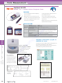
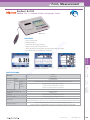
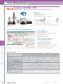
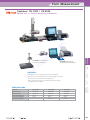
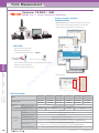
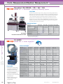
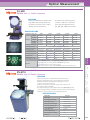
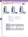
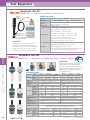
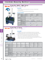
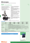
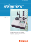
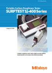
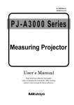
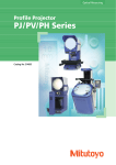
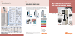
MEASURING INSTRUMENTS
i
m
u
w
w
s
.
w
Measuring
Instruments
o
p
m
o
.l c
p.162
p.170
p.174
p.179
Form Measurement
Surftest SJ-210
SERIES 178 — Portable Surface Roughness Tester
FEATURES
• 2.4" color LCD display includes backlighting
and over-size fonts
• Display direction can be changed to be read
vertically or horizontally right and left-handed
• Color tolerance judgments, evaluation curves
and all data can be displayed
SPECIFICATIONS
NEW!
SJ-210
178-561-01E
1000µin/.O8µin (25µm / 0.002 µm )
Detector
Primary profile (P), Roughness profile (R), DF profile, R-Motif
Ra, Rq, Rz, Ry, Rv, Rt, R3z, Rsk, Rku, Rc, RPc, RSm, Rmax*1 Rz1max,
Evaluation Parameters
S, HSC, RzJIS*2, Rppi, Rra, Rrq, Rlr, Rmr, Rmr(c ), Rc, Rk, Rpk,
Rvk, Mr 1, Mr2, A1, A2, Vo, Rpm, tp , Htp, R, Rx, AR
Display Unit Input / Output
USB, SPC, Printer output, RS-232C, Foot switch, MicroSD
Standards
JIS'82, JIS'94, JIS'01 , ISO, ANSI, VDA
Measurement Result Display Vertical, horizontal (invertible), curve, graph, value
Built-in Battery (Ni-MH)
4hrs. for full charge (approx. 1000 measurements)
Model No.
Order No. (inch / mm.)
Minimum Range/ Resolution
Measured Prof ile
Measuring
Form
Optical
Test
Instruments Measurement Measurement Equipment
o
p
i
m
u
s
.
w
Printer : 178-421 MAP
Connecting Cable : 12AALO67
To denote your AC line voltage
add the following suf fi xes
(e.g.178421A).
A for 120V, D for 230V
Coordinate
Measuring
Machines
Unit configuration:
① Printer main unit
② Printer connecting cable
③ Printing paper 6-pack
④ Battery pack 1piece
⑤ Exclusive use AC adaptor
(with AC power cord) 1piece
• Security management supports password
protected function locks
• A micro-SD card supports high-volume
portable data storage-up to 10,000 results
can be stored
• Multiple output options include RS-232C and
USB for maximum versatility
m
o
.l c
Simplified communication program for
SURFTEST SJ series
The Surftest SJ-210 has a USB interface, enabling data to be
transferred to spreadsheet or other software.
We also provide a program that lets you create inspection
record tables using a Microsoft Excel* macro.
w
w
Example of the connection with SJ-210
Example of the
output by
the printer
162
Tel. 0-2762-3000
www.sumipol.com
Form Measurement
Surftest SJ-310
SERIES 178 — Portable Surface Roughness Tester
Surftest SJ-310
FEATURES
•
•
•
•
•
•
Large color graphic LCD
Multilingual support
Complies with many industry standards
Displays assessed profiles and graphical data
User friendly, high-functionality display unit with integrated high-speed printer
Measurement results can be displayed in several ways
1-parameter display: one parameter
measurement result
w
w
SPECIFICATIONS
Model No.
Order No. (inch/mm)
X axis
Measuring
range
Range
Detector Range/
resolution
Display languages
Profile display: one parameter measurement
result and the measured profile
4-parameter display: four parameter
measurement results
SJ-310
(0.75mN type)
178-571-01E
16.0 mm (.63inch)
360 μm (-200 μm ~ +160 μm) [14400 μinch (-7900 μinch to +6300 μinch)]
360 μm / 0.02 μm (14400 μinch / .8 μinch)
100 μm / 0.006 μm (4000 μinch / .2 μinch)
25 μm / 0.002 μm (1000 μinch / .08 μinch)
In the measurement: 0.25mm/s (.01inch/s), 0.5mm/s (.02inch/s), 0.75mm/s (.03inch/s), In the return: 1mm/s (.04inch/s)
0.75mN / 2μmR 60°
400mN or less
JIS’82 / JIS’94 / JIS’01 / ISO’97 / ANSI / VDA
Primary, Roughness, DF, R-Motif, W-Motif
Ra, Rc, Ry, Rz, Rq, Rt, Rmax*1, Rp, Rv, R3z, Rsk, Rku, Rc, RPc, Rsm, Rz1max*2, S, HSC, RzJIS*3, Rppi, RΔa, RΔq, Rlr, Rmr,
Rmr(c), Rδc, Rk, Rpk, Rvk, Mr1, Mr2, A1, A2, Vo, λa, λq, L0, Rpm, tp*4, Htp*4, R, Rx, AR, W, AW, Wx, Wte, Possible Customize
Japanese, English, German, French, Italian, Spanish, Portuguese, Korean,
Traditional Chinese, Simplified Chinese, Czech, Polish, Hungarian Turkish, Swedish, Dutch
Tel. 0-2762-3000
www.sumipol.com
Coordinate
Measuring
Machines
Measuring speed
Measuring force / Stylus tip
Skid force
Standard
Measured profiles
Parameters
s
.
w
i
m
u
Measuring
Form
Optical
Test
Instruments Measurement Measurement Equipment
o
p
m
o
.l c
163
Form Measurement
Surftest SJ-410
SERIES 178 — Portable Surface Roughness Tester
FEATURES
•
•
•
•
•
m
o
.l c
Measuring
Form
Optical
Test
Instruments Measurement Measurement Equipment
Color-graphic LCD
Touch screen for easier operations
The display interface supports 16 languages.
Complies with many industry standards
A wide range, high-resolution detector
Measuring range/ resolution
800μm/0.01μm
80μm/0.001μm
8μm/0.0001μm
• More measuring functions than expected from a compact tester
• Narrow space measuring function (Patent pending in Japan)
• Simple contour analysis function
SPECIFICATIONS
Model No.
i
m
u
Parameters
s
.
w
w
w
Order No. (inch/mm)
X axis
Measuring
Z1 axis (detector unit)
range
Standard
o
p
SJ-411
SJ-412
178-581-01
25 mm (1 inch)
178-583-01
50 mm (2 inch)
800μm, 80μm, 8μm
*Up to 2,400μm with an optional stylus
JIS1982 / JIS1994 / JIS2001 / ISO1997 / ANSI / VDA
Ra, Rq, Rz, Ry, Rp, Rv, Rt, R3z, Rsk, Rku, Rc, RPc, RSm, Rmax*1, Rz1max*2, S, HSC, RzJIS*3, Rppi, RΔa, RΔq, Rlr, Rmr, Rmr(c),
Rσc, Rk, Rpk, Rvk, Mr1, Mr2, A1, A2, Vo, λa, λq, Lo, Rpm, tp*4, Htp*4, R, Rx, AR, W, AW, Wx, Wte, Possible Customize
Coordinate
Measuring
Machines
164
Tel. 0-2762-3000
www.sumipol.com
Form Measurement
Surftest SJ-500, SV-2100
SERIES 178 — with Dedicated Control / Display Unit
FEATURES
• User-friendly display and simple operation Equipped with a highly visible color 7.5-inch TFT LCD,
employing a color icon display and a touch panel achieves user-friendly display and simple operation.
• Easy positioning. A joy stick built in the dedicated control unit allows easy and quick positioning.
Fine positioning of a small stylus, required for measuring the inner side of a small hole, can be easily
made using the manual knob.
• Easy setting of measuring conditions for surface roughness. Equipped with simple input function
allows inputs according to drawing instruction symbols of ISO/JIS roughness standards.
Troublesome measuring condition settings can be easily input by directly selecting a drawing
instruction symbol for surface roughness from the menu.
SPECIFICATIONS
SJ-500
178-532-01E
178-533-01E
0.75mN
Model No.
Order No. (mm)
Order No. (inch/mm)
Measuring force of detector
SJ-500
178-532-02E
178-533-02E
4mN
50mm
6.7kg
X-axis measuring range
Vertical travel
Granite base size (WxD)
Dimensions (main unit, WxDxH)
Mass
SJ-2100M4
SJ-2100M4
178-636-01E
178-636-02E
178-637-01E
178-637-02E
0.75mN
4mN
100mm
350mm manual column
600 x 450mm
716 x 450 x863mm
144kg
m
o
.l c
o
p
i
m
u
s
.
w
Surftest SV-3100
SERIES 178 — Surface Roughness Testers
w
w
FEATURES
SV-3100S4
178-471-1E
178-481-1E
0.75mN
100mm
300mm power column
600 x 450mm
756 x 782 x 966mm
140kg
SV-3100H4
178-472-1E
178-482-1E
0.75mN
100mm
500mm power column
600 x 450mm
756 x 482 x 1166mm
150kg
SV-3100W4
178-473-1E
178-483-1E
0.75mN
100mm
500mm manual column
1000 x 450mm
1156 x 482 x 1176mm
220kg
SV-3100S8
178-476-1E
178-486-1E
Measuring force of detector 0.75mN
X-axis measuring range 200mm
Vertical travel
300mm power column
Granite base size (WxD)
600 x 450mm
Dimensions (main unit, WxDxH) 766 x 482 x 966mm
Mass (main unit)
140kg
Models without X-axis inclination function
SV-3100H8
178-477-1E
178-487-1E
0.75mN
200mm
500mm power column
600 x 450mm
766 x 482 x 1166mm
150kg
SV-3100W8
178-478-1E
178-488-1E
0.75mN
200mm
500mm manual column
1000 x 450mm
1166 x 482 x 1176mm
220kg
Model No.
Order No. (mm)
Order No. (inch)
Measuring force of detector
X-axis measuring range
Vertical travel
Granite base size (WxD)
Dimensions (main unit, WxDxH)
Mass (main unit)
Model No.
Order No. (mm)
Order No. (inch)
Coordinate
Measuring
Machines
• Mitutoyo's Surftest SV-3100 Series provide high-accuracy,
high-level analysis, and multi-functionality in three dimensional
analysis and measurement of fine contour, as well as the
conventional type surface roughness measurement.
• SURFPAK-SV, a dedicated data-analyzing software is installed.
This software allows data management in a consistent format,
from the work site to the laboratory.
• Ceramic, which is known for its superb anti-abrasive property, is
used as the X-axis drive unit guide. No lubrication of the guide
is required.
• High-accuracy glass scales are built-in on X-axis (resolution:
0.05μm) and Z2-axis (column, resolution: 1μm) to insure highaccuracy positioning. The SV-3100 series manifest high-reliability
especially in the horizontal roughness parameters (S, Sm), that
require high-accuracy of the X-axis travel.
• Equipped with various functions such as: the “straightness
compensation” function, which improves the linear accuracy of
the X-axis; the “circular compensation” function for the vertical
movement of the stylus; and the “stylus-tip diameter
compensation” function.
• An easy-to-operate Control Box is provided. The Control Box
independent of the main unit allows positioning, measurement
start/stop, retracting, and other operations to be performed
remotely. The Drive Unit up/down position and the X-axis traverse
can be fine controlled manually.
SPECIFICATIONS
Measuring
Form
Optical
Test
Instruments Measurement Measurement Equipment
SV-2100S4 SV-2100S4 SV-2100H4 SV-2100H4 SV-2100W4 SV-2100W4
178-680-01E 178-680-02E 178-682-01E 178-682-02E 178-684-01E 178-684-02E
178-681-01E 178-681-02E 178-683-01E 178-683-02E 178-685-01E 178-385-02E
4mN
0.75mN
4mN
0.75mN
4mN
Measuring force of detector 0.75mN
100mm
100mm
100mm
X-axis measuring range
350mm power column
550mm power column
550mm power column
Vertical travel
600 x 450mm
600 x 450mm
1000 x 450mm
Granite base size (WxD)
766 x 482 x 966mm
766 x 482 x 1166mm
1166 x 482 x 1176mm
Dimensions (main unit, WxDxH)
144kg
154kg
224kg
Mass
Model No.
Order No. (mm)
Order No. (inch/mm)
165
Form Measurement
Formtracer SV-C3200 / 4500
SERIES 525 — Surface Roughness / Contour Measuring System
FEATURES
• Detector with new arm design
• One-touch arm attachment
• SV-C4100 (Conventional product)
• SV-C4500
Screw fixing
• Fast traverse improves measurement efficiency
• Auto stop feature assures safety even during high-speed movement
SV-C3200S4
Contour Analysis Software: FORMTRACEPAK
Measuring
Form
Optical
Test
Instruments Measurement Measurement Equipment
Coordinate
Measuring
Machines
166
Contour analysis function
Contour-tolerancing function as a standard feature
Design value generation function
Data combination function
Simple pitch calculation function
o
p
i
m
u
SPECIFICATIONS
s
.
w
m
o
.l c
Contour Measuring
•
•
•
•
•
Surface Roughness Measuring
•
•
•
•
•
•
•
•
Surface Roughness analysis function
Microscopic contour analysis function
Simple input using drawing symbols
Multiple-point measurement function
Analysis function using multiple-point measurement
Reference length dialog box
Analysis condition modification with a preview function
R-surface automatic measurement function
w
w
SV-C3200S4
SV-C3200W4
SV-C3200S8
SV-C3200H8
SV-C3200W8
SV-C4500S4
SV-C4500W4
SV-C4500S8
SV-C4500H8
SV-C4500W8
525-481E-1
525-483E-1
525-486E-1
525-487E-1
525-488E-1
Order No. (mm)
525-441E-1
525-443E-1
525-446E-1
525-447E-1
525-448E-1
Specifications for Surface Roughness Measurement
Measuring X axis (drive unit)
100mm
200mm
Z1 axis (detector unit)
range
800μm / 80μm / 8μm
Straightness
(0.05+0.001L)μm L = Drive length (mm)
0.5μm / 200mm
0.01μm(800μm),0.001μm(80μm),0.0001μm(8μm)
Resolution Z1 axis (detector unit)
0.75mN or 4mN
Measuring force
60°
, 2μmR (Measuring force: 0.75mN) or 90°
, 5μmR (Measuring force: 4mN)
Stylus tip
JIS1982/JIS1994/JIS2001/ISO1997/ANSI/VDA
Conformable standards
Pa, Pq, Psk, Pku, Pp, Pv, Pz, Pt, Pc, PSm, PΔq, Pm(rC),Pmr, Pδc, Ra, Rq, Rsk, Rku, Rp, Rv, Rz, Rt, Rc, RSm, RΔq, Rm(rC),Rmr,
Rδc, Wa, Wq, Wsk, Wku, Wp, Wv, Wz, Wt, Wc, WSm, WΔq, Wm(rC),Wmr, Wδc, Rk, Rpk, Rvk, Mr1, Mr2, A1, A2, Rx, AR, R,
Parameters
Wx, AW, W, Wte, Ry, RyDIN, RzDIN, R3y, R3z, S, HSC, Lo, Ir, Δa, λa, λq, Vo, Htp, NR, NCRX, CPM, SR, SAR, NW, SW, SAW
Model
Tel. 0-2762-3000
www.sumipol.com
Form Measurement
Contracer CV-1000 / CV-2000
SERIES 218 — Contour Measuring Instruments
i
m
u
CV-1000N2 can be attached to
the optional column stand.
s
.
w
CV-1000N2 with personal
computer system and software
w
w
FEATURES
• The digital arc scale is equipped in the Z-axis detecting unit.
This gives you a wider range of measurement with higher resolution.
No more reliance on measurement magnifications.
• A data analysis system (personal computer system and software
of Formpak-1000) is available.
Model No.
Order No. (mm)
Order No. (inch)
X1-axis measuring range
Z1-axis measuring range
Z2-axis vertical travel
CV-1000N2
218-611E
218-621E
50mm
25mm
-
CV-2000M4
218-631E
218-641E
100mm
40mm
320mm
CV-2000S4
218-632E
218-642E
100mm
40mm
250mm
Coordinate
Measuring
Machines
SPECIFICATIONS
Measuring
Form
Optical
Test
Instruments Measurement Measurement Equipment
o
p
m
o
.l c
167
Form Measurement
Contracer CV-3200 / 4500
SERIES 218 — Contour Measuring Instruments
Contour Analysis Software:
FORMTRACEPAK
• FORMTRACEPAK functions offer total support for measurement
system control, surface roughness analysis, contour analysis,
contour tolerancing, and inspection report creation.
FEATURES
• Detector with new arm design
• One-touch arm attachment
CV-4100 (Conventional product)
CV-4500
Screw fixing
Measuring
Form
Optical
Test
Instruments Measurement Measurement Equipment
s
.
w
• Contour Analysis
w
w
SPECIFICATIONS
Coordinate
Measuring
Machines
Model
Order No. (mm)
X axis
Measuring
Z1 axis (detector unit)
range
Z2 axis (column) travel range
Scale unit
Resolution
Stylus up/down motion
Detector
Measuring direction
(Z1 axis (detector
Measuring face direction
unit))
Measuring force
Stylus traceable range
168
o
p
i
m
u
• Auto stop feature assures safety even during high-speed movement
• Hassle-free one-step calibration
• Best-in-class displacement accuracy
m
o
.l c
CV-3200H4
CV-3200W4
CV-3200S8
CV-3200H8
CV-3200W8
CV-4500H4
CV-4500W4
CV-4500S8
CV-4500H8
CV-4500W8
218-482E
218-483E
218-486E
218-487E
218-488E
218-442E
218-443E
218-446E
218-447E
218-448E
200mm
100mm
60mm (±30mm in horizontal situation)
300mm
500mm
300mm
500mm
Arc scale
CV-3200series: 0.04µm, CV-4500series: 0.02µm
Arc movement
Both pulling and pushing directions
CV-3200 series: Downward or upward
CV-4500 series: Both upward and downward (direction switch from FORMTRACEPAK)
CV-3200 series: 30mN (by adjusting weight)
CV-4500 series: 10, 20, 30, 40, 50mN (Setting measuring force FORMTRACEPAK)
Ascent 77°, Descent 83° (with one-sided cut stylus: standard accessory)
CV-3200S4
CV-4500S4
218-481E
218-441E
Tel. 0-2762-3000
www.sumipol.com
Form Measurement
Roundtest RA-120 / 120P / 10
SERIES 211 — Roundness Measuring Instruments
i
m
u
FEATURES
s
.
w
The Roundtest RA-120 / 120P are a compact, affordable, and simple-to-use device for measuring part geometry on the shop floor. It also provides
such superb data analysis capabilities as required with laboratory roundness measuring instruments and has a ±1000μm wide range detector and
precision turn table with excellent rotation accuracy. The RA-120 is a dedicated processor based model which controls all operations via the
control panel incorporated in the main unit.
SPECIFICATIONS
Model No.
Order No. (mm) (with DAT function)
w
w
Rotational
Radial
accuracy
Axial
Coordinate
Measuring
Machines
Rotation speed
Effective table diameter
Centering range adjustment
Turntable
Leveling range adjustment
Maximum probing diameter
Maximum workpiece diameter
Maximum turntable loading
Vertical travel
Vertical column
Maximum probing height
(Z-axis)
Maximum probing depth
Horizontal arm (X-axis) Horizontal travel
Measuring range
Measuring force
Detector
Standard stylus (12AAAB681)
RA-120
RA-120P
RA-10
211-622E
211-626E
211-601E
(0.04 + 6H / 10000)µm H : Probing height(mm) JISB7451-1997
(0.04 + 6X / 10000)µm X : Probing radius(mm)
6rpm
ø150mm
±3mm
±1°
ø100mm
ø280mm
ø320mm
ø440mm
10kg
25kg
117mm
280mm
152mm
280mm
100mm
165mm
±1000µm
70 ~ 100mN
Carbide ball, ø1.6mm (.06”)
Measuring
Form
Optical
Test
Instruments Measurement Measurement Equipment
o
p
m
o
.l c
169
Form Measurement/Optical Measurement
Roundtest RA-2200AS / DS / AH / DH
SERIES 211 — Roundness / Cylindricity Measuring System
FEATURES
The RA-2200 provides high accuracy, high speed and high performance
roundness measurement. The fully-automatic or DAT (Digital Adjustment
Table) function aids manual workpiece centering and leveling, turning
a once challenging task into something simple enough for even the
untrained user and substantially reducing overall measurement time.
The RA-2200 system comes with the ROUNDPAK, powerful data analysis
software, with enhanced functionality and easy operation thought the
use of the mouse and icon selection.
SPECIFICATIONS
RA-2200AS RA-2200DS RA-2200AH RA-2200DH
211-511E(mm) 211-513E(mm) 211-512E(mm) 211-515E(mm)
Order No.*
211-514E(inch)
211-516E(inch)
Effective table diameter
235mm
200mm
235mm
200mm
Centering/leveling adjustment** A.A.T.
D.A.T.
A.A.T.
D.A.T.
Centering range
±3mm
±5mm
±3mm
±5mm
Column travel
300mm (standard column)
500mm (high column)
Basic unit mass
180kg
200kg
Model No.
mm
inch
RA-2200AS
+ vibration isolator with side table.
* ATT: Automatic Adjustment Table
DAT: Digital Adjustment Table
i
m
u
PJ-A3000
Measuring
Form
Optical
Test
Instruments Measurement Measurement Equipment
SERIES 302 — Profile Projectors
s
.
w
SPECIFICATIONS
Model No.
Order No. (metric)
w
w
Order No. (inch/metric)
XY stage travel range
Measurement method
Floating function
XY stage table top size
XY stage effective area
Stage glass No.
Swiveling function
Max workpiece loading
Coordinate
Measuring
Machines
Remarks
Model No.
Order No. (metric)
FEATURES
• The PJ-A3000 Series profile
projectors are medium-size
models that feature high
versatility and easy operation.
• Easy-to-read digital XY
counter is located near the
projection screen to minimize
eye movement.
• Digital readout protractor
screen facilitates angle
measurement.
170
o
p
m
o
.l c
Order No. (inch/metric)
XY stage travel range
Measurement method
Floating function
XY stage table top size
XY stage effective area
Stage glass No.
Swiveling function
Max workpiece loading
Remarks
PJ-A3005R-50
302-709E
302-719E
50 x 50mm
Analog head
152 x 152mm
82 x 82mm
380405
8kg
PJ-A3005D-50
302-704E
302-714E
50 x 50mm
Rotary encoder
152 x 152mm
82 x 82mm
380405
8kg
w/o digital counter
PJ-A3005R-50E
302-708E
302-718E
50 x 50mm
Rotary encoder
152 x 152mm
82 x 82mm
380405
8kg
w/o angle counter
PJ-A3010F-100
302-703E
302-713E
100 x 100mm
Linear encoder
X and Y axes
250 x 250mm
142 x 142mm
12BAE041
10kg
-
PJ-A3010F-100E
302-707E
100 x 100mm
Linear encoder
X and Y axes
250 x 250mm
142 x 142mm
12BAE041
10kg
w/o angle counter
PJ-A3005F-150
302-702E
302-712E
150 x 50mm
Linear encoder
X and Y axes
280 x 152mm
185 x 84mm
381349
10kg
PJ-A3010F-200
302-701E
302-711E
200 x 100mm
Linear encoder
X and Y axes
380 x 250mm
266 x 170mm
382762
±3°
15kg
-
PJ-A3010F-200E
302-705E
200 x 100mm
Linear encoder
X and Y axes
380 x 250mm
266 x 170mm
382762
±3°
15kg
w/o angle counter
PJ-A3000
302-700E
Fixed
160 x 145mm
ø70mm
200673
8kg
w/o angle counter
-
PJ-A3005F-150E
302-706E
150 x 50mm
Linear encoder
X and Y axes
280 x 152mm
185 x 84mm
381349
10kg
w/o angle counter
Tel. 0-2762-3000
www.sumipol.com
Optical Measurement
PJ-H30
SERIES 303 — Profile Projectors
FEATURES
• Newly designed optical system with
high NA lenses provide drastically
brighter and clearer screen images
during surface illumination.
• The three-lens mounting turret
includes a 10X lens as standard.
Four types of projection lenses
(5X, 20X, 50X, 100X) are available.
SPECIFICATIONS
505B
Model No. (XY stage size)
PJ-H30E 303-701E
Vertical illumination
o
p
i
m
u
PV-5110
m
o
.l c
w
w
s
.
w
SERIES 304 — Profile Projectors
FEATURES
SPECIFICATIONS
Model No.
Order No.
XY stage travel range
Floating function
Measurement method
XY stage table top size
XY stage effective area
Stage glass No.
Swiveling function
Max workpiece loading
Remarks
Coordinate
Measuring
Machines
• Floor model that uses a downward illumination system.
• Digital readout protractor screen (including zero-setting,
ABS/INC coordinate switching functions) for easy and
error-free angle measurement.
• Angled screen allows projected images to be easily traced
or compared with a template.
• The optional oblique surface illumination unit (172-418) provides
clear and bright images, allowing easy inspection of non-reflection
workpieces such as plastic parts or printed materials.
Measuring
Form
Optical
Test
Instruments Measurement Measurement Equipment
Oblique illumination
1010B
2010B
2017B
3017B
303-705E
303-704E
303-703E
303-702E
PJ-H30A 303-711E
303-715E
303-714E
303-713E
303-712E
Order No. PJ-H30B 303-721E
303-725E
303-724E
303-723E
303-722E
PJ-H30C 303-741E
303-745E
303-744E
303-743E
303-742E
PJ-H30D 303-731E
303-735E
303-734E
303-733E
303-732E
300 x 170mm
200 x 170mm
200 x 100mm
100 x 100mm
XY stage travel range 50 x 50mm
(3+0.02L)µm, L = Measured length (mm)
Accuracy (at 20°C)
Measurement method Linear encoder Linear encoder Linear encoder Linear encoder Linear encoder
X and Y axes
X and Y axes
X and Y axes
X and Y axes
X and Y axes
Floating function
510 x 342mm
410 x 342mm
350 x 280mm
300 x 240mm
XY stage table top size 300 x 240mm
370 x 240mm
270 x 240mm
250 x 150mm
180 x 150mm
XY stage effective area 180 x 150mm
380412
12BAD330
12BAD363
382762
380412
Stage glass No.
±3°
±5°
±5°
±3°
±3°
Swiveling function
15kg
15kg
10kg
10kg
Max workpiece loading 10kg
E type: with fixed screen
A type: with protractor screen
B type: with protractor screen and built-in OPTOEYE edge sensor
Remarks
C type: with protractor screen and power focus
D type: with protractor screen, built-in OPTOEYE edge sensor and Power focus
PV-5110
304-909E
200 x 100mm
X and Y axes
Linear encoder
380 x 250mm
266 x 170mm
382762
±3°
5kg
-
171
Optical Measurement
PH-3515F
SERIES 172 — Profile Projectors
FEATURES
• Bench-top model that uses horizontal optical system.
• Suitable for thread pitch measurements—blurred
or distorted images will not be produced when
workpiece is angled.
• Digital angle measurement to 1' or 0.01º (PH-3515F).
• Heavy-duty workpiece table incorporates linear scales
for fast, accurate measurement.
SPECIFICATIONS
Model No.
Order No.
XY stage travel range
Measurement method
Quick-release mechanism
XY stage table top size
Swiveling function
Max stage loading
Remarks
o
p
m
o
.l c
PH-3515F
172-858E*
254 x 152mm
Linear encoder
X axis
450 x 146mm
±10°
45kg
-
* To denote your AC power cable add the following suffixes to the order No.: A for UL/CSA, CED for CEE,
i
m
u
CEE for BS, D for CEE, DC for CCC, E for BS, K for EK, No suffix is required for JIS/100V
Note) D and E are not compatible with CE
Measuring
Form
Optical
Test
Instruments Measurement Measurement Equipment
Coordinate
Measuring
Machines
172
** To denote your AC power cable add the following suffixes to the order No.: A for UL/CSA, D for CEE,
DC for CCC, E for BS, K for EK, No suffix is required for JIS/100V
s
.
w
TM-500
SERIES 176 — Toolmaker's Microscopes
w
w
FEATURES
• Angle measurement is performed easily
by turning the angle scale disc to align the
cross-hair reticle with the workpiece image.
• Illumination intensity can be adjusted.
SPECIFICATIONS
Model No.
Order No.
XY stage travel range
Measurement method
Floating function
XY stage table top size
Effective area of table
Max. workpiece height
Max. workpiece weight
Remarks
TM-505
176-811E
50 x 50mm
Micrometer head (optional)
152 x 152mm
96 x 96mm
115mm
5kg
-
TM-510
176-812E
100 x 50mm
Micrometer head (optional)
240 x 152mm
154 x 96mm
107mm
5kg
-
Tel. 0-2762-3000
www.sumipol.com
Optical Measurement
MF
SERIES 176 — Measuring Microscopes
FEATURES
• Observation with a clear and flare-less erect image and a wide field of view
• Measuring accuracy that is the highest in its class (and conforms to JIS B 7153)
• ML series, high-NA objectives that are specially designed for the MF series (long
working distance type)
• Illumination unit (reflected/transmitted) selectable from a high-intensity LED or
halogen bulb (required)
• Variable aperture diaphragm (reflected/transmitted) allows observation
measurement while suppressing light diffraction
• Variety of standardized stages in sizes up to 400×200mm
• Quick-release mechanism useful for moving the stage quickly when measuring
workpieces that are large in size or quantity
• Coarse/fine feed handles equipped as standard on both sides allow precise focus
and observation measurement regardless of handedness
• High-magnification eyepiece observation up to 2000×
• Standard measuring microscope that has a wide variety of optional accessories
including a Vision Unit and various digital CCD cameras
i
m
u
MF-B2017C
XY stage travel range: 200 x 170mm
(with optional binocular tube)
s
.
w
SPECIFICATIONS
Model No. (XY stage size)
Order No.*
MF-A
MF-B
1010C
2010C
2017C
3017C
4020C
176-666E*
176-665E*
176-664E*
176-663E*
176-662E*
176-686E*
176-685E*
176-684E*
176-683E*
176-682E*
400 x 200mm
300 x 170mm
200 x 170mm
200 x 100mm
100 x 100mm
220mm
220mm
220mm
150mm
150mm
Manual focusing (coarse focusing: 30mm/rev., fine focusing: 0.2mm/rev.)
Linear encoder (2-axis model: X / Y-axis, 3-axis model: X / Y / Z-axis)
0.001mm / 0.0005mm / 0.0001mm / .0001" / .00005" / .00001"
XY-aixs: (2.2+0.02L)µm, L = Measuring length (mm) when not loaded, JIS B 7153
Z-axis: (5+0.04L)µm, L = Measuring length (mm)
X and Y axes with Quick-release mechanism
610 x 342mm
510 x 342mm
410 x 342mm
350 x 280mm
280 x 280mm
280 x 280mm
440 x 240mm
370 x 240mm
270 x 240mm
250 x 150mm
180 x 180mm
180 x 180mm
±3° (left)
±5° (left)
±5° (left)
15kg
20kg
20kg
10kg
10kg
10kg
220mm
220mm
220mm
150mm
150mm
150mm
w
w
Coordinate
Measuring
Machines
XY stage travel range
Z-axis travel range
Focusing method
Measurement method
Resolution (switchable)
Measuring accuracy (at 20°C)
Indication accuracy (at 20°C)
Floating function
XY stage top size
Effective glass size
Swiveling function
Max. stage loading
Max. workpiece height
505C
176-661E*
176-681E*
50 x 50mm
150mm
Measuring
Form
Optical
Test
Instruments Measurement Measurement Equipment
o
p
m
o
.l c
* The following suffixes to the order No. (e.g. : 176-661-10) : -10 for English user’s manual, 11 for Chinese user’s manual, No suffix is Japanese user’s manual
Selection of machine type
Machine type
Measurement system
MF-A
X and Y-axis (2-aixs type)
MF-B
X, Y and Z-axis (3-axis type)
Illumination Unit
Applicable Illumination Unit
Order No.
LED
176-345*
Halogen
176-347*
* To denote your AC power cable add the following suffixes to the order No.: A for UL/CSA, C for Taiwan, D for CEE,
DC for CCC, E for BS, K for EK, No suffix is required for JIS/100V
173
Test Equipment
HM-211 / 221
SERIES 810 — Micro Hardness Testing Machines
Measuring
Form
Optical
Test
Instruments Measurement Measurement Equipment
i
m
u
FEATURES
Coordinate
Measuring
Machines
• The latest electromagnetic force motor
used in the loading mechanism has
enabled the test force to be freely selected
(see test force specifications over the wide
range of 0.4903mN (0.05gf ) to 19810mN
(2kgf ). It is also possible to freely set the
time for loading and load dwell time. Now
your desire for absolute control over the
indentation size in Vickers hardness testing
can be satisfied. The HM-200 series always
offers the test force most appropriate for
the specimen material and shape.
• It is possible to perform not only the
Vickers hardness test but also a fracture
toughness test (IF test: JIS R 1607-1995)
on ceramics.
s
.
w
w
w
SPECIFICATIONS
Model No.
Order No.
Test force range
Test force control
Control unit
Video monitor
Indenter/objective turret
No. of indenter mount
No. of objective mount
174
o
p
m
o
.l c
• The objectives used enable a very
comfortable working distance between
the objective and the specimen surface.
This greatly reduces the possibility of
collision between the specimen and the
objective during focusing operations.
(e.g. 1.1mm for 50X objective)
• The contrast that is most appropriate
for the magnification of the objective
can be obtained by manipulating the
variable aperture stop in the illumination
unit. This makes the indentations clearly
visible, leading less variation and reducing
the chance of error when measuring the
diagonal lengths.
HM-211
810-400E, 810-403E
98.07mN to 980.7mN (9.807mN increments),
980.7mN to 9807mN (98.07mN increments)
HM-221
810-405E, 810-408E
0.4903mN,
0.9807mN to 9.807mN (0.9807mN increments),
9.807mN to 980.7mN (9.807mN increments),
980.7mN to 19610mN (98.07mN increments)
Force generation by electromagnetic and automatic control (load, dwell, unload)
Touch screen type (expect for 810-403, 810-408)
Motor driven and manual operation
Motor driven and manual operation
2
2
4 (10X, 50X and 100X are standard accessory)
4 (10X and 50X are standard accessory)
Tel. 0-2762-3000
www.sumipol.com
Test Equipment
HM-101 / 102 / 103 / 112 / 113
SERIES 810 — Micro Hardness Testing Machines
HM-101
Economical manual type
FEATURES
HM-103
The TV monitor removes fatigue
in visual measurement, reducing
detecting errors.
HM-102
Economical digital type
SPECIFICATIONS
HM-101
Model No.
810-124E
Order No.
Test force range
By dial
Test force setting
Control unit
Video monitor
Indenter/objective turret Manual type
1
No. of indenter mount
1 (observation),
No. of objective mount
1 (measurement)
HM-112
Digital display of
measurement results and a
statistical calculation function.
o
p
i
m
u
s
.
w
m
o
.l c
HM-102
HM-103
HM-112
HM-113
810-125E
810-959E
810-126E
810-969E
98.07, 245.2, 490.3, 980.7, 1961, 2942, 4903, 9807mN
By dial
By dial
By dial
By dial
Durable sheet switch type
Touch screen type
9" B/W
9" B/W
Manual type
Manual type
Manual type
Manual type
1
1
1
1
2 (measurement) 2 (measurement) 2 (measurement) 2 (measurement)
AVK-CO, HV-112 / 113 / 114 / 115
SERIES 810 — Vickers Hardness Testing Machines FEATURES
w
w
Test force range
Test force setting
Control unit
Video monitor
Indenter/objective turret
No. of indenter mount
No. of objective mount
AVK-C0
810-160E
9.807, 49.03, 98.07,
196.1, 294.2, 490.3N
By dial
Manual operation
1
1 (measurement)
Coordinate
Measuring
Machines
• Back-lit LCD graphic display for Indentation
size (D1 and D2), Hardness value and scale,
Number of measurement point Test conditions
(HV / HK indenter type, test force, load duration),
GO / ±NG tolerance judgment, Cylindrical and
spherical surface compensation and offset
• Remote control of power turret
• Conversion to other hardness scales
• Statistical processing
SPECIFICATIONS
Model No.
Order No.
• A wide range of test force from 1.961N
to 490.3N* is available for measuring a
various type of specimens.
The load duration can be set in 1sec
increments between 5 and 99sec.
The minimum reading of indentation is
0.1μm. It allows small indentations to be
measured with high precision.
Function: Control unit
Measuring
Form
Optical
Test
Instruments Measurement Measurement Equipment
• A wide range of test force from
4.903x10⁻³N to 19.61N is available
for measuring a various type of
specimens. The load duration can
be set in 1sec increments between
5 and 99sec*. The minimum reading
of indentation is 0.01μm*. It allows
small indentations to be measured
with high precision.
*HM-112, HM-113
HM-113
Reduce individual differences in
visual measurement with the TV
monitor. The statistical calculation
function reduces operation time.
HV-115
HV-114
810-165E
810-985E
9.807, 19.61, 29.42, 49.03, 98.07,
1.961, 2.942, 4.903, 9.807, 24.51,
196.1, 294.2, 490.3N
49.03, 98.07, 196.1N
By dial
By dial
By dial
By dial
Touch screen type
9" B/W
9" B/W
Motor driven
Motor driven
Motor driven
Motor driven
1
1
1
1
2 (measurement) 2 (measurement) 2 (measurement) 2 (measurement)
HV-112
810-163E
HV-113
810-981E
175
Test Equipment
HR-521 / 522 / 523
SERIES 810 — Rockwell Type Hardness Testing Machines
o
p
FEATURES
Measuring
Form
Optical
Test
Instruments Measurement Measurement Equipment
Coordinate
Measuring
Machines
176
m
o
.l c
• Indenter escape function for continuous
• Multiple test force generation for
testing at fixed table position.
Rockwell, Rockwell Superficial
This eliminates instability caused by
and Brinell hardness.
the table retraction.
• Dolphin-nose indenter arm for easy
reach of interior (min. ø40mm/ø22mm*) • Auto-stop elevation table and automatic
preliminary test force loading to provide
and exterior surfaces.
stable test force generation.
*When using an optional diamond
indenter (19BAA292).
• Real time electronic test force control
for accurate loading. This perfectly
eliminates load force overshooting.
i
m
u
s
.
w
w
w
SPECIFICATIONS
Model No.
Order No.
Preliminary test force
Test force
Test force setting
Stage elevation
Control unit
HR-521
810-202E
29.42N, 98.07N
HR-522
HR-523
810-203E
810-204E
29.42N, 98.07N
29.42N, 98.07N
Rockwell superficial: 147.1, 294.2, 441.3N
Rockwell superficial: 147.1, 294.2, 441.3N
Rockwell: 588.4, 980.7, 1471N
Rockwell: 588.4, 980.7, 1471N
Brinell: 61.29, 98.07, 153.2, 245.2, 294.2,
Brinell: 1839N
306.4, 612.9, 980.7, 1226, 1839N
By control unit
By control unit
By control unit
Manual
Manual
Power drive
Touch screen type
Touch screen type Touch screen type
Tel. 0-2762-3000
www.sumipol.com
Test Equipment
HR-200 / 300 / 400
SERIES 963 — Rockwell Hardness Testing Machines
m
o
.l c
HR-210MR
HR-320MS
HR-430MS
Rockwell hardness testing machine
Dual type (Rockwell/Rockwell
superficial) hardness testing machine
Twin type (Rockwell/Rockwell superficial
combined use) hardness test equipment
FEATURES
SPECIFICATIONS
Model No.
Code No.
Type of hardness test
Total test force control
Test force duration
Maximum specimen height
Maximum specimen depth
Fanction
Data output
Power supply
Dimensions
Mass
s
.
w
w
w
HR-210MR
963-220
-
Analog
0.5HR graduation
Automatic pre-setting dial gauge
-
HR-320MS
963-231
Rockwell
HR-430MS
963-241
Rockwell superficial
JIS B 7726 ISO6508-2 (ASTM E18)
Digital
0.1HR graduation
Loading navigator indication
Automatic steering wheel brake
Dial switching
Dial switching
Weight change
Motor drive
Motor drive
Button start
Automatic start
3-60s setting or manual operation
Fixed 3-5.5s or manual
180mm (100mm if cover is attached)
165mm (from indenter axis to the frame)
Success or failure decision function
Offset revision function
Hardness conversion function
Digimatric (SPC), RS-232C
AC100-240V, 1.2A
Approximately 235(W) x
Approximately 235(W) x 516(D) x 780(H) mm
512(D) x 780(H)mm
Approximately 47 kg
Approximately 50 kg
Coordinate
Measuring
Machines
Standard
Display
Minimum reading
Preliminary test force
(handling support)
Preliminary test force setting
Total test force setting
i
m
u
• The digital type (HR-320MS, HR-430MR and HR-430MS)
has digimatic output and our Digimatic Mini-Processor
(DP-1VR) to print and input tools (USB-ITN-E) to connect
to a PC and use for data transfer.
• Brinell hardness tests can be performed by using the
following optional accessories: a Brinell indenter,
a weight set and a measurement microscope.
Measuring
Form
Optical
Test
Instruments Measurement Measurement Equipment
o
p
• The newly designed frame provides maximum clearance for positioning the workpiece.
A flat table is all that is needed for mounting these testing machines.
• Simple to operate
With analogue type (HR-110MR, HR-210MR), the gauge presetting operation
is unnecessary by the adoption of an automatic presetting dial gauge.
• HR-110MR does not require a power source, and is considered to be environmental
friendly.
• The digital type (HR-430MR and HR-430MS), with the adoption of the automatic
steering wheel brake & the automatic load sequence, with only simple handling test
possibility.
177
Test Equipment
Hardmatic HH-411
SERIES 810 — Impact Type Hardness Testing Unit
SPECIFICATIONS
Impactor
built-in
carbide ball
Model
Order No.
Display unit
Impactor
Display unit
810-298: ASTM standard
810-299: JIS standard
Including the display unit,
D type impactor (810-287)
and carbide ball (19BAA457).
Display range
FEATURES
HH-411 is a rebound type portable hardness
tester for metal with a compact body and high
operability. It allows anyone to perform hardness
testing easily at the touch of a key, so it can be
used widely on various components in the field.
Functions
o
p
i
m
u
Hardmatic HH-300
m
o
.l c
Measuring
Form
Optical
Test
Instruments Measurement Measurement Equipment
SERIES 811 — Durometers for Rubber and Plastics Hardness Testing
s
.
w
w
w
SPECIFICATIONS
Model No.
Order No.
Digital
Dial
Digital
Dial
Scale
Applications
Resolution
Range
Coordinate
Measuring
Machines
Standards
-
JIS K 6253
4
4
44 x 18mm
ø18mm
ISO 7619
JIS K 7215
Pressure foot
Spring force (mN)
Indenter
Tip angle
Indenter diameter
Indenter protrusion
Functions
Type
Dimensions
(WxDxH)
Mass
HH-336-01
HH-336
HH-332
HH-335-01
HH-335
HH-331
811-336-01
811-336
811-332
811-335-01
811-335
811-331
Shore A
Natural rubber, soft elastomers, etc.
0.5 (digital) or 1 (dial)
HA: 10 - 90
DIN 53 505
ISO 868
Digital
Dial
Digital
Dial
4
4
4
FEATURES
Digital / Dial Durometers are suitable
for testing the nature of the following
materials — natural rubber, neoprene,
polyesters, P.V.C., leather, Thiokol, nitrite
rubber, wax, vinyl, cellulose acetates,
glass polystyrene, etc.
4
4
4
4
4
4
ASTM D 2240
178
HH-411
810-299-02 (JIS)
810-298 (ASTM)
Impact hammer with integrated detector and carbide-ball tip
(D type: conforming to ASTM A 956)
7-segment LCD
Leeb: 1-999HL
Resolution 1 HL
Vickers: 43-950HV Resolution 1 HV
Brinell: 20-894HB
Resolution 1 HB
Rockwell C: 19.3-68.2HRC
Resolution 0.1 HRC
Rockwell B: 13.5-101.7HRB
Resolution 0.1 HRB
Shore: 13.2-99.3HS Resolution 0.1 HS
Tensile strength: 499-1996MPa Resolution 1 MPa
(Display range depends on conversion table.)
Auto Angle Compensation Function, Offset function
OK/NG judgment function, Conversion function
Data storage function: 1800 data entries
Statistical analysis (Average, Maximum, Minimum, Dispersion)
Auto sleep function, Impact counter display function
HH-334
HH-338-01
HH-338
HH-333
HH-337-01
HH-337
811-334
811-338-01
881-338
811-333
811-337-01
881-337
Shore D
Hard elastomers, plastics, hard rubber, ebonite, etc.
0.5 (digital) or 1 (dial)
HD: 20 - 90
4
4
4
-
4
4
4
4
4
4
4
4
44 x 18mm
ø18mm
444.5H (Hardness reading: 20-90)
Blunt taper (Tip diameter: 0.79mm)
Sharp point (Tip curvature: 0.1±0.01mm)
35°±0.25°
30°±0.5°
1.25mm
2.5mm
Digital: Data hold, Zero -setting, SPC output, Power ON/OFF
(Power supply: SR44 x 1pc.) Analog Durometer: Peak retaining hand
Long-leg
Compact
Compact
Long-leg
60 x 28.5 x 151mm
60 x 28.5 x 151mm
60 x 28.5 x 193mm
60 x 28.5 x 193mm
56 x 33.5 x 144mm
56 x 33.5 x 144mm
56 x 33.5 x 186mm
56 x 33.5 x 186mm
290g
290g
310g
310g
300g
300g
320g
320g
550+75H (Hardness reading: 10-90)
Tel. 0-2762-3000
www.sumipol.com
Coordinate Measuring Machines
Quick Scope
SERIES 359 — CNC / Manual Vision Measuring System
SPECIFICATIONS
QS250Z
QS200Z
200mm
200mm
250mm
200mm
Range
100mm
100mm
0.5µm
Resolution
Reflective linear encoder
Length standard
XY: (2.5+6L/1000)µm, Z: (5+6L/1000)µm
Measuring accuracy (at 20°C)*
2.5X, 1X, 5X 2.5X, 1X, 5X 0.5X - 3.5X zoom 0.5X - 3.5X zoom
Objective
Magnification
21X - 147X
On monitor 105X (at 2.5X) 105X (at 2.5X) 21X - 147X
High-resolution 1/3" color CCD camera
Image detecting unit
Surface: co-axial light, fiber-optic ring light Contour: stage light
Illuminations
269 x 311mm
269 x 261mm 269 x 311mm 269 x 261mm
Table glass size
110mm
110mm
110mm
110mm
Max. workpiece height
10kg
10kg
10kg
10kg
Max. workpiece weight
465 x 815 x 663mm, 76kg
Dimensions (W x D x H), Mass
Model No.
X-axis
Y-axis
Z-axis
FEATURES
• Surface, contour and fiber-optic ring light illumination
options allow users to configure the QS lighting to
meet a variety of measurement needs.
• Powerful, Windows® based QSPAK software is easy to
use and offers a wide spectrum of measuring and
analysis capabilities.
• Functions include zoom, auto-focus, measurement
playback, one-click edge detection, graphic display, 48
different macros, and a pattern matching function for
several common part features.
• X,Y stage can be controlled by mouse or through the
optional multi-function control box.
QS200
200mm
200mm
100mm
FEATURES
Model No.
Range
• QV series standard model ranging in size from compact to large.
• The PRO machine is equipped with RGB color LED illumination, a programmable power
turret (PPT) and a programmable ring light (PRL) as standard. The laser auto focus (LAF)
option is also available.
• The lineup, including the PRO2 zooming machine and PRO3 with a color CCD, can
satisfy a wide range of needs.
• The traverse speed in the X and Y axes reaches 400 mm/second in the QV-APEX404/606.
This greatly contributes to throughput improvement, particularly for workpieces that
involve a large range of travel.
s
.
w
w
w
X-axis
Y-axis
Z-axis
Accuracy*
Illumination
(PRL: Programmable Ring Light)
E1XY
E1Z
E2XY
Surface
Contour
PRL
Magnification change system
Max. drive speed
Stage glass size
Max workpiece height
Max. stage loading
Dimensions(W x D x H)**
Mass**
X/Y-axis
Z-axis
Coordinate
Measuring
Machines
Resolution
High-sensitivity CCD camera
QV Apex606PRO
QV Apex404PRO
QV Apex606PRO2
QV Apex404PRO2
QV Apex606PRO3
QV Apex404PRO3
Hyper QV606PRO
Hyper QV404PRO
600mm
400mm
650mm
400mm
250mm
250mm
0.1μm [0.02μm]
B&W (PRO3 model: color)
(1.5+3L/1000)μm [(0.8+2L/1000)μm]
(1.5+4L/1000)μm [(1.5+2L/1000)μm] [PRO2 model: (4.0+5L/1000)μm]
(2+4L/1000)μm [(1.4+3L/1000)μm] [PRO2 model: (2.5+4L/1000)μm]
LED, RGB (PRO2 and PRO3 models: Halogen)
LED, white (PRO2 and PRO3 models: Halogen)
LED, RGB (PRO2 and PRO3 models: Halogen)
Programmable power turret (PRO2 model: Programmable power zoom lens)
400mm/s [200mm/s]
400mm/s [200mm/s]
300mm/s [200mm/s]
300mm/s [200mm/s]
300mm/s [200mm/s]
300mm/s [200mm/s]
493 x 551mm
697 x 758mm
399 x 271mm
250mm
250mm
200mm
40kg [30kg]
50kg [40kg]
20kg [15kg]
1027 x 1407 x 1778mm
1309 x 1985 x 1794mm
859 x 951 x 1609mm
579kg
1450kg
360kg
QV Apex302PRO
QV Apex302PRO2
QV Apex302PRO3
Hyper QV302PRO
300mm
200mm
200mm
Measuring
Form
Optical
Test
Instruments Measurement Measurement Equipment
i
m
u
o
p
SERIES 363 — CNC Vision Measuring System
SPECIFICATIONS
m
o
.l c
*When using 2.5X objective or the zoom lens in 2.5X magnification
(Magnification on monitor: 105X), L = Measuring length (mm)
QV Apex / Hyper QV
QV Apex302PRO
QS250
200mm
250mm
100mm
* The measuring accuracy is defined at the following conditions, Programmable power turret: 1X, Objective set: 2.5X, L = Dimension between two arbitrary points (mm)
In PRO2, the zoom magnification is 3X.
** Including machine stand
179
Coordinate Measuring Machines
Crysta-Plus M433 / M500 Series
SERIES 196 - Manual - Floating Type CMM
FEATURES
• Smooth operation due to high-precision air bearings and lightweight
moving members.
• Continuous fine feed over the entire measuring range.
SPECIFICATIONS
Model No.
Crysta-Plus M443
400mm
400mm
300mm
X-axis
Y-axis
Z-axis
Range
Resolution
E
R
Material
Work table Size
Tapped insert
Max. height
Workpiece
Max. loading
Mass (main unit)
Accuracy*
Crysta-Apex S Series
m
o
.l c
624 x 805mm
480mm
360kg
Measuring
Form
Optical
Test
Instruments Measurement Measurement Equipment
o
p
i
m
u
SERIES 191 - Standard CNC CMM
(3.0+4.0L/1000)μm
Crysta-Plus M544 Crysta-Plus M574
500mm
500mm
700mm
400mm
400mm
0.5μm
(3.5+4.0L/1000)μm
4.0μm
Granite
764 x 1175mm
764 x 875mm
M8 x 1.25mm
595mm
180kg
450kg
575kg
FEATURES
s
.
w
w
w
• Designed and constructed using all Mitutoyo’s experience in CNC CMM
technology, CRYSTA-Apex S and Crysta-Apex C feature lightweight materials
and an innovative machine structure, providing high motion stability,
high accuracy, and affordability. The temperature correction function
(16°C to 26°C) can yield accurate measurements even on the shop floor. In
addition to point-to-point measurement, the MPP-310Q and Metris Laser probes
provide a contact/non-contact scanning function.
SPECIFICATIONS
Model No.
Coordinate
Measuring
Machines
Crysta-Apex S544 Crysta-Apex S574 Crysta-Apex S776 Crysta-Apex S7106 Crysta-Apex S9106 Crysta-Apex S9166 Crysta-Apex S9206
(Crysta-Apex S9108) (Crysta-Apex S9168) (Crysta-Apex S9208)
X-axis
505mm
505mm
705mm
705mm
905mm
905mm
905mm
405mm
705mm
705mm
1005mm
1005mm
2005mm
1605mm
Range
Y-axis
405mm
405mm
605mm
605mm
605mm(805mm) 605mm(805mm) 605mm(805mm)
Z-axis
Resolution
0.1μm
(1.7+3L/1000)μm, (1.7+4L/1000)μm**
MPEE
1.7μm
Accuracy* MPEP
2.3μm
MPETHP
Material
Granite
638 x 860mm 638 x 1160mm 880 x 1420mm 880 x 1720mm 1080 x 1720mm 1080 x 2320mm 1080 x 2720mm
Work table Size
Tapped insert
M8 x 1.25mm
545mm
545mm
800mm
800mm
800mm(1000mm)
Max. height
Workpiece
180kg
800kg
1000kg
1200kg
1500kg
1800kg
Max. loading 180kg
625kg
1675kg
1951kg
515kg
2231kg(2261kg) 2868kg(2898kg) 3912kg(3942kg)
Mass (main unit)
* The machine is equipped with the temperature compensation system.
According to ISO 10360-2 methods when using the SP25M probe system with a ø4 x 50mm stylus. L: Measuring length (mm)
** Guaranteed accuracy temperature range: 16°C - 26°C.
180
Tel. 0-2762-3000
www.sumipol.com