1
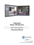
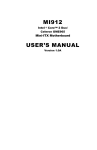
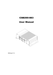
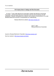
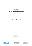
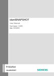
AMI400 Series User Manual 2009 April V2.0 Copyright © 2008 IBASE Technology INC. All Rights Reserved. No part of this manual, including the products and software described in it, may be reproduced, transmitted, transcribed, stored in a retrieval system, or translated into any language in any form or by any means, except documentation kept by the purchaser for backup purposes, without the express written permission of IBASE Technology INC. (“IBASE”). Products and corporate names mentioned in this manual may or may not be registered trademarks or copyrights of their respective companies, and are used for identification purposes only. All trademarks are the property of their respective owners. Every effort has been made to ensure that the contents of this manual are correct and up to date. However, the manufacturer makes no guarantee regarding the accuracy of its contents, and reserves the right to make changes without prior notice. 2 Table of Contents Accessories ........................................................................................................... 6 Components.......................................................................................................... 7 Front View ................................................................................................................... 7 Rear View (AMI400-9) .................................................................................................. 8 Rear View (AMI400-8) ................................................................................................ 10 Specification ........................................................................................................12 Mounting AMI400 to the Wall ..............................................................................14 Wall mounting requirements ...................................................................................... 15 Selecting the location ................................................................................................. 16 Exploded view of the AMI400 assembly – AMI400-9 .............................................17 Parts description ........................................................................................................ 18 Exploded view of the AMI400 assembly – AMI400-8 .............................................19 Parts Description ........................................................................................................ 20 Driver Installation ................................................................................................22 BIOS Setup ...........................................................................................................23 3 Safety Information Your AMI400/401 series is designed and tested to meet the latest standards of safety for information technology equipment. However, to ensure your safety, it is important that you read the following safety instructions. Setting up your system • Read and follow all instructions in the documentation before you operate your system. • Do not use this product near water. • Set up the system on a stable surface or secure on wall with the provided rail. Do not secure the system on any unstable plane or without the rail. • Do not place this product on an unstable cart, stand, or table. The product may fall, causing serious damage to the product. • Slots and openings on the chassis are for ventilation. Do not block or cover these openings. Make sure you leave plenty of space around the system for ventilation. Never insert objects of any kind into the ventilation openings. • This system should be operated from the type of power indicated on the marking label. If you are not sure of the type of power available, consult your dealer or local power company. • Use this product in environments with ambient temperatures between 0˚C and 45˚C. • If you use an extension cord, make sure that the total ampere rating of the devices plugged into the extension cord does not exceed its ampere rating. Care during use • Do not walk on the power cord or allow anything to rest on it. • Do not spill water or any other liquids on your system. • When the system is turned off, a small amount of electrical current still flows. Always unplug all power, and network cables from the power outlets before cleaning the system. • If you encounter the following technical problems with the product, unplug the power cord and contact a qualified service technician or your retailer. The power cord or plug is damaged. Liquid has been spilled into the system. The system does not function properly even if you follow the operating instructions. The system was dropped or the cabinet is damaged. 4 Lithium-Ion Battery Warning CAUTION: Danger of explosion if battery is incorrectly replaced. Replace only with the same or equivalent type recommended by the manufacturer. Dispose of used batteries according to the manufacturer’s instructions. NO DISASSEMBLY The warranty does not apply to the products that have been disassembled by users 5 Accessories a. Power Cord x 1 b. M/B Manual x 1 c. Driver CD x 1 d. Power Brick x 1 e. Mounting Rail Screw x 6 f. Mounting Rail x 2 6 Components Front View Refer to the diagram below to identify the components on this side of the system. PWR The power LED illuminated when system been power on. HDD The hard disk LED blinks when data is being written into or read from the hard disk drive. RES The reset switch allows reset the system. ON/OFF The power switch allows powering ON and OFF the system. USB The USB (Universal Serial Bus) port is compatible with USB devices such as keyboards, mouse devices, cameras, and hard disk drives. USB allows many devices to run simultaneously on a single computer, with some peripheral acting as additional plug-in sites or hubs. 7 Rear View (AMI400-9) Refer to the diagram below to identify the components on this side of the system. M/S The PS/2 mouse port is use to connect PS/2 mouse. K/B The PS/2 keyboard port is use to connect PS/2 compatible devices such as keyboard, MSR and scanner. COM1 Communication or serial port one is compatible with RS-232 interface. VGA Video Graphic Array (VGA) port supports a VGA-compatible device such as a monitor or projector. The system default display output port. LAN The eight-pin RJ-45 LAN port supports a standard Ethernet cable for connection to a local network. 8 USB The USB (Universal Serial Bus) port is compatible with USB devices such as keyboards, mouse devices, cameras, and hard disk drives. USB allows many devices to run simultaneously on a single computer, with some peripheral acting as additional plug-in sites or hubs. 1394 IEEE 1394 interface connector. DVI The Digital Visual Interface (DVI) port supports a high quality VGA-compatible device such as a monitor or projector to allow viewing on a larger external display. SPDIF Plug a standard SPDIF optical audio cable into this connector for digital audio transfer. BASS/REAR/SIDE/LINE IN/FRONT/MIC Analog audio output connector. Please refer M/B manual to connect analog audio signal out to get stereo or 5.1 channels signal. PCI SLOT There is one 33MHz/32bit standard PCI slot for half size PCI card expansion. DC IN The supplied power adapter converts AC power to DC power for use with this jack. Power supplied through this jack supplies power to the system. To prevent damage to the system, always use the supplied power adapter. 9 Rear View (AMI400-8) Refer to the diagram below to identify the components on this side of the system. M/S The PS/2 mouse port is use to connect PS/2 mouse. K/B The PS/2 keyboard port is use to connect PS/2 compatible devices such as keyboard, MSR and scanner. S-VIDEO Super Video is a Y/C analog video signal output port that carries luma and chroma signals to any display which support this interface such as projector, TV. TV-OUT Composite Video port (RCA connector) is format of an analog television (picture only) signal to any display which supports this interface such as projector, TV. COM1 Communication or serial port one is compatible with RS-232 interface. VGA Video Graphic Array (VGA) port supports a VGA-compatible device such as a monitor or projector. The system default display output port. 10 LAN The eight-pin RJ-45 LAN port supports a standard Ethernet cable for connection to a local network. USB The USB (Universal Serial Bus) port is compatible with USB devices such as keyboards, mouse devices, cameras, and hard disk drives. USB allows many devices to run simultaneously on a single computer, with some peripheral acting as additional plug-in sites or hubs. 1394 IEEE 1394 interface connector. SPDIF Plug a standard SPDIF optical audio cable into this connector for digital audio transfer. LINE IN The stereo headphone jack (3.5mm) is used to connect the audio signal into system to record or bypass it to storage or LINE OUT. LINE OUT The stereo audio jack (3.5mm) is used to connect the system’s audio out signal to amplified speakers or headphones. MIC The microphone jack is designed to connect the microphone used for video conferencing, voice narrations, or simple audio recordings. PCI SLOT There is one 33MHz/32bit standard PCI slot for half size PCI card expansion. DC IN The supplied power adapter converts AC power to DC power for use with this jack. Power supplied through this jack supplies power to the system. To prevent damage to the system, always use the supplied power adapter. 11 Rear View (AMI401-945F-D1) Refer to the diagram below to identify the components on this side of the system. M/S The PS/2 mouse port is use to connect PS/2 mouse. K/B The PS/2 keyboard port is use to connect PS/2 compatible devices such as keyboard, MSR and scanner. COM1 Communication or serial port one is compatible with RS-232 interface. VGA Video Graphic Array (VGA) port supports a VGA-compatible device such as a monitor or projector. The system default display output port. LAN The eight-pin RJ-45 LAN port supports a standard Ethernet cable for connection to a local network. 12 USB The USB (Universal Serial Bus) port is compatible with USB devices such as keyboards, mouse devices, cameras, and hard disk drives. USB allows many devices to run simultaneously on a single computer, with some peripheral acting as additional plug-in sites or hubs. 1394 IEEE 1394 interface connector. DVI The Digital Visual Interface (DVI) port supports a high quality VGA-compatible device such as a monitor or projector to allow viewing on a larger external display. SPDIF Plug a standard SPDIF optical audio cable into this connector for digital audio transfer. BASS/REAR/SIDE/LINE IN/FRONT/MIC Analog audio output connector. Please refer M/B manual to connect analog audio signal out to get stereo or 5.1 channels signal. PCI SLOT There is one 33MHz/32bit standard PCI slot for half size PCI card expansion. DC IN The supplied power adapter converts AC power to DC power for use with this jack. Power supplied through this jack supplies power to the system. To prevent damage to the system, always use the supplied power adapter. 13 Specification System Mainboard MI910E / MB899EF / MI945F Construction Aluminum Chassis Color Silver Storage 2.5” 80GB SATA HDD x 1 Mounting Desktop or wall mount Dimensions 226(W) x 109(H) x 263.5(D)mm (8.9” x 4.29” x 10.37”) Power Supply 150W DC adapter Operating 0°C ~ 45°C (32°F ~ 113°F) Temperature Storage -20°C ~ 80°C Temperature Relative Humidity 5~95% @45°C (non-condensing) Vibration HDD: 0.25g/5~500Hz random operation RoHS Available ‧This specification is subject to change without prior notice. Mounting AMI400 to the Wall 14 Using attached mounting rail, you can install AMI400 on wood, drywall surface over studs, or a solid concrete or metal plane. Ensure the installer uses at least four M4 length 8mm screws to secure the system on wall. Six M4 length 8mm screws are recommended to secure the system on wall. Fasteners are not included with the unit, and must be supplied by the installer. The types of fasteners required are dependent on the type of wall construction. Choose fasteners that are rated either ”Medium Duty“ or ”Heavy Duty.“ To assure proper fastener selection and installation, follow the fastener manufacturer’s recommendations. Wall mounting requirements Note: Before mounting the system on wall, ensure that you are following all applicable building and electric codes. When mounting, ensure that you have enough room for power and signal cable routing. And have good ventilation for power adapter. The method of mounting must be able to support weight of the AMI400 plus the suspend weight of all the cables to be attached to the system. Use the following methods for mounting your system: 15 Mounting to hollow walls Method 1: Wood surface – A minimum wood thickness – 38mm (1.5in.) by 25.4 cm (10in.) – of high, construction – grade wood is recommended. Note: This method provides the most reliable attachment of the unit with little risk that the unit will come loose or require ongoing maintenance. Method 2: Drywall walls - Drywall over wood studs is acceptable. Mounting to a solid concrete or brick wall - Mounts on a flat smooth surface. Selecting the location Plan the mounting location thoroughly. Locations such as walkway areas, hallways, and crowded areas are not recommended. Mount the unit to a flat, sturdy, structurally sound column or wall surface. The best mounting surface is a standard countertop, cabinet, table, or other structure that is minimally the width and length of the unit. This recommendation reduces the risk that someone may accidentally walk into and damage the device. Local laws governing the safety of individuals might require this type of consideration. 16 Exploded view of the AMI400 assembly – AMI400-9 12 13 1 14 15 2 16 17 3 18 19 20 21 4 22 23 5 24 6 25 7 26 8 9 10 11 17 Parts description Part NO. Description Part NO. Description 1 HDD 2 HDD Cover 3 Top chassis 4 Heat pipe 5 ID392 DVI board 6 MI910E 7 CPU FAN bracket 8 PCI Bracket 9 Rear panel 10 MI910E I/O Shield 11 DC extension cable 12 SATA signal cable 13 SATA power cable 14 Screws for SB heat sink 15 Screws for SB heat sink 16 Southbridge heat sink 17 ATX power extension cable 18 ID737 19 I D450 20 Control panel cable 21 USB extension cable 22 PCI Expansion Card Bracket 23 IP115 24 Front panel 25 Bottom chassis 26 Mounting rail 18 Exploded view of the AMI400 assembly – AMI400-8 11 12 1 13 2 14 15 3 16 17 18 4 19 5 20 6 21 7 22 8 9 10 19 Parts Description Part NO. Description Part NO. Description 1 HDD 2 HDD Cover 3 Top chassis 4 Heat pipe 5 MB899EF 6 CPU FAN bracket 7 PCI Bracket 8 Rear panel 9 MB899EF I/O Shield 10 DC extension cable 11 SATA signal cable 12 SATA power cable 13 ATX power extension cable 14 ID737 15 I D450 16 Control panel cable 17 USB extension cable 18 PCI Expansion Card Bracket 19 IP115 20 Front panel 21 Bottom chassis 22 Mounting rail 20 Exploded view of the AMI400 assembly – AMI400-945F-D1 14 15 1 2 3 4 5 16 6 17 7 18 19 8 9 20 10 21 11 12 13 21 Parts Description Part NO. Description Part NO. Description 1 HDD Cover 2 Top chassis 3 IP115 4 Screw for SB heat sink 5 Southbridge heat sink 6 Heat pipe 7 ID392 DVI board 8 MI945F 9 Control panel cable 10 PCI Expansion Card Bracket 11 Rear panel w/ I/O Shield 12 Bottom chassis 13 Mounting rail 14 HDD 15 SATA cable 16 USB extension cable 17 ID450 18 Front panel 19 ID737 20 DC extension cable 21 ATX power extension cable 22 Driver Installation Please refer correspond mainboard user manual to install the driver properly. BIOS Setup Please refer correspond mainboard user manual to configure BIOS setting. 23