1
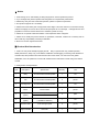
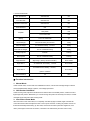
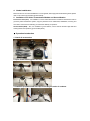
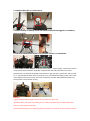
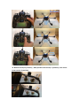
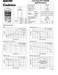
SkyhawkRC F700 user manual
V1.11
July.2.2014
Thanks for using SkyhawkRC F700 aircraft. Please read this manual carefully before
operation, it will help you understand this product deeply and make sure to operate it
safely and correctly(the aircraft has been tested well before delivery, parameters has
been set and matched properly, please do not adjust the trimming button if
unnecessary in order to avoid the aircraft appearing incapable of flight).
Ⅰ. Disclaimer
Ⅱ. Notice
Ⅲ. Product Brief Introduction
Ⅳ. Function Introduction
Ⅴ. Operation Introduction
Ⅶ. Other Attentions
Ⅰ. Disclaimer
This product is remote controlled aircraft, wrong and impertinent operation will cause unintended
consequences. We will not bear any legal responsibility in the process of use. If you use this product, it
indicates that you have accepted this clause.
Ⅱ. Notice
1. Under the age of 16, after drinking or taking drugs person cannot operate this product.
2. If you are beginners, please operate under the guidance of experienced professionals.
3. Please stay away from the crowd while operation, please to operate in special site.
4. This product supports 4S Li-Po battery.
5. Please ensure the battery has enough power before flight, ensure the receiver is connected correctly,
make sure all plugs no loose or fall off, ensure all spare parts are of no damage,
fuselage structure and
propellers no loose and screws without loss. Otherwise, please do not fly.
6. Please do not operate under bad weather or the temperature below 5 degrees.
7. Please do not modify this product without our permission, otherwise, it will be out of warranty and we
will not take any responsibility caused by modification.
8. Be sure to use the original accessories.
Ⅲ. Product Brief Introduction
1. F700 is an entry-level aerial photography aircraft.
Easy to operate and carry, flexible operation,
stable performance, ready to fly, avoid tedious installation and debugging. Its working mode divides into
manual mode, GPS position hold mode and auto return home mode, can control two axis gimbal
stabilization, also can update and connect with wireless video transmission module and ground station
module.
2. Configuration and Specification
Item
Description
Specification
Quantity
Unit
1
Body
3K carbon fiber+industrial plastic
1
set
2
Arm
3K carbon fiber+industrial plastic
6
pieces
3
Landing Gear
3K carbon fiber+industrial plastic
1
set
4
Motor
C3510 KV560
6
pieces
Propeller
1255 plastic
(option)
1355 carbon fiber
3
pairs
Gimbal
2 axis brushless
(option)
(available to GOPRO)
1
set
7
Brushless ESC
3-5S 20A high-speed
6
pieces
8
Flight Controller
GPS+INS
1
set
5
6
3. Technical Parameter
Max Spread Size
990x990x360
mm
Color Box Size
820x355x170
mm
Aluminum Case Size
800x335x270
mm
Motor Distance
690
mm
1255 plastic
inch
1355 carbon fiber
inch
Battery
1*LiPo 4S 10000mAh
pc
Aircraft Weight
Not include battery and receiver
1800g
Take Off Weight
4S 10000mAh battery + receiver
2500g
Max Take Off Weight
1PC 4S 10000mAh battery
3700g
Safety Payload
GOPRO
≤1000g
Max Payload
1PC 4S 10000mAh battery
≤1200g
Flight Distance
Sight range(limit by remote controller)
about 1000m
Flight Time 1
4S 10000mAh 1PC battery、receiver
about 25min
Propeller
4S 10000mAh 1PC battery、receiver、
Flight Time 2
about 20min
gimbal + GOPRO
Wind Resistance
≤5
class
Ⅳ. Function Introduction
1. Manual Mode
Under manual mode, it comes with auto stabilization function, manual control its flight height of aircraft
and forward/backward, left/right, up/down, turn left/right operations.
2. GPS Positon Hold Mode
Under hovering mode, adjust the throttle stick and rudder stick to the middle position, it will lock current
flight height and position. Meanwhile, you can also change the positon of aircraft by two sticks, it will lock
new flight height and positon after loosing sticks.
3. Auto Return Home Mode
After auto return home mode starts, it is completely controlled by flight controller, flight controller will
control the aircraft rotate and adjust the front to return point and return to taking off position and turn off
throttle automatically while landing. (In this mode, aircraft has 20 meters protection height limit, if the
return point height is lower than 20 meters, it will climb to 20 meters firstly and then return home).
4. Gimbal stabilization
M700 aircraft can control the stabilization of 2 axis gimbal, while equipped with brushless gimbal, please
refer to user manual of brushless gimbal carefully.
5. Available to FPV Video Transmission Module and Ground Station
First Person View (FPV)
It is available to connect video transmission module and transmit live video to
ground by video transmission system, enjoy the pleasure of FPV. Meanwhile, stabilization, hovering and
auto return home functions will help you relieve the difficulty of operation.
Ground Station(GCS)
Also, it is available to ground station, can live monitor aircraft’s flight data and
working states and operate by ground station(GCS).
Ⅴ. Operation Introduction
1. Check all accessories
2. Open folded landing gears and arms
3. Install the propellers and lock clips according the order of numbers.
4. Install the GPS bar on center board.
5. Fasten battery on battery board and insert battery alarm(suggest to set battery
alarm to 3.6V/S).
6. Check all below photo sticks in top position and turn on transmitter.
7. Pull sticks to start motors. Detailed process as below:connect battery, switch CH5 to manual
mode, indicator state shows blue single flash. Pull the throttle stick and rudder stick to the lowest
position(mode 2 for example), left throttle pull to left bottom, right ruder pull to right bottom, pull two sticks
as “八” type and keep the action about 3-5 seconds, loose, push throttle stick slightly to start motors. After
motors starting running, check if the motors are controlled by controller. While throttle stick pulls to the
lowest position, motors will stop running.
Attention:
(1) Both manual mode and position hold mode can start motors in this way.
(2) Under position hold mode, before taking off, you need to push the throttle to at least half position.
There is no limit under manual mode.
(3) Execute the operation, if no pushing throttle stick operation in 6 seconds, the motors will stop running
and locked automatically. For taking off, you need to execute this operation again.
(4) Under manual mode, if throttle stick is not in lowest position, motors will not stop running.
(5) Under position hold mode, flight height lands minimum and flight controller detected no flight height
change, motors will stop running and lock throttle at the same time.
(6) Auto return home mode, all operations will be controlled by flight controller and all operations of sticks
are invalid for the time being.
(7) Under strong wind flight environment, atmospheric wave volatiles heavily. There is possibility that
motors cannot stop running under GPS position hold mode and auto return home mode, in this situation,
you only need to pull the throttle stick to the lowest position and switch flight mode to manual mode, the
motors will stop running.
8. Check the working state of indicator light and take off while GPS signal is good
or very good. Indicator Light working state as below:
GPS signal
GPS signal
GPS signal
normal
good
very good
●
●
●●
●●●
●●
●
●●
●●●
●●●
●
●●
●●●
No.
Working Mode
Indicator Light
1
Manual Mode
2
3
4
Position Hold
Mode
Auto Return
Home Mode
Need Gyro
Initialization
5
Initializing
6
Vibration large
●●●●
Attention: Vibration indicator light is prior to GPS indicator light, make sure gyro do not need
initialization,
and then will you know if the GPS is normal or not.
9. Up/down, rotate left/right, forward/backward, left/right actions.
10. Manual mode(“N”position),GPS position hold mode(“1”position), auto return
home mode(“2”position).
Remote control 3-level switch diagram
Flight Mode
CH5 Position
Instruction
Any emergency happened,please switch to manual mode in
Manual Mode
time in case of aircraft fly away.
Fly about 1-3min(s) under manual mode, then switch to 2-level,
Position Hold
throttle stick in center is position hold, you can also change
Mode
throttle stick and rudder stick to operate it change flight directions,
loose sticks, it will stay in new positon and hold in new position.
Auto Return Home
Default taking off point as return position(if return point shift, you
Mode
can switch it to manual mode or position hold mode to land it)
Ⅶ. Other Attentions
1. While aircraft is stable under manual mode, can switch to position mode. Under manual mode and
auto return home mode, the height is controlled by aircraft automatically, throttle stick need to be put in
the middle position, while throttle stick put in the middle position, flight height is locked automatically.
There are 2 points are very important, switch from manual mode to position hold mode, remember to put
the throttle stick to the middle position in time, otherwise, it may cause climb or drop, it is decided by the
position of throttle stick. To switch from position hold mode to manual mode, change the the throttle stick
position to position hold position in time, otherwise, it may cause climb or drop suddenly. Please do not
take off while the GPS signal is not good, should take off until GPS green indictor light flashes 2 times
continuously.
2.
Height Hold Control: The control performance is much better while the height is higher than 2 meters
from ground. If GPS not connected, switch to hovering mode or auto return home mode, it will switch to
height hold mode.
3.
GPS Position Hold Mode: under position hold mode, you can operate sticks to change the positon of
aircraft, while let sticks go, it will hover in new position.
4.
Gyro Initialization: keep the aircraft still, if red indicator light flashes in a row, indicates it needs gyro
initialization. To execute this operation, must operate while the motors stopping running, the execute is
invalid while motors running. Gyro initialization process:
(1). Connect battery to aircraft and keep still(no any vibration).
(2). Switch to manual mode(“N” position”) .
(3). Switch between manual mode(“N” position”) and position hold mode(“1” position) for 6 times and two
switch time interval not longer than 3 seconds, process: “N” position→ “1” position →“N” position→“1”
position→“N” position→“1” position→“N” position→“1” position→“N” position→“1” position→“N”
position→“1” position
(4). White indicator light of aircraft light up about 1 second.
(5). Gyro initialization ends while white light goes out.
5.
Compass calibration
Magnetic filed sensor is in-built on flight controller, it can detect general orientation, if magnetic field is
interfered, it will fly in a circle and cannot hover accurately while in hovering mode. At this situation, it will
need recalibrate the magnetic field sensor. Calibration magnetic filed sensor method: Start motors and
take off, switch the aircraft to position hold mode, operate rotate left/right more than 3 circles, flight
controller will recalibrate magnetic field. This operation is very critical, it will directly affect its hovering
performance.
Attention: if need save permanently the calibration value of magnetic field, you must land and
wait GPS relocked and take off later, also, save the calibration value of magnetic filed by gyro
initialization.
6.
If not use the remote controller from factory, please pay attention to the receiver connection cables.
Receiver connection cables is according to the color order.
a) At least 6channel RC receiver.
b) The first 4 channels of receiver are respectively for output aileron(channel 1), elevator(channel 2)
throttle(channel 3) and rudder(channel 4).
c) It will need a three-level switch(SW1) to control its working mode.
d) Blue cable(SW2) is unused, can not be connected.
Cable Color
Receiver Channel
While(together with
aileron
Channel 1
Orange
elevator
Channel 2
Green
throttle
Channel 3
Yellow
rudder
Channel 4
Brown
Three-level switch SW1
Channel 5
Blue
Three-level switch SW2
Channel 6
red/black cable)
Attention on controller setup.
Controller choose aircraft control mode, close all mix control setup, all bars quantity schedule
must be set to ±100% , cancel all control curve setup. Fine-tuning positions of rockers are all set
to middle position.
Feedback
If you have any questions about our products,please feel free contact us by following :
Tel:86-755-33855325
Fax:86-755-29557966
Skype:SkyhawkRC1
E-mail:[email protected]
Website:www.SkyhawkRC.com