1
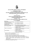
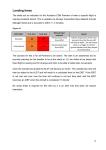
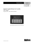
Configuration Software User Manual Gosafe Products Configuration Software User manual Configuration Software User Manual 1. General Note 1.1 The aim of this document Gosafe provide this document to describe the functions and operation environment of configuration software, with the aim of providing a better understanding of using scope and approaches of the configuration software for the OEM manufacture, What’s more, this document also provides necessary maintaining and updating information for products configuration software. 1.2Copyright This document is a confidential document, Gosafe reserves all rights to this document and the information contained herein. Any individual or organization is strictly prohibited to reproduction, use or disclosure to the third party without permission. Otherwise, we hold the right to investigate the legal responsibility. Company address: B301‐306, 69 Guangpu West Road, Science & Technology Park, Guangzhou, China. Tel: +86‐20‐66679696 E‐mail: [email protected] Website: www.gosafesystem.com 1.3Reference materials Product protocol and user manual Configuration Softwaree User Manual 2. SSoftware O Overview w 2.1SSoftware u usage The Intended au udiences of tthis documen nt are the distributor and d reseller of Gosafe prod ducts. o use the devvice, this doccument also provides a ffast configuraation tool. Who 2.2SSoftware o operation Thiss software caan be operateed on both tthe PC and th he compatible machine, it can be useed h Microsoft w windows (compatible win ndows 7), at first, you should decompress the with softw ware, and th hen click the Icons directly, then you can see the main menu of the software, you can configurre the devicee as you need. The speciffic is as follow wing: Configuration Softwaree User Manual 2.3SStructure o of the softtware The software consists of three parts, wh hich are configuration filee —config.xm ml; APN list file pnlist.txt and d executable file —G7707 7S.exe. —ap 2.4iinstallation n of the USSB driver ffor the softtware Pleaase connect o our device to o your computer, you will see the below picture: Then n choose thee options as tthe below piicture show you Configuration Softwaree User Manual Then n click the ‘n next’ button tto go to the below picture, and we choose as thee below pictu ure show w you. Please note that w when you are choosing the ‘Browse’ button, you should choo ose the configuration file folder. You should choose the configuratio on file folderr which has tthe “Anyytracking USSB.inf” document. Configuration Softwaree User Manual Then n press ‘nextt’ button, you will see the below pictture. Finaally the installlation is finissh and we geet the below w picture. Configuration Softwaree User Manual Notte: If yo ou have not d do the installlation of the USB driver, the device w will cannot bee connected tto yourr computer. 3. u user interfface overvview Once “G797S” iss started, and d connect to o the computter correctly,, the tool willl start up as wn in Figure 1. show —Figure 1— — 3.1 The tool iss composed of these tabs: 1. “Device”→””So ware”+””Hardware” 2. “Server”→”Main”+”SMSS Server”+”TTCP/UDP Upload” 3. Main”+”SMS FForwarding & & Shutcut Keey”+”Monito or & Commun nica on” “User”→”M 4. “Dynamic U Upload” Configuration Software User Manual 5. “Geo‐Fence”→”Main”+”Geo‐Fence setting” 6. “OBDII” 7. “Alarm”→”Se ng”+”Alarm Mask” 8. “Debug”→”Command”+”Debug” Chose the function you need, to read and write the parameter. When the parameter is not correct, it will show “Command error!” 3.2 “Communication” explanation: 1. “Comm ports”→COM10 means the device is connect to Port No. 10 ( computer can automatic identification); 2. “Device Model”→G797 Product model:G797;Click the button, can choose the model; 3. “Password “→ default password is“0123456789”(the only one password which can automatic login the configuration status). 4. Button :“Connect” means the device is connect with the computer, when the password is not the default one, need to input the correct one and then press “Connect” button, then the device can login the configuration status; 5. Button: “Disconnect” means cancel the device connects with the computer; 3.3 “Function” 1. “Import”: means import configuration files; first of all, there must be one export configuration file which was exported before. Can use “Export” to export the configuration files. 2. “Export”: means export configuration files, it can correctly export the configuration parameter, first of all, must choose “√”. The purpose is to select the option which needs to be exported. Otherwise the files will be empty (invalid configuration files). Notes: when import the file, the content must be same as the export one. When setting for the bulk order, no need to select all, just choose the one you need, to avoid the error reminder. 3. “Reset”: means to set the parameters to default configuration; Configuration Softwaree User Manual 4. “Restart”: m means to resttart the device; 5. 6. hich were chose. “Read All”: means to reaad all the parameters wh 7. which were chose. “Write All”: means to write all the parameters w select”√” heere, means to o choose all the function n,; 3.4 “Device in nfo” De evice Name:G G797 De evice ID: 358 86960422353 351 (Device IID) Haardware verssion:3.000 Hardware e version So oftware versiion:3.052 Softwaree version IM MEI: 3586960 042235351 “Internattional Mobilee Equipm ment Identityy” SIM M MCC:460 , MNC:00 “To judgee the device can read th he SIM card o or not” SIM M ID: 898600 0901911490 028638 The software contains eight setting pagees; there are ”All”, ”Read d” and ”Write e” button. 1. “All”: press “All”, to cho oose all the o optional thatt page have.。 a) For exaample: On “D Device” pagee, ”Software”” or ”Hardwaare” page, yo ou click “All””; it will sellect all the optional undeer the “Devicce”. 2. ”Read”: Can n only read tthe parameteer which were chose“√”,, click the “re ead” button, then you caan read the p parameter w which device w were set. 3. ”Write”: can only write the parameter which weere chose“√””, click the “w write” button, ou can write the parametter into the d device. and then yo Configuration Softwaree User Manual 4. D Device Configuratio on 4.1..1.Device e‐Software e Wheen read or w write the paraameter, the o operation staatus informaation will sho ow on the rigght of th he page. Pleaase see figurre 2. —Figure 2— — 1. Change PC C Config Passw word (OPW): The device ccontain OEM M password aand the default password iss 0123456789 9. This passw word can be changed by selecting this parameterr. It is recommended that do on’t change the OEM passsword. 2. Time Zone ((TZN): The deevice can be set for the ttime zone. Th his time zone e setting is o only for the userr. When userr receives thee SMS it will contain timee and this tim me will be same as what time zone set in n this parameeter. 3. Daylight‐Savving Time (DST): Set the daylight‐saving time according to thee actual situation. 4. AGP): Enablee disable A‐G GPS feature. Enable/Disaable A‐GPS (A Configuration Softwaree User Manual 5. Enable/Disaable Mileage (MGE): Enab ble disable m mileage calcu ulation feature. 6. Query/Set M Mileage (MG GR/MGS): The system c T an store the mileage of tthe vehicle which is 0 w when the traccker is just in nstalled and can add the future GPS m mileage automaticallly in it. And you can also o set the initiial mileage o on the trackeer. Please notte that the num mber we havve to enter h here is in metters. The deffault value iss 0. 7. Power Save Mode (PSM M): only when n the upload time is largeer than 15miins, device go oes into power save. 8. P): Setting the threshold. There are G GPS and GSM M two ways. Power Save Setting (PSP 9. ower is off, tthe device will Device Power Off (DPD): If enabled, when devicee external po working timee is up. Only for G717. power off affter extend w 4.1..2.Device e‐Hardwarre Configuration Software User Manual 1. Enable/Disable Movement Sensor (MOT): The system can enable disable the movement sensor. Note: The upload modes are depended on movement sensor. If the movement sensor is disabled the user will not receive “Move Alarm” and also the system will keep one upload mode. 2. Movement Sensor Setting (MTP): Vibrate duration is used when vehicle is in stop status and judge vehicle from stop to move. Stop duration is used to when vehicle is in moving status and judge vehicle from move to stop. The movement sensor parameters are to set the sensitivity of the movement sensor. Here we have three parameters Vibrate Threshold: Moving Last Time: This is time in seconds mean if the device moves for set time. Value range (1 ~ 255) Vibrate Duration: This number of movement in the set time. Value range (1~255) Stop Duration: This is time means if the vehicle stops for more than set time here will again send the move alarm to the user. If it stops less than set time here then it will not send the move alarm to user. Value range (1~255). 3. G‐Force Record (GRC): Device judge the data every 3 sec, and not all data will be judged. Judged number is depend on the “Judged Numbers”. 4. Immobilizer Output Method (IMS): For dynamic Immobilize, device will output one pulse every 10 second. 5. Immobilizer Output Voltage Level (IML): Most of the device is negative. 6. Serial Port Baud Rate (EPB): The device communication port baud rate can be set here. Click on the drop down menu to select the baud rate. Default is 9600 7. Serial Communication Protocol (EPS): when device connect to peripheral equipment, if choose “Protocol”, means device and equipment communicate each other by protocol. If choose “ Transparent”, means device only receive data and send to server. 8. Serial Port Data Setting (PKI): the data will be including the accompany info and sent through the select channel. The peripheral ID is the information which you set before. For example, set RFID as 2, and you select 2. The data will include the RFID information also. This only for G71. 9. FM Frequency (FMF): setting the FM Frequency same as the radio on car. Then can hear the voice through the radio. This only for G717. Configuration Softwaree User Manual 10. Ring Tone (TTON): settingg the ring ton ne and the m music. 11. Voice Volum me (AGN): settting the volume of the M Microphone and speakerr. 12. Enable/Disable Key Tonee (KTN): Enab ble/Disable K Key Tone. 13. Enable/Disable Key Lockk (KLK): Enable/Disable Key Lock. 14. Enable/Disable Vibrator(VIB): Enable e/Disable Vib brator. 4.2..1 Server‐M Main 1. APN List (AP PL): The APN list can be e edit by pressiing the Edit A APN button. It will open a text file whicch contain all the APN lisst if set country APN is no ot available iit can be add ded as follows: [ yyyy ] MNC=xx; APN N=xxxxxxxx; U USER NAME==xxxxxx; PW==xxxxxxx; MCC=xxx; M Configuration Software User Manual MCC=xxx; MNC=xx; APN=xxxxxxxx; USER NAME=xxxxxx; PW=xxxxxxx; yyyy is country name MCC & MNC can get from the GSM service provider or can find from this link http://en.wikipedia.org/wiki/Mobile_Network_Code# Note that every GSM service provider has its own MCC and MNC. If the MCC and MNC are not correct the device will not set the APN. 2. APN (APN): APN: access point name; USER NAME: this is the user name of the APN if there is no user name can leave this blank PW: This is the password for the APN. If there is no password for the APN can leave this blank In the above example there are two GSM operator added. If there are more operators then just add more lines with their APN details. 3. GPRS Sever IP Port (SIP): Insert the IP and Port which the software located. 4. GPRS Sever Domain (SDM): Insert the Domain which the software located. 5. Upload Data Select (ADM): It can select what data device will upload to the server. There are six options 6. Heart Beat Interval (HBI): This is for setting the heart beat data uploading interval. Note that the number is Minute. 7. Change TCP Channel To UDP Channel (SOM): when enable the original TCP channel will use UDP to send all the original TCP relate data. All the setting of this new UDP channel will be same command as old TCP channel. 8. Upload From Extend Flash (EFS): Device can save the data (save over flow of 1K RAM or save all data) into flash and send to server. The data will not be lost even device power off. Configuration Softwaree User Manual 4.2..2 Server‐SSMS Sever 1. Manager SM MS Sever No. (SSN): You ccan get this N NO. From yo our SIM card provider. Th his must be righ ht, or you can nnot get anyy messages from the device. 2. Manager SM MS Sever Upload Mode 0 0 (SSM0): By tthis you decide disable o or enable thee SMS upload mode0. Parame eter 1 G: GPS data: the meessage will tell you the lo ocation by sh howing you tthe longitudee and latiitude. S: Base station dataa: the messaage will tell you the location by showing you the b base station data. Parame eter 2 T: Text:: the location n datas’ form mat is text. Configuration Softwaree User Manual Parame eter 3 IIt is the interrval of uploading the SMS. The value can be 30~9 900S, 15~59M M, 1~240H. 3. Manager SM MS Sever Upload Mode 1 (SSM1): By tthis, disable or enable th he SMS uploaad mode0. 4.2..3 Server‐TTCP/UDP U Upload 1. TCP Upload Mode 0 (TPM M0): Enable and disable user upload mode0 Parame eter 1 G: GPS data: the GP PS data will b be uploaded to the user phone No. will be uploaaded to the u user phone N No. S: Base station dataa: the Base sstation data w Parame eter 2 Text: th he location’s format will be text. Configuration Software User Manual Hyperlink: the location’s format will be hyperlink. Parameter 3 Data upload interval and voice monitor interval can be set. The value is 30~900S, 15~59M, 1~240H. 2. TCP Upload Mode 1 (TPM1): Same explain as the user upload0. This another user upload mode to choose 3. TCP Upload Buffer (TUP): You can set the quantity of records in every packet. When the records reach what you set, the device will upload the data automatically by the TCP channel. Note you have to enable the TCP Upload Buffer firstly. The device will keep uploading automatically once it reach on certain percent of 1kb, like 30% by the TCP channel. 4. UDP Upload Mode 0 (UPM0): Same explanation like the TCP upload mode. The only difference is that the upload channel changes to UDP channel 5. UDP Upload Mode 1 (UPM1): Same explain as the user upload0. This another user upload mode to choose 6. UDP Upload Buffer (UUP): Same explain as the TCP Upload Buffer (TUP). 7. Upload By Distance (DIS): The device will keep uploading automatically once it reach on certain distance by the TCP channel. 8. Upload By Angle Change (TRN): Enable and disable the angle change alert 9. Harsh Acceleration‐GPS (SPD): Enable and disable the harsh acceleration‐GPS. Select the times and the speed. When the parameter get to the setting speed and for the setting times. It will send alarm to software. Configuration Softwaree User Manual 4.3..1 User‐Maain 1. User Phone No. (UNO): SSet the user phone No. Iff you want to o send some e command tto by the user phone, you haave to set th he same userr phone No.. the device b 2. User Passwo ord (UPW): SSet the user p password an nd confirm it.. When the u user needs to o send the com mmand to th he device, the password is the essenttial part of th he command d. For details, ssee the command list. 3. User Upload d Mode 0 (UU UM0): to sele ect the uploaad mode. Parame eter 1 G: GPS data: the meessage will tell you the lo ocation by sh howing you tthe longitudee and latiitude. S: Base station dataa: the messaage will tell you the location by showing you the b base station data. Configuration Software User Manual Parameter 2 T: Text: the location datas’ format is text. Parameter 3 It is the interval of uploading the SMS. The value can be 30~900S, 15~59M, 1~240H. 4. User Upload Mode 1 (UUM1): Same explain as the user upload0. This another user upload mode to choose 5. Hyperlink With GPS Data (URL0): This is the setting for the hyperlink which user receives if he set the W mode. The default setting is Google map link but this can be changed to specific map link like Bing, Yandex or open street map. And you have to give the setting parameters. And this one is for the GPS data 6. Hyperlink With Base Station Data (URL1): This is the setting for the hyperlink which user receives if he set the W mode. The default setting is nothing but this can be changed to specific format. And you have to give the setting parameters. And this one is for the LBS data. For details, see the protocol. Generally speaking, do not set this one 7. User Command Mask (UCM): This is used to allow which command the user can use. Configuration Softwaree User Manual 4.3..2 User‐SM MS Forward ding & Sho ortcut Key 1. SMS Forwarrding (SMT): Our device ccan transfer tthe SMS from m certain No o. to certain No. it is usually u used to set transferring tthe SMS from m the telecom mmunication n company tto the user, forr example, th he payment reminder SM MS. 2. Shortcut Keyy (USC): You can set shorrtcut for the commands o on this page, there are 1 10 shortcuts,each one corresponds w with differentt command. TThe specific corresponding parameter ccommand can also be savved in the cm md list of con nfig.xml file in advance. Configuration Softwaree User Manual 4.3..3 User‐Mo onitor & Communicaation 1. Enable/Disable Any Phone Call In (VO OI): When ch hoose enable e, any phonee can call in tthe device. 2. Voice Monittor NO. List (VML) (VMM): Only the vvoice monito or No. can get the call fro om the device th hat can call aautomatically when it geets voice mon nitor commaand. And onlyy when these numbers call the device,, the device can automattically pick up the call to let of the list “ ”, then aany phone No o. you monitorr. Once you sset any No. o can monitorr the device 3. Hotline NO. List (HOT): TThe Hotline N No. can achieeve two wayy communicaations with th he e you set anyy No. of the list “ ”, then any phone No. can device. Once achieve two o way commu unication witth the devicee. 4. Quick Dial N No. List (FCL):: Saved the n number in deevice and diaal to the num mber by key board/butto on operation. Configuration Softwaree User Manual 4.4 Dynamic U Upload 1. Shift To Uplo oad Mode 1 Condition Se elect: (DNU): You can sett Dynamic up pload mode 0 or mode1 for eeach status. TThere are sixx statuses to choose. If yo ou set the fro ont pages, th hat are the SMSS Server pagee, the TCP an nd UDP page and user page, with diffferent mode.. Then on thee corresponding status, iff you choose mode0, all tthe front thrree pages sett will work at mod de0. No ote: the conndition is thee three front pages modee have been set and enabbled. One off the selected conditio ons is meetin ng, then devvice shift to u upload modee1. Configuration Softwaree User Manual 4.5..1 Geo‐Fen nce‐Main 1. Geo‐Fence EEnable/Disab ble (GOF): On n the Geo‐fence page, yo ou can set en nable/disablee geo‐fence an nd user mask of geo‐fencce. We have total 28 Geo o‐fences can n store in thee device mem mory. Then yo ou can choosse some of th hem or all to o let them wo ork. If you choose it like the below picture, then only numb ber 8, 9,17,18 8,26 and 27 w will work. Th he others won’t work 2. User Geo‐Fe ence Enable//Disable (UFM M): This meaans you can cchoose on w which geo‐fen nce the user can n get the alarrm if there iss any alarm. 3. Geo‐Fence G Get Location Time (POI): waiting to o get the locaation more th han the settiing time, it will ssign out settting. Configuration Softwaree User Manual 4.5..2 Geo‐Fen nce‐Geo‐Fe ence Settin ng 1, Geo‐Fence SSetting: you ccan draw the e Geo‐fence here. Parame eter 1, Draw tyype: select the draw type, there aree round, recttangle and p polygon type. Parame eter 2, No.: name of the geeo‐fence. Parame eter 3, Type: th here are Geo o‐fence in, Geo‐fence out and In Or O Out. Select one of the alaarm statuses. Geo‐fence heere draws wh hich cannot b be shown on n the websitee. But can bee use Notes: the G also. Configuration Softwaree User Manual 4.6 OBDII 1. Fuel Coefficiient (OBP16)): To calculatte the fuel co onsumption, first should choose the fuel coefficient. 2. Initial Fuel C Consumption n (FCI): Only w when the fueel coefficientt is correct aand not emptty, this can be ccorrect. 3. Query Fuel C Consumption n (FUC): Check fuel consu umption, jusst for query, cannot be seet. 4. Vehicle Low Battery Alarrm Threshold d (OBA0): Seetting the thrreshold of the low batterry. 0~25.5 V; Du uration: the rrange is 0~25 55 second. Threshold: tthe range is 0 When the th hreshold reach to the settting parameeter and last for the setting duration,, device will send alarm to o software. 5. Engine Overr Heat (OBA1 1): Configuration Software User Manual Threshold: the range is ‐40~215℃, Duration range is 0~255 second. When the threshold reach to the setting parameter and last for the setting duration, device will send alarm to software. 6. Engine Over Revving (OBA2): Threshold: the range is 0~25.5KRPM, Duration range is 0~255 second. When the threshold reach to the setting parameter and last for the setting duration, device will send alarm to software. 7. OBD Data Upload Select (OBP): This one is for setting OBDII data uploading. It will decide which OBDII data can be uploaded. When you check your vehicle’s protocol, and you know which one is open by the vehicle manufacturer, you can just choose one of the 15 OBP data which have not been used for any OBDII data uploading, and then input the OBDII code you decide to upload. Click it like the below picture, then press the “write” button. In the future, you will get this OBDII data. Configuration Softwaree User Manual 4.7..1 Alarm‐SSetting 1. Enable/Disable Over‐Speeed Alarm (SSPO): Enable disable Over‐speed alarm feature. 2. Over‐Speed Parameter ((SOP): settingg the parameter of the o over‐speed alarm. 3. Enable/Disable Anti‐Jam mming Alarm (JAM): Enab ble and disab ble anti‐jamm ming mask. disable immo obilizing the car when an nti‐jamming. Enable and d 4. Harsh Acceleeration G‐force (HGV): Threshold: tthe range is 0 0~8.0G, Duraation range is 0.2~2 seco ond. W When the th hreshold reacch to the setting parameter and last ffor the settin ng duration, d device will se end alarm to o software. 5. Accident Detection G‐force (AGV): Configuration Softwaree User Manual Threshold: tthe range is 0 0~8.0G. Wheen the thresh hold reach to o the setting parameter, device will send alarm to o software. 6. Low Internal Battery Alaarm Thresholld (BAT): Wh hen the storaage batteriess of internal 37. batteries lesss than the seetting data, it will send aalarm. This iss only for G73 7. Arm Setting (ARM): setting the arm d data. 8. Enable/ Disaable Fiber Dissconnect Alaarm (FIB): Enable/ Disable Fiber Disco onnect Alarm m. 9. Fiber Parameter (FBP): this parameter is used to judge whether the fiberr is connecteed. 10. Enable/Disable Detach A Alarm (SAF): When enablle, the devicee will alarm o once the devvice was detacheed. 4.7..2 Alarm‐A Alarm Mask 1. With the below picture, that means Auto Clear aalarm will be sent to the user. Configuration Softwaree User Manual 2. With below picture, thatt means the Auto Clear aalarm will be sent to the SMS server o only. CP server, thee UDP serverr. It will not bee sent to the user, the TC 4.8..1 Debug‐C Command Inpu ut the command to set th he configurattion parameeter directly h here. Configuration Softwaree User Manual 4.8..2 Debug‐D Debug Read d the GPS an nd GSM original data herre.