1
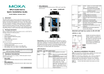
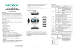
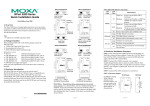
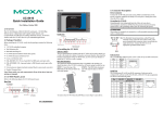
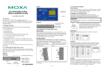
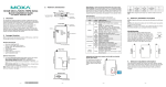
3. Hardware Introduction LED Indicators Reset Button—Press the Reset button continuously for 5 sec to load factory defaults: Use a pointed object, such as a straightened paper clip or toothpick, to press the reset button. This will cause the Ready LED to blink on and off. The factory defaults will be loaded once the Ready LED stops blinking (after about 5 seconds). At this point, you should release the reset button. LED Name LED Color LED Function PWR Red Power is being supplied to the power input. Steady on: Power is on and the NPort 6150 is booting up. Blinking: Indicates an IP conflict, or, the DHCP or BOOTP server did not respond properly or a relay output occurred. Check the Red relay output first. If after resolving the relay output the RDY LED is still blinking, then there is an IP conflict, or the Ready DHCP or BOOTP server did not respond properly. Steady on: Power is on and the NPort 6150 is functioning normally. Green Blinking: The device server has been located by the Administrator’s Location function. Power is off, or power error condition Off exists. Orange 10 Mbps Ethernet connection. Green 100 Mbps Ethernet connection Link Ethernet cable is disconnected, or has a Off short. Orange Serial port is receiving data. Green Serial port is transmitting data. P1 No data is being transmitted or received Off through the serial port. Serial port was opened by server side Green software. P1 in-use LED Serial port has not been opened by server Off side software. NPort 6150 Series Quick Installation Guide Fourth Edition, January 2013 1. Overview The NPort 6150 series of secure serial device servers provide reliable serial-to-Ethernet connectivity for a wide range of serial devices. The NPort 6150 supports TCP Server, TCP Client, UDP, and Pair-Connection operation modes to ensure the compatibility of network software. In addition, the NPort 6150 also supports Secure TCP Server, Secure TCP Client, Secure Pair-Connection, and Secure Real COM modes for security critical applications such as banking, telecom, access control and remote site management. 2. Package Checklist Before Installing the NPort 6150 secure device server, verify that the package contains the following items: • • • • • • 1 NPort 6150 Document & Software CD Quick Installation Guide (this guide) Power Adaptor Product Warranty Statement 2 Wall mount ears Optional Accessories • • • • DK-35A: DIN-Rail mounting kit (35 mm) DIN-Rail Power Supply CBL-RJ45M9-150: 8-pin RJ45 to male DB9 cable CBL-RJ45M25-150: 8-pin RJ45 to male DB25 cable NOTE: Please notify your sales representative if any of the above items are missing or damaged. Adjustable pull high/low resistor for RS-422/485 (150 KΩ or 1 KΩ) Jumpers are used to set the pull high/low resistors. The default is 150 KΩ. Short the jumpers to set this value to 1 KΩ. Do not use the KΩ setting with RS-232 mode, since doing so will degrade the RS-232 signals and shorten the communication distance. –1– P/N: 1802061500012 –2– –3– 4. Hardware Installation Procedure STEP 1: Connect the 12-48 VDC power adaptor to the NPort 6150 and then plug the power adaptor into a DC outlet. STEP 2: For first-time configuration, use a cross-over Ethernet cable to connect the NPort 6150 directly to your computer’s Ethernet cable. For connecting to a network, use a standard straight-through Ethernet cable to connect to a hub or switch. STEP 3: Connect the NPort 6150’s serial port to a serial device. Placement Options The NPort 6150 can be placed flat on a desktop or other horizontal surface. In addition, you may use the DIN-Rail or Wall Mount options, as illustrated below. Wall Mount Din Rail 5. Software Installation Information The Document & Software CD contains the User’s Manual, NPort Search Utility, and the PComm Lite Suite. Insert the CD and follow the on-screen instructions. Please refer to the User’s Manual for additional details on using the NPort Search Utility and PComm Lite. 6. Pin Assignments and Cable Wiring RS-232/422/485 Pin Assignment (male DB9) Pin RS-232 1 2 3 4 5 6 7 8 9 DCD RXD TXD DTR GND DSR RTS CTS --- RS-422 4-wire RS-485 TxD-(A) TxD+(B) RxD+(B) RxD-(A) GND --------- 2-wire RS-485 ----Data+(B) Data-(A) GND --------- –4– Two serial cables for connecting the NPort 6150 to a serial device can be purchased separately. The wiring diagrams for the two cables are shown below. 7. Specifications LAN Ethernet: 10/100 Mbps, RJ45 Protection: Built-in 1.5 KV magnetic isolation Serial No. of ports: 1 Interface: RS-232/422/485 (male DB9) Serial Communication Parameters Parity: None, Even, Odd, Space, Mark Data bits: 5, 6, 7, 8 Stop bit(s): 1, 1.5, 2 Flow control: RTS/CTS, XON/XOFF, DTR/DSR Speed: 50 bps to 921.6 Kbps Console Port: RS-232 (please see the User’s Manual for detailed operating instructions) Software Features Protocols: ICMP, IP, TCP, UDP, DHCP, BOOTP, Telnet, DNS, SNMP, HTTP, SMTP, HTTPS, SSL, SSH, PPPoE, RFC2217 Utilities: NPort Search Utility for Windows 98/ME/NT/2000/XP/2003/Vista/2008/XP x64/2003 x64/Vista x64/2008 x64 Security Protocols: DES/3DES/AES OS Driver Support: Windows Real COM drivers: Windows 95/98/ME/NT/2000/XP/2003/Vista/XP x64/2003 x64/Vista x64 Real TTY drivers: Linux 2.4 and 2.6 Fixed TTY drivers: SCO Unix, SCO OpenServer 5, OpenServer 6, UnixWare 7, UnixWare 2.1, SVR4.2, QNX 4.25, QNX 6, Solaris 10, FreeBSD 5, FreeBSD 6 Configuration: Web Console, Serial/Telnet Console, Windows utility Power Requirements Power input: 12 to 48 VDC Mechanical Specifications Material: Aluminum (1 mm) Environment Operating 0-55°C (32 to 131°F), 5 to 95% RH Temperature: Storage Temperature: -20 to 85°C (-4 to 185°F), 5 to 95%RH Regulatory Approvals EMC: FCC Class A, CE Class A Safety: UL, CUL, TUV www.moxa.com/support The Americas: Europe: Asia-Pacific: China: +1-714-528-6777 (toll-free: 1-888-669-2872) +49-89-3 70 03 99-0 +886-2-8919-1230 +86-21-5258-9955 (toll-free: 800-820-5036) 2008 Moxa Inc. All rights reserved. –5– –6–