1
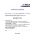
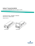
®
SIENNA SYSTEM
Switch to the future
Home control
ingeniously simple
Energy efficiency
Security
Lifestyle
SIENNA® SYSTEM
Switch to the future
SIENNA® SYSTEM
the new dimension in home automation
Ingeniously simple!!
• Easy to install and easy to reconfigure.
• Installation and configuration can be done with a screwdriver!
• No need for a PC or special software.
• Can be combined with all commercially available switches and power outlets.
• Can be retrofitted in all existing buildings.
• Simplifies wiring and eliminates detailed wiring plans.
• No additional cables or electromagnetic smog.
• Extremely reliable due to usage of LON technology.
Simply ingenious !!
SIENNA
Aktor
SIENNA
Sensor
The SIENNA® elements form a bus system consisting of sensors and actuators which use the in-house power lines as a
communication bus. The SIENNA® system revolutionizes wiring plans and places the intelligence of the system into
smart elements, located wherever they are needed in a home or a building.
The extremely simple installation process makes SIENNA® the ideal system not only for new buildings but also for renovations and retrofitting. No computers, no software, no special training is required -- all you need is a screwdriver and
you can install and configure the system.
2
Table of contents
SIENNA® SYSTEM
Switch to the future
Switching a single channel
SM1L / SM1B
SM1
AM1
AM1C
4
Sensor with one digital 230V input
Sensor with one digital input
Actuator with one switched output
Actuator with one switched output with current measurement
Switching multiple channels
SM2
SM2G
AM2L / AM2X
SM4 / SM8
6
Sensor with two digital inputs
Sensor with two digital inputs for switching multiple groups
Actuator with two switched outputs
Sensor with digital inputs for 4 to 8 channels
Switching with auxiliary functions
SAM1L
SAM2L
SAM1LT
SM1L+R
Sensor-Actuator with one switched output and one 230V input
2-Channel switch actuator with inputs
Sensor-Actuator with timer for delayed switching
Sensor with actuator-status display
Motor control
SM3
SM3G
AM2 / AMX2
SAM2
10
Sensor with three digital inputs for motor control
Sensor with three digital inputs for controlling motors in multiple groups
Actuator with two interlocked outputs for motor control
Sensor-Actuator for motor control
Dimmer / Toggle Actuators
AMDR
SAMDR
AMD10V
AM1A / AMXA
14
Controller for home automation and remote access
Thermostat
Wireless gateway inc. wireless remote for all SIENNA® actuators
Configuration
SIENNA® Professional
12
Actuator with one Triac output for dimming (Leading edge)
Sensor-Actuator with one input for dimming (Leading edge)
Actuator with 1-10V interface for dimming
Toggle actuator with two oppositely switched outputs
Home Automation
SIENNA® Home
SMTEMP / SAMTEMP
RFGS
8
16
Configuration software for SIENNA® modules.
Accessories
17
Technical Data
17
Address assignment
18
Applications
19
FAQ
23
3
Switching
single channels
SM1L / SM1B
SIENNA® SYSTEM
Switch to the future
SENSOR with 230V input
The SIENNA® SM1L sensor has one 230V input. The input can be connected to
a light switch or other switching elements (e.g. motion detector, thermostat etc..).
For optimized wiring, L, N can be extended via the additional terminals L', N.
Operational Modes:
Push (Each push triggers a switching action); On / Off; 3-Way.
Input:
One digital input (L, 1) with 230V / ~50Hz (Phase bridged to L’). Can also be used
with switches that have an integrated status lamp.
SM1L-ST01-H02 / SM1B-ST04-H02
EAN-Number: 4260194732019 / 101
SM1
SIENNA® SM1B for motion- detectors with continuous operation feature
(Continuos on; Continuous off).
SENSOR with 5V (internal) input
The SIENNA® SM1 sensor has one 5V input which can be connected to a
switch (On/Off, Off / On) or a push switch (dimmers & motors). Connection to
magnetic contacts or 0,08mm2 cables is also possible with the internal 5V input.
Potential free switching elements are required!
Operational Modes:
Push (Each push triggers a switching action); On / Off; Off / On.
SM1-ST06-H02
EAN-Number: 4260194732002
AM1
Input:
One digital input (0, 1) for connecting to a switch, push switch or magnetic
contact. 5V Input can also be used with 0,08mm2 connector cables. Max. cable
length to switch: 10m.
ACTUATOR for On / Off switching
The SIENNA® AM1 actuator can either be directly attached to an electrical
device or flush-mounted behind a power outlet. The SIENNA® AM1 actuator has
one relay-switched output for electrical devices with current ratings up to 10A.
Output:
L', N for connecting the electrical device. One single-pole relay rated at 10A to
switch L’.
N is bridged to the neutral of the power supply.
AM1-ST01-H01
EAN-Number: 4260194730008
AM1C
ACTUATOR for On / Off switching with current
measurement
Similar to the SIENNA® AM1 actuator but with additional current measurement
capability.
Visualization and recording of current usage with SIENNA® Professional.
AM1C-ST01-H01
EAN-Number: 4260194730039
4
Switching
single channels
SIENNA® SYSTEM
Switch to the future
Controlling a remote device from multiple points
/ AMDR
Controlling an additional device
Enable an exhaust fan via magnetic contact connected to sensor
5
Switching
multiple channels
SM2
SIENNA® SYSTEM
Switch to the future
SENSOR with two digital inputs
The SIENNA® SM2 sensor has two digital inputs (internal 5V) which can be
connected to one 2-gang switch or to two separate switches. This sensor
switches 2 actuators with addresses (g, e) and (g, e +1).
Potential free switching elements required!
Operational Modes:
Push (each push triggers a switching action); On / Off; Off / On;
Input:
Two digital (internal 5V) inputs (0, 1, 2) connecting to a 2-gang switch or to 2
switches.
SM2-ST05-H02
EAN-Number: 4260194732026
SM2G
SENSOR with digital inputs for switching multiple
groups
The SIENNA® SM2G sensor has two digital inputs (internal 5V) which can be
connected to one 2-gang switch or to two separate switches.This sensor
switches 2 groups (g, e) and (g + 1, e).
Potential free switching elements required!
Operational Modes:
Push (each push triggers a switching action); On / Off; Off / On;
SM2G-ST011-H02
EAN-Number: 4260194732057
AM2L / AM2X
Input:
Two digital (internal 5V) inputs (0, 1, 2) connecting to a 2-gang switch or to 2
switches.
ACTUATOR with two outputs
The SIENNA ® AM2L actuator can either be directly attached to an electrical
device or flush-mounted and is designed for switching two separate devices or
electrical circuits. AM2L has two relay-switched output for loads up to 5A.
Output:
L1, N, L2, N to the devices / electrical circuits: one relay each to switch up to
5A on L1, L2.
The output terminals N are bridged to the neutral of the power supply.
The SIENNA® AM2X actuator is similar to AM2L, but has potential free
outputs.
AM2L-ST02-H01 / AM2X-ST06-H01
EAN-Number: 4260194730060 / 107
Av
ai
la
bl
e
Se
pt
.2
01
0
SM4 / SM8
SENSOR with digital inputs for 4 to 8 channels
The SIENNA® SM4 Sensor has four digital inputs (internal 5V) which can be
connected to multiple switches. This sensor can switch up to 4 different
actuators.
Operational Modes:
Push (each push triggers a switching action); On / Off; Off / On;
Input:
Four digital (internal 5V) inputs (0, 1, 2, 3, 4) with flexible connecting wires which
can be connected to a single multiple-gang switch or to four separate switches.
SIENNA® SM8 sensor is similar to SM4, but has 8 digital inputs for 8 channels.
SM4-ST01-H01 / SM8-ST02-H01
EAN-Number: 4260194732118 / 25
6
SIENNA® SYSTEM
Switching
multiple channels
Switch to the future
Combining 1-channel and 2-channel modules:
g, e
g, e+1
Address assignment: g, e
Address assignment: g, e
Address assignment: g, e + 1
Sensor (2-channel) switches 2-channel
actuators and / or 1-channel actuators.
g, e
g, e +1
Address assignment: g, e
Address assignment: g, e + 1
Controlled via 1 sensor (2-channel)
and / or 2 sensors (1-channel).
Carrying forward a 3-Way contact
7
Switching with
auxiliary functions
SAM1L
SIENNA® SYSTEM
Switch to the future
SENSOR / ACTUATOR combination
SIENNA® SAM1L combines the SM1L sensor and AM1 actuator. SAM1L has
one 230V input and one switched output for loads up to 10A. The input can be
connected to a light switch or to other switching elements (e.g. motion detector,
thermostat etc..).
Operational modes:
Push (each push triggers a switching action), On / Off; 3-Way.
Input:
One digital input (L, 1) with 230V / ~50Hz. Can also be used with illuminated
switches.
SAM1L-ST01-H01
EAN-Number: 4260194734006
SAM2L
Output:
L', N connected to electrical device; One relay rated at 10A to switch L’.
N is bridged to the neutral of the power supply.
SENSOR / ACTUATOR combination with 2 channels
SIENNA® SAM2L has two relay-switched outputs for switching 2 separate
devices with current ratings up to 5A. The inputs with flexible wires can be
direclty connected to a 2-gang switch.
Operational modes:
Push (each push triggers a switching action), On / Off; 3-Way.
Input:
Three flexible wires for connecting to a switch.
SAM2L-ST03-H01
EAN-Number: 4260194734051
SAM1LT
Output:
Output terminals ▲ and ▼ for connecting to devices 1 and 2.
N is bridged to the neutral of the power supply
SENSOR / ACTUATOR combination with timer
SIENNA® SAM1LT includes a time-delayed switching functionality in addition to
the SAM1L module (e.g. for hallway lighting).
Delay time can be set within a range of 1 Min. to 2 Hrs.
Operational modes:
Push (each push triggers a switching action), On / Off; 3-Way.
Input:
One digital input (L, 1) with 230V / ~50Hz (Phase bridged to L’). Can also be used
with illuminated switches.
SAM1LT-ST03-H01
EAN-Number: 4260194734013
SM1L+R
Output:
L', N connected to electrical device; One relay rated at 10A to switch L’.
N is bridged to the neutral of the power supply.
SENSOR with actuator status display
The SIENNA® SM1L+R sensor has one 230V input like SM1L. One switched
230V output (max. 1A) indicates the status of the corresponding actuator.
Operational modes:
Push (each push triggers a switching action), On / Off; 3-Way.
Input:
One digital input (L, 1) with 230V / ~50Hz (Phase bridged to L’). Can also be used
with illuminated switches.
SM1LR-ST02-H01
EAN-Number: 4260194732095
Output:
Switched 230V output (L’, N) for displaying actuator status.
N is bridged to the neutral of the power supply.
8
SIENNA® SYSTEM
Switching with
auxiliary functions
Switch to the future
Additional control point for a device
Delayed switching (hallway lighting)
SAM1LT switches OFF all actuators after a preset
time interval.
Displaying actuator status via sensor
Display actuator status
Output of sensor SM1L+R switches
depending on actuator feedback and
displays the actuator status.
9
SIENNA® SYSTEM
Motor control &
central switching
SM3
SM3-ST02-H02
EAN-Number: 4260194732064
SM3G
Switch to the future
SENSOR with three digital inputs
The SIENNA® SM3 sensor has three digital inputs which can be connected to a
2-gang or 3-gang switch (Blind, Shutter: Up, Down, Stop). Centralized switching
functionality (Master-On, Master-Off) can also be implemented with SM3.
Potential free switching elements required!
Input:
Three binary (internal 5V) inputs (0, 1, 2, 3).
0: Common ground
1 / 2: Up (Master switch: On) / Down (Master switch: Off)
3: as defined by operational mode
Operational mode for input 3 (sliding switch):
Aus/Ein: Go up and stay blocked as long as input 3 is active (e.g. wind sensor).
Ein /Aus: Biased-off switch independent of actuator setting. Input 3 as in Aus/Ein
Taster: Additional stop functionality.
SENSOR for switching multiple groups
The SIENNA® SM3G sensor has three digital inputs which can be connected to
a 2-gang or 3-gang switch (Blind, Shutter: Up, Down, Stop). Centralized switching functionality (Master-On, Master-Off) can also be implemented with SM3G.
The SM3G switches actuators which have consecutive group addresses (e.g.
g = C switches actuators in groups C & D). The second group is switched with
a time delay of 1s.
Input:
SeeSM3.
SM3G-ST09-H02
EAN-Number: 4260194732071
AM2 / AMX2
Operational mode for input 3 (sliding switch):
See SM3.
AKTOR for motor control
The SIENNA® AM2 actuator can be directly mounted to a motor. AM2 has relayswitched output for motors with current ratings up to 3A. The outputs are
interlocked such that only one output can be active at any time. Run time can be
set with SIENNA® Professional (default run time is 120s.).
Output:
L1, N, L2, N for connecting to motor; one relay each to switch L1, L2 (Up,
Down) up to 5A. N is bridged to the neutral of the power supply.
AM2-ST01-H01 / AMX2-ST05-H01
EAN-Number: 4260194730053 / 114
SAM2
SAM2-ST01-H01
EAN-Number: 4260194734020
Operational modes:
Auto: Motor runs to end position; stops if switch is reactivated.
0:
Comfort switching for setting the slat angle of a sunblind / shutter
Man: Motor runs only when switch is activated.
SIENNA® AM2X actuator is similar to AM2, but with potential free outputs.
SENSOR / ACTUATOR combination for motor control
SIENNA® SAM2 combines the SM3 sensor and AM2 actuator in a single
module. SAM2 has 2 inputs for a blind-control switch and 2 interlocked outputs
motors with current ratings up to 3A. Run time can be set with SIENNA®
Professional (default run time is 120s.).
Input:
Three flexible wires for connecting to a switch.
Output:
▲, N, ▼ for connecting to motor; one relay each to switch ▲, ▼((Up, Down) up
to 5A. N is bridged to the neutral of the power supply
Operational modes:
0: Motor runs to end position; stops if switch is reactivated.
1: Comfort switching for setting the slat angle of a sunblind / shutter
2: Motor runs only when switch is activated.
10
Motor control &
central switching
SIENNA® SYSTEM
Switch to the future
Controlling sunblinds
Actuator / Motor control
Master switch (g, 0);
also for timers and weather stations
Control point with inputs / outputs
Panic switch / Master OFF (please refer to “Wiring plans” p. 20)
Address assignment: g, e = 0
Controls all elements with identical g.
Address assignment: g, e = 1
Address assignment: g, e =2
11
SIENNA® SYSTEM
Dimming
AMDR
AMD-ST04-H02
EAN-Number: 4260194730084
SAMDR
SAMDR-ST01-H01
EAN-Number: 4260194734037
AMD10V
Switch to the future
DIM-ACTUATOR, Leading edge
The SIENNA® AMDR actuator is designed to dim and / or switch incandescent
lamps and conventional transformers. The SIENNA® AMDR actuator has one triacswitched output for electrical devices up to 300W. Loads up to 150W are allowed
when the actuator is used with universal electronic transformers (leading and trailing
edge). In overload conditions, the actuator switches off automatically and can be
activated only after a predefined cooling phase (60s.).
Output:
L’, N for connecting to electrical device; One leading-edge output rated at 300W (cos
ø = 1) for dimming L’. N is bridged to the neutral of the power supply.
Operational modes:
0 / 1: R, L loads up to 300W (cos φ = 1) ; 150W (cos φ = 0,6)
2:
Universal electronic transformers upto 150W, Takes into account the min.
load requirements for universal transformers; Dims in the range from 30%
- 100%.
SENSOR / DIM-ACTUATOR combination, Leading edge
The SIENNA® SAMDR module combines the SM1L sensor and AMDR actuator
in a single module. SAMDR has a 230V input and a triac-switched output for
electrical devices up to 300W. Loads up to 150W are allowed when the actuator
is used with universal electronic transformers (leading and trailing edge). In
overload conditions, the actuator switches off automatically and can be activated
only after a predefined cooling phase (60s.).
Input:
One digital input (L, 1) with 230V / ~50Hz (Phase bridged to L’). Can also be used
with switches that integrate a indicator lamp
Output:
See SIENNA® AMDR.
Operational modes:
See SIENNA® AMDR.
DIM-ACTUATOR (1 - 10V)
The SIENNA® AMD10V actuator can be used with electronic ballasts or other
devices with a 1-10V interface to switch and / or dim these devices. The
SIENNA® AMD10V actuator has a current sink of max. 30 mA and can switch up
to 6 electronic ballasts connected in parallel.
Output:
Relay putput L’ for switching loads up to 10A.
N is bridged to the neutral of the power supply.
Output +, - is a 1-10V output for dimming the load. Output can have max. 30mA
when operated with several loads connected in parallel.
AMD10V-ST01-H01
EAN-Number: 4260194730091
AM1A / AMXA
ACTUATOR for alternate switching
The SIENNA® AM1A / AMXA actuator can either be directly attached to an
electrical device or flush-mounted behind a power outlet and is designed for
alternate switching The actuator has two outputs with oppositely switched relays
for electrical devices with current ratings up to 5A.
SIENNA® AM1A 230V output:
L1, N, L2, N to the devices / electrical circuits: L1 and L2 are oppositely switched
outputs up to 5A.
The output terminals N are bridged to the neutral of the power supply
AM1A-ST04-H01 / AMXA-ST04-H01
EAN-Number: 4260194730015 / 46
SIENNA® AMXA floating output:
X1, X, X2 are connected to the devices: X1 and X2 are oppositely switched
outputs with an external potential (X) up to 5A
12
SIENNA® SYSTEM
Dimming
Switch to the future
Dimmer control
(or SM1)
Regulating a motor (e.g. pump for a water fountain)
Please note that the pump needs to work together with a leading edge dimmer.
13
SIENNA® SYSTEM
Home automation
Switch to the future
THERMOSTAT
SMTEMP / SAMTEMP
SIENNA®
SMTEMP room temperature controller with temperature
sensor and continuos-action controller; compatible with front panels
from Berker, Gira, Merten, Jung und Peha.
Model SAMTEMP-ST02-H02 has additional switched outputs
(floating).
Input:
Potentiometer for setting the temperature.
Output:
SIENNA® SAMTMP-ST02-H02 with two switched outputs (2 oppositely switched potential free relays).
SMTEMP-ST01-H02 / SAMTEMP-ST02-H02
EAN-Number: 4260194732088 / 4044
SIENNA® RFGS
Wireless gateway inc.. wireless remote for all SIENNA® actuators
SIENNA® RFGS is a gateway for mapping wireless channels to SIENNA® powerline devices.
•
Plug-in module with RF-Receiver and SIENNA® Powerline output
•
Compatible with all Easywave RF-transmitters e.g. remote control or door-/window contacts.
•
32 configurable RF-Channels.
•
Configurable with a screwdriver.
•
Includes a 5-Channel remote control for usage with all SIENNA® actuators.
Technical Specifications (Gateway):
Frequency:........................................................ 868,30 MHz
Modulation:...................................................... FSK
Range(RF):..................................................... Outdoors: ca. 100 m; indoors: ca. 30 m
RF-Protocol:...................................................... Easywave; compatible with all Easywave
remotes (http:///www.eldat.de)
Channel Assignment:....................................... Maximum 32 RF-Channels
Power Supply:................................................... 230V~/50 Hz, power consumption max. 1.5W
Standby Power Consumption:........................ < 0,5W
Operating Temperature:................................... -25°C to +70°C
Safety Compliance:.......................................... EN 300 220-1 V1.3.1 (2000-09),
EN 300 220-3 V1.1.1 (2000-09)
Technical Specifications (Remote):
RF properties:................................................... See Gateway
RF-Channels:.................................................. 5 RF-Channels, with On / Up nnd
Up / Down buttons
Power Supply:................................................... 1 x 3V-Batteriy, CR2032
Operating Temperature:................................... -20°C bis +60°C
Safety Compliance:.......................................... EN 300 220-1 V1.3.1 (2000-09),
EN 300 220-3 V1.1.1 (2000-09)
RFGS-ST01-H01
EAN-Number: 4260194736017
14
Home automation
SIENNA® SYSTEM
Switch to the future
SIENNA® HOME
for Home Automation and Remote Access
SIENNA® Home is a Web-Server with an embedded application for controlling all SIENNA® devices
•
The SIENNA® Home Controller is always on and can control SIENNA® devices without an attached PC. A PC
with a web browser is required only while configuring the controller.
•
Scenarios and Schedules can easily be configured using a browser.
•
All components can be controlled and monitored remotely using a PC or a mobile phone with an web interface..
Technical Specifications:
Processor:........................................... RISC-CPU@400MHZ230V~/50Hz
Network Interface:.............................. 1 x 10/100 Ethernet Port
USB Port:............................................. 2 x USB.2.0
Powerline Interface:............................ LonWorks Powerline
Memory:............................................. SDRAM: 64 MB; FLASH: 64 MB
Console:............................................. Ethernet (RJ45) with DHCP Server
GUI:..................................................... Browser (PC, TV, Mobile phone)
Operating System:............................. Linux
Network Properties:........................... DHCP client, HTTP server, VPN
Applications:.....................................
Home Automation Framework, OSGi
Framework, JRE
SRV-HOME-ST01-H01
EAN-Number: 4260194736000
15
SIENNA® SYSTEM
Software
Switch to the future
SIENNA® Professional: for installation and configuration
SIENNA® Professional is a Windows program for installing and configuring all SIENNA® components and is designed for
system integrators. The PC based configuration can be used together with or as an alternative to the screwdriver based
configuration. This tool makes it very simple to change the configuration or to retrieve existing installations with a PC or a
laptop.
The USB port of the PC is used to couple to the communication bus i.e. the powerline. Any nearby power outlet can be used
to access the powerline. The coupling element PC/power plug is included with the software package.
System requirements, Laptop/PC:
Processor:.................................. Intel® Pentium® Processor
Operating System:..................... Windows XP Professional / Home, Vista (32-Bit), Windows 7 (32 Bit).
Hard disk:................................... 20 MB available space on hard disk
RAM:........................................... 64 MB RAM
Screen Resolution:.................... 1024 x 768
Interface:..................................... USB 1.1 or 2.0.
Technical Specifications (coupling element):
Technology:................................ Powerline communication in the B/C-Band (5kb/s) compliant
with FCC, CENELEC EN50065-1 and LONWORKS® protocol.
Bus coupling:............................. Power plug, 230V~/50Hz.
PC coupling:.............................. USB 1.1 or 2.0.
Operating Input Current:........... Power supply/Power plug: 250 mA maximum @ 18VDC.
USB: 50 mA maximum @ 5VDC.
Processor:.................................. Neuron processor integrated in the Powerline Smart Transceiver
PL 3120.
Operating temperature:............. -25°C to +70°C.
Safety compliance:.................... CE, EN55022 Class B, EN55024, ETSI300 019-2-3 T3.2, TÜV
EN60950.
SW-PROF-ST01-H02
EAN-Number: 4260194736048
16
SIENNA® SYSTEM
Accessories
DIN-G
Switch to the future
DIN-Rail Housing
DIN-rail housing for all SIENNA® flush-mounted modules.
Housing corresponds to DIN 43 880, size 1. Simple and quick assembly by
locking onto DIN-rails EN 60 715 TH 35. Base part with fixing towers. Top part
with ventilation slots. Vertical and horizontal guides for additional PCBs.
Locking lid for protecting the display and operating elements.
Model:
With perforations for cable feeds.
Package includes:
1 base with locking clip, 1 top cover
DING-H01
EAN-Number: 4260194737007
Technical Specs. (SIENNA® flush-mounted modules):
Technology:..................................... Perilune communication in the Backbone (5Kb/s) compliant with FCC, CENELEC
EN50065-1 and LONWORKS® - Protocol.
Power Supply:.................................. 230V~/50Hz, Power consumption 0.5W..1.5W via L, N connectors plus attached device.
Processor:........................................ Neuron-Processor integrated in Powerline Smart Transciever PL 3170.
Connectors:..................................... 0.08mm2 - 1.5mm2 for all connecting cables.
Operating Temperature:.................. -25°C to +70°C.
Voltage Surge Protection:.............. Varistor.
Standby Power Consumption:....... < 0,5W.
Range:.............................................. 300m connection length over all 3 phases; up to 2km on a single Phase.*
Safety Compliance:......................... CE, EN60669, EN50065-1.
*Differences in connection length can occur due to presence of other electrical elements (e.g. ground fault circuit interrupter).
Dimensions:
17
SIENNA® SYSTEM
Address Assignment
Switch to the future
All SIENNA® elements have two rotary switches, each with 16 positions, for address
assignment.
•
•
•
The first rotary switch sets the group address g to an alphabetic value (A, B, ..., P).
The second rotary switch sets the element address e to a numerical value (0, 1, ..., 15).
Arbitrary many elements can have identical g and e: All elements with identical (g, e) switch simultaneously.
Group address g indicates a particular group
•
E.g. all sunblinds have identical g, different e.
Element address e
•
•
Sensors with e = 0 control all actuators with identical g regardless of e (e.g. centralized control of sunblinds).
e = 0 iis a master switch; e.g. sensor connected to wind detector has the address (g, e = 0): this sensor controls all sunblinds
with identical g and arbitrary e.
Scheme: 3-Way switching
Arbitrary many sensors and actuators can have identical addresses. In this case each sensor controls all actuators.
E.g.: Each of the 3 sensors switches 2 actuators:
Switch
(g, e = 1) S
Appliance
A (g, e = 1)
(g, e = 1) S
A (g, e = 1)
(g, e = 1) S
Scheme: Master Switch
The address g, e = 0 defines a sensor to be a master switch. This sensor controls all actuators with identical g.
Note: The address e = 0 defines the master switch to be a On / Off switch regardless of the position of the sliding
switch. This implies that for a push switch, one position is defined as “ON” and the other as “OFF”.
Switch
Appliance
(g, e = 1) S1
A1 (g, e = 1)
(g, e = 2) S2
A2 (g, e = 2)
A2 (g, e = 2)
Master Switch
S0
(g, e = 0)
(g, e = 3) S3
A3 (g, e = 3)
(g, e = 3) S3
18
Solutions
SIENNA® SYSTEM
Switch to the future
1. Disable / Enable exhaust fan(s) via window contact
Installing a fireplace in an apartment is often associated with implementation of additional safety measures e.g. one needs to
ensure that an adequate supply of fresh air is always available. In most situations this implies that the exhaust fans in the
apartment can only be operated when the windows are open. SIENNA® offers a solution which can be retrofitted in existing
homes. A SIENNA® sensor attached to a magnetic contact at the window and actuators attached to the exhaust fans - this
makes the exhaust fans operational only when the window is open.
- SIENNA® SM1 with 5V input connected to window contact.
- SIENNA® AM1 disconnects power supply to exhaust fan(s).
2. Disable / Enable exhaust fans via boiler unit
Similar to fireplaces the simultaneous operation of a boiler unit and exhaust fans in an apartment can lead to dangerous
situations. E.g. the exhaust fans drawing in the exhaust fumes from the boiler into the apartment can result in a life threatening situation. SIENNA ® offers a solution which can be retrofitted in existing homes. A SIENNA ® sensor connected to the
output of the boiler and actuators attached to the exhaust fans - this disables the exhaust fans until the boiler is turned on.
- SIENNA® SM1L connected to 230V output of boiler unit.
- SIENNA® AM1 disconnects power supply to exhaust fan(s).
19
Solutions
SIENNA® SYSTEM
Switch to the future
3. Temperature control: Floor heating
SIENNA® offers a solution for regulating the temperature in each room separately--a solution that can be retrofitted in existing
buildings. SIENNA ® sensors with conventional thermostats are installed at an appropriate place in each room and SIENNA ®
actuators are connected to the appropriate heating valves. Each thermostat can now control the corresponding heating valve and
regulate the floor heating individually in each room. A measure of extra comfort that not only saves on heating bills but also
contributes towards a greener world.
- SIENNA® SM1L connected to thermostat output..
- SIENNA® AM1 switches heating valve.
4. Panic switch/ Master-OFF
SIENNA® allows one to easily retrofit a panic switch in existing homes. SIENNA® sensors connected to the existing light switches
and one central sensor is sufficient to activate the panic switch feature. If necessary the shades / blinds can also be raised when
the lights are switched on. With SIENNA® and with minimum effort one can easily enhance security and sleep peacefully at night.
- Master switch (SIENNA® SM3) Push switch connected to input 1 switches ON all actuators (Panic switch).
- Master switch (SIENNA® SM3) Push switch connected to input 2 switches OFF all actuators (Master-OFF).
- SIENNA® SM3 with a push switch connected to input 1 (Address = 0).
- SIENNA® SM3 with Master_OFF switch connected to input 2.
- SIENNA® AM1 / AM2L actuators with address = 1, 2, 3, 4, ...... etc.. are switched ON via the panic switch.
20
Solutions
SIENNA® SYSTEM
Switch to the future
5. Hot water supply
New and old homes both waste large amounts of energy when hot water is supplied to the whole house. In order for the hot
water to be readily available throughout the house, a circulation pump distributes hot water through pipes either continuously
or on a timed basis (e.g. 14 hours a day). This results in a significant, and completely unnecessary, waste of energy. It is
possible, however, to save about 30% of the hot water bill by starting the circulation pump only on demand, i.e. at the
moment hot water is needed at a certain tap
SIENNA® offers exactly this solution which can be retrofitted in existing homes. SIENNA® sensors, connected to standard
switches near the hot water taps, start the circulation pump only on demand. A SIENNA® actuator with a timer function lets
the circulation pump run just long enough to provide hot water at all the taps--typically less than a minute. Approx. 30-40s
after pushing the switch, hot water is available at the taps -- an easy way to save money and be eco friendly at the same
time.
- SIENNA® SM1L+R connected to wall-switch in the bathroom / kitchen -- the indicator lamp is on when the circulation pump is on.
- SIENNA® SAM1LT to control the circulation pump.
6. Motion detectors and indoor lighting
In the 70s motion detectors connected to the outdoor / garden lights were a standard way of preventing intruders from breaking in to empty homes. Nowadays this offers minimal protection against intruders and advanced features such as presence
simulation are necessary to effectively prevent break-ins. But how does one retrofit a presence simulation mechanism in an
existing home without expensive remodelling?
SIENNA® offers a solution which can easily be retrofitted in existing homes. All you need is a SIENNA® sensor connected to
the motion detector triggering the outdoor lighting and a SIENNA® actuator connected to a lamp inside the house. As soon
as the motion detector is triggered, it switches on a light inside the house -- an ingeniously simple way of simulating
presence in the home.
- SIENNA® SM1B or SM1L connected to the output of the motion /occupancy detector.
- SIENNA® AM1 connected to an indoor light.
21
Solutions
SIENNA® SYSTEM
Switch to the future
7. Room temperature control via a mobile phone
SIENNA® Home offers the possibility to control and monitor the heating, lighting etc. at home from anywhere and at anytime --and this can be retrofitted in all existing homes. The SIENNA® Home Server can be used to remotely access the electrical
devices at home via the internet. E.g., the room temperature can be remotely controlled using a mobile phone so that one
comes back from work to a warm and cosy home without wasting energy throughout the day--a feature that is convenient and at
the same time contributes towards a greener world.
- SIENNA® SMTEMP functions as the thermostat for regulating room temperature.
- SIENNA® AM1 switches the heating valve.
- SIENNA® Home for remote access
8. Scenes and Schedules
Scenes and schedules that control the lighting / heating / motorized blinds or other electrical appliances in a home provide
comfort and convenience, help save energy and are an important part of an enhanced lifestyle. In homes using conventional
electrical wiring it can be a real challenge if not impossible to implement these additional features without expensive remodelling.
SIENNA® offers a very simple solution
- a solution that can be retrofitted in all
existing homes.
The SIENNA ® Home Server makes it
possible to integrate any SIENNA ®
actuator into a scene. These scenes
can then be run individually or as part
of a schedule via the SIENNA® Home
Server. The homeowner can create
individual scenes / schedules that turn
lights on and off, adjust lighting levels
or open and close the blinds to create
the ideal mood for television viewing,
entertaining around the dinner table or
outdoor living. Another advantage of
living in a smart home!
- SIENNA® Home for defining and running scenes and schedules.
- SIENNA® modules for controlling the devices.
22
FAQ
SIENNA® SYSTEM
Switch to the future
• How does SIENNA® work?
SIENNA® sensors and actuators use the 230V powerline as a communication bus. The components can communicate over all
3 phases without any phase couplers or other central units. Any sensor can control any actuator within a building independent
of the actual electrical wiring. This combines the flexibility of wireless system with the reliability of a wired system.
• What is the range of the SIENNA® components?
The range is typically 300m cable length between the sensor and actuator independent of the ac-tual phase. The components do
not require additional phase couplers or frequency filters. A three-phase current cable (typically connecting the electricity meter
and power distributor or the connection to the cooking range) is sufficient for the phase coupling. In cases where the sensor and
actuator are on the same phase then the range extends upto approx. 2 km.
• Why does SIENNA® not require phase couplers?
SIENNA® components communicate via the powerline and this communication works over all 3 phases without the use of
additional phase couplers. A three-phase current cable (typically connecting the electricity meter and power distributor or the
connection to the cooking range) is sufficient for the phase coupling.
• Why does SIENNA® not require frequency filters?
During installation the SIENNA® components generate a domain (or building) address via a paten-ted process. As a result
neighboring buildings are logically separated from each other preventing any interference
• How many SIENNA® nodes can you install in a single building?
Up to 200 SIENNA® nodes can be installed in a single building. In case the no. of nodes is greater than 200, a slight delay may
be observed during execution of switching commands.
• Is SIENNA® compatible with other bus systems?
SIENNA® uses the LON Standard and is compatible with other LonWorks based systems. Echelon's LonWorks is a ISO/IECand ANSI-compliant platform that enables some of the world's most advanced control and energy management applications.
Normally LonWorks is used for commercial buildings and for big projects e.g. Munich Airport, the Reichstag in Berlin, the new
trade fair center in Stuttgart. etc. SIENNA® is the first system that offers LonWorks based products for residential buildings.
Troubleshooting
• An actuator does not respond to commands from the sensor.
In most cases the addresses (rotary switches) are not identical.
Solution:
The addresses can be changed / corrected via the rotary switches. No reset is necessary !
• A sensor with a 230V input does not switch reliably.
The sensor has an high input resistance connected to the 230V input "1". For cable lengths > 10m between the switch and
the input, it may occur that the voltage at the connecting wire is not completely reduced to ground-- this results in the sensor
not responding correctly.
Solution:
A load module connected to the sensor between the connecting wire (Input "1") and ground reduces the voltage at the input
so that the sensor can function correctly.
• The motors attached to the motor-actuators do not run smoothly.
The sensors used for motor control have low-voltage inputs and they can only be connected to potential-free switching elements.
Outputs (e.g. timers) that are not potential-free have to be made potential-free (e.g. by using a interposing relay). If the 230V
output is directly connected to the sensor inputs, the sensor will see a zero-crossing every 10 msec. and will try to start and stop
the motor with the mains frequency.
Solution:
Connect the sensor inputs to potential-free switching elements.
• The actuator and the sensor do not communicate with each other even though they have identical addresses.
The SIENNA® modules generate a domain / area address during the installation process (see section on "Installation" in the
user manual) Different domain addresses logically separate neighboring buildings / areas from one another. If the modules are
configured in a sequence and not all together, different domain addresses are generated and the modules do not communicate
with each other.
Solution:
Reset all modules by using the RESET button and then configure all modules in a single installation process (see section on
"Installation" in the user manual).
23
Secyourit GmbH
THE HOME CONTROL COMPANY
Secyourit GmbH
Auenstr. 100
80469 Munich
Germany
Tel.: +49 89 384 66 481
January 2010
Fax: +49 89 724 300 99
Email: [email protected]
Web: www.secyourit.com