1
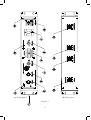
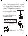
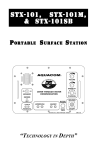
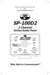
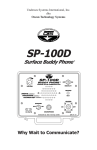
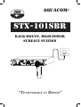
Aquacom®
STX-101SBR
Rack-Mount, High-Power
Surface Station
“Technology in Depth”
- NOTICE This manual and the information contained herein are provided for use as a maintenance and operation guide. No license or rights to manufacture, produce, and/
or sell either the manual or articles described herein are given. Undersea Systems
International, Inc., dba Ocean Technology Systems, reserves the right to change
specifications without notice. It is recommended that all users read and fully understand this manual before using the STX-101SBR.
All statements, technical information, and recommendations herein are based on
tests we believe to be reliable, but the accuracy or completeness thereof is not guaranteed; and the following is made in lieu of all warranties, expressed or implied,
including the implied warranties of merchantability and fitness for purpose: Seller’s
and Manufacturer’s only obligation shall be to replace such quantity of the product
proved to be defective. Before using, the user shall determine the suitability of the
product for intended use, and the user assumes all risk and liability whatsoever in
connection therewith. Neither Seller nor Manufacturer shall be liable either in tort
or in contract for any loss or damage—direct, incidental, or consequential—arising
from the use of or the inability to use the product. No statement or recommendation not contained herein shall have any force or effect unless it is in an agreement
signed by officers of the Seller and Manufacturer.
- IMPORTANT SAFETY NOTICE (Please read before using product.)
It is absolutely essential that all operators are properly trained and equipped
and fully understand this user’s manual before attempting to use the Aquacom® STX-101SBR.
While the STX-101SBR provides good underwater communications, it does
not change or eliminate the potential hazards of diving!
Refer to the Library page of our Web site, www.otscomm.com, for a list of
any changes made to this manual since its publication.
Copyright © 2010 by Undersea Systems International, Inc., dba
Ocean Technology Systems. All rights reserved.
Specifications subject to change without prior notice.
i
506113-000 (C)
TABLE OF CONTENTS
Section 1: Introduction .........................................................................1
1.1General...................................................................................1
1.2Features..................................................................................1
1.3
Specifications.........................................................................2
Section 2: Functions ..............................................................................3
Section 3: Installation ...........................................................................5
3.1
Mechanical Installation..........................................................5
3.2
Power Input Connection........................................................5
3.3
Microphone or Headset Connection......................................5
3.4
Remote Speaker Connection..................................................5
3.5
Record-Out Connection.........................................................6
3.6
Transducer Installation...........................................................6
3.6.1 Electrical Connection of the Transducer.....................6
3.6.2 Transducer Placement.................................................7
Section 4: Operation .............................................................................8
4.1Adjustments...........................................................................8
4.1.1 Power and Volume Control.........................................8
4.1.2 Squelch Control...........................................................8
4.1.3 Channel Selection.......................................................8
4.2Reception...............................................................................8
4.3Transmission..........................................................................9
4.4
Recording Communications...................................................9
4.5
Helpful Hints and Tips...........................................................9
Section 5: Maintenance .......................................................................10
Section 6: Troubleshooting .................................................................11
Limited Warranty ...............................................................................13
ii
SECTION 1
INTRODUCTION
1.1GENERAL
Congratulations! You have purchased one of the finest, state-of-the-art underwater
communication systems available. The Aquacom® STX-101SBR is a compact,
ultrasonic, single sideband transceiver designed to provide through-water communications for a surface vessel or submarine with another vessel, divers, or a
shore station. The STX series employs digital signal processing techniques,which
ensure the highest performance possible.
The STX-101SBR is an ultrasonic, through-water communication system. It must be
operated using water as the transmission medium. You will be able to communicate
with all diver transceivers, surface stations, and other communications units on the
same frequency and within range. When you speak into the microphone, your voice
is sent out in an omnidirectional pattern via the transducer to the other transceivers.
The transducer is the antenna that both sends and receives signals.
For user-friendly performance, the STX-101SBR offers many useful features, such
as dual channels, front-panel squelch control, a heavy-duty panel speaker, recordout capability, connection for a remote speaker, simple rack installation, and much
more. In all, the STX-101SBR rack-mount surface station is second to none!
1.2FEATURES
The Aquacom® STX-101SBR is equipped with two channels, either 8.0875 KHz
upper sideband (USB) (Channel A) and 11 KHz lower sideband (LSB) (Ch. B),
or 25 KHz USB (Ch. A) and 32.768 KHz USB (Ch. B)—depending on whether
it is the low-frequency or high-frequency version. It is a high-power surface station designed for through-water (wireless) communication with other receivers or
transceivers operating at the same frequency. External 24-volt DC power is applied
through a 2-pin military-style (MS) connector. The system includes a high-quality
hand-held microphone and an external transducer for transmission and reception.
The significant differences between the STX-101SBR and its sister product, the
STX-101SB, are the following:
STX-101SBR
STX-101SB
Number of channels:2 1
Design:
Rack mount
Portable
Power source:
24 VDC, external
12 VDC, internal
battery or external
1
1.3SPECIFICATIONS
Transmitter output power (nominal): 8/11 KHz version: 70 watts PEP
25/33 KHz version: 70 watts PEP
Audio output to speaker:
6 watts
Modulation:
Single sideband with no carrier
Operating channels :
Low-frequency version
Ch. A: 8.0875 KHz USB2 (NATO)
Ch. B: 11 KHz LSB
High-frequency version
Ch. A: 25 KHz USB
Ch. B: 32.768 KHz USB
Power:
24 volts DC at a minimum of 10 amps
Transducer:
Piezoelectric type, oil filled
Receiver sensitivity:
120 dBv for 10 dB S/N
Automatic Gain Control (AGC):
Greater than 120 dBv
1
Transmitter speech freq. bandwidth: 300–3500 Hz
Activation (on/off):
Volume switch on front panel
Volume:
User adjustable from the front panel
Squelch:
User adjustable from the front panel
Microphone:
Hand-held, dynamic, 100- to 1000-ohm
impedance
Microphone/headset jack:
6-pin MS connector on front panel
Record output jack:
3-pin military style (MS) connector, line level
Housing:
19-inch rack-mount enclosure
Housing dimensions:
Height:
Width:
Depth:
3.49 inches
18.3 inches between centers of mounting holes
16.7 inches case width
8.00 inches (mounting brackets)
1. Custom frequencies can also be ordered. Contact OTS or your local dealer.
2. “USB” is upper sideband; “LSB” is lower sideband.
2
SECTION 2
FUNCTIONS
See Figure 1 throughout.
1. MOUNTING BRACKET: One of two brackets for mounting the unit into a
rack. The brackets include holes for securing the unit with hardware.
2. On/off and volume switch: This switch is used to turn on and off the
unit’s power and to adjust the listening volume from the front-panel speaker,
a remote speaker, or a headset.
3. SQUELCH CONTROL: The squelch control helps to suppress background
noise created by sea creatures (e.g., snapping shrimp and croakers) and human
activity (e.g., boat engines).
4. SPEAKER SWITCH: This toggle switch is used to turn the front-panel speaker
on and off.
5. SPEAKER: The heavy-duty front panel speaker.
6. CHANNEL SWITCH: The channel selection toggle switch is used to select
the channel used for transmission and reception. Two channels are available,
A and B (the frequencies depend on the product version you have purchased;
see “operating channels” in Section 1.3, Specifications).
7. MICROPHONE HOLDER: A clip used to secure the hand-held microphone
when not in use.
8. MICROPHONE/HEADSET CONNECTOR: A 6-conductor military-style
(MS) receptacle for a hand-held microphone (model number HHM-STX-101SBR, included with the communications unit) or headset with boom microphone (model number THB-STX-101SBR, optional and sold separately).
9. HANDLE: One of two front-panel handles for easily moving the unit.
10. TRANSMIT INDICATOR: This red LED indicator lights up when the unit is
transmitting.
11. POWER INDICATOR: This green LED indicator lights up when the unit’s
power is on.
12. POWER CONNECTOR: A 2-conductor military-style (MS) receptacle for 24
volts DC power input at a minimum of 10 amps.
13. REMOTE SPEAKER CONNECTOR: A 4-conductor military style (MS)
receptacle for an external, remote speaker.
14. RECORD-OUT CONNECTOR: A 3-conductor military style (MS) receptacle
for connecting a recording device. It supplies “line-level” signal output.
15. TRANSDUCER CONNECTOR: A 6-conductor military-style (MS) receptacle
for the transducer (model no. TA-8STX101SBR or TA-25STX101SBR).
3
(A) Front panel
(B) Rear panel
Figure 1
4
SECTION 3
INSTALLATION
Installation of the STX-101SBR is a fairly simple process. The installation steps for
the transducer may vary according to the setup of your communications system, so
adapt the transducer installation instructions provided here as necessary.
3.1
MECHANICAL INSTALLATION
Install the communications unit into a rack of standard width (19 inches) for electronic equipment. Use four #10-32, 1/2-inch panhead machine screws (not supplied)
to secure the unit’s mounting bracket (Fig. 1, #1) to the rack.
3.2
POWER INPUT CONNECTION
The power required for the STX-101SBR is 24 volts direct current at 10 amperes
applied through the power jack (Fig. 1, #12).* The unit will draw approximately
8 amperes peak during transmission.
The mating (male) connector for the external power connection is a supplied
2-pin military-style connector, standard industry part number MS3106F14S-9P.
(Replacement connectors can be ordered from OTS as part number 211021-000).
The power input connections are as follows:
24-volt positive input on MS:
24-volt negative input on MS:
3.3
Connector on pin A
Connector on pin B
MICROPHONE OR HEADSET CONNECTION
With the STX-101SBR is provided the HHM-STX-101SBR hand-held, noisecancelling microphone for sound transmission. Also available (sold separately) is the
THB-STX-101SBR headset, a high-quality, dual-ear headset for hearing received
communications with reduced interference from surrounding sounds. The headset
also has a boom microphone for transmission of voice communications.
Simply connect the hand-held microphone (HHM-STX-101SBR, provided) or the
THB-STX-101SBR headset (sold separately) to the unit’s “mic/headset” jack (Fig.
1, #8), and it is ready for operation.
3.4
REMOTE SPEAKER CONNECTION
If you will be using a remote speaker, you will need to use a 4-pin male military-style
connector, standard industry part number MS3106A14S-2P; one is supplied with
the STX-101SBR for your convenience. (Replacement connectors can be ordered
*A low-power version is available on request with a 14.7-volt, 10-amp power supply. Contact
OTS or your local dealer.
5
from Ocean Technology Systems as OTS part number 211020-000.) The correct
wiring configuration for the remote speaker connector is as follows:
Remote speaker signal + on MS:
Remote speaker return on MS:
Connector on pin C
Connector on pin B
To use the remote speaker, just plug the speaker connector into the “remote speaker”
jack (Fig. 1, #13).
3.5
RECORD-OUT CONNECTION
If you wish to record the communications through a direct line, connect the record
cable via the supplied 3-pin male military-style connector to the “record out” jack
(Fig. 1, #14) on the STX-101SBR unit. (The connector’s standard industry part
number is MS3106A14S-1P, and replacements are available from OTS as part
number 211015-000.) The wiring connections for the plug are as follows:
Record-out signal + on MS:
Record-out signal return on MS:
Connector on pin A
Connector on pin B
Plug the output plug of the record cable into the recorder’s line-in jack.
3.6
TRANSDUCER INSTALLATION
With the unit is provided a transducer assembly (the TA-8STX101SBR for the
8/11-KHz version or the TA-25STX101SBR for the 25/33-KHz version) with a
6-pin MS-type plug for connection to the STX-101SBR (Fig. 1, #15).
3.6.1 ELECTRICAL CONNECTION OF THE TRANSDUCER: If the transducer will be connected to a bulkhead penetrator or connector, the MS connector
must be removed from the transducer cable and the cable spliced to the connector
you will use. Follow these wiring instructions (a proper connection is critical for
the unit to function):
1. Connect the white leads together.
2. Connect the black leads and the shield together at the splice between the
transducer cable and the cable with the MS connector.
3. For the MS connections, pins A and B are shorted together and connected to
the black leads and shield of the transducer cable. The other white cable lead
is connected to pins E and F. Pins E and F also are shorted together.
The following is a summary of the wiring connections:
Transducer signal + on MS:
Connector on pins E & F
Transducer signal return (shield) on MS: Connector on pin B
3.6.2
TRANSDUCER PLACEMENT: Mounting holes are provided on the
6
transducer (Figure 2) for securing it to one or more brackets that you can fabricate
to your required specifications (the bracket materials and all hardware should be
type 304 or 316 stainless steel to prevent salt-water corrosion). The holes contain
the bolts for securing the transducer cage to your bracket; if longer bolts are needed
to accommodate the bracket thickness, substitute bolts (stainless streel, type 304
or 316) long enough to secure the bracket to the transducer base plate but not so
long as to bottom out on the base plate. (Note: If the transducer is supplied with
urethane covering the holes, carefully remove the urethane with an adequate tool.)
Suggestions for placement of the transducer are provided in Figure 3.
If you are going to suspend the transducer into the water, do not hang the weight of
the transducer on the cable (doing so would strain
the cable). Instead, fabricate and attach brackets to
the transducer, tie a rope to the cable, and configure
the rope with a service loop to hold the transducer’s
weight (see Figure 3A for our suggestion).
If instead you will secure the transducer onto a submarine or other vessel, fabricate a bracket similar to
the one shown in Figure 3B (but with a configuration appropriate to your use), using the bolt pattern
illustrated in Figure 2 as a guide.
Table 1: Mounting Hole Configuration (Fig. 2)
Transducer Model # Holes Circle Diameter
TA-8STX101SBR6
Ø2.875
TA-25STX101SBR3
Ø1.50
(A) Suspended
Screw 1/4-20 (type 304 or
316 stainless steel) equally
spaced on bolt circle per
Table 1.
Figure 2: Example of
transducer mounting
hole pattern
7
(B) Mounted
Figure 3: Suggested transducer configurations
SECTION 4
OPERATION
The STX-101SBR is designed to be easy to operate. After you have properly installed the unit and transducer and made the connections described in this section,
you are ready to begin communications.
4.1ADJUSTMENTS
4.1.1 POWER AND VOLUME CONTROL: The volume control knob (Fig.
1, #2) also activates the unit’s power by a clockwise turn past the click-stop. A
further clockwise turn increases the volume level of the front-panel speaker and
the signal output to the record-out, external speaker, and headset lines. A counterclockwise turn decreases the volume level and, past the click-stop, turns off the
unit’s power.
4.1.2 SQUELCH CONTROL: To deactivate the squelch to hear all sounds
within range, rotate the squelch control (Fig. 1, #3) completely counterclockwise.
This setting maximizes the reception range. Clockwise rotation of the squelch
control progressively eliminates background noise but also decreases the reception
range.
4.1.3 CHANNEL SELECTION: Use this toggle switch (Fig. 1, #6) to select
between channels A and B for transmission and reception. Fore information on
the transmission frequencies of these two channels, see Section 1.3, Specifications. (Note: Custom frequencies can also be ordered. Contact OTS or your local
dealer.)
4.2RECEPTION
Turn on the unit’s power, and check to make sure the power indicator (Fig. 1, #11)
illuminates. The unit will automatically be in receive mode. Turn on the speaker
(Fig. 1, #4) and, if necessary, any external speaker you are using.
Adjust the volume to a comfortable listening level. This level should be much lower
if one is listening via the headset (sold separately).
Select the channel that will be used by everyone communicating. The STX-101SBR
produces a stronger signal at Channel A than at Channel B, so we recommend the
use of Channel A whenever possible.
Adjust the squelch to the level that is appropriate based on the relative strength
of the communication signal and the background noises. To listen to weak communication signals, set the squelch at a low level (counterclockwise).
8
4.3TRANSMISSION
When using the hand-held, noise-cancelling microphone (supplied), ensure the
rubber stop rests on your upper lip. If you are using the headset (model THB-STX101SBR, sold separately), adjust the boom microphone so that it is close to your
mouth (within 1/4 inches is best).
To transmit voice communications, press the push-to-talk (PTT) button on the
microphone or headset, and speak slowly, clearly, and directly into the microphone. While the STX-101SBR is transmitting, received communications cannot
be heard. When you release the PTT button, the unit will automatically change to
the receive mode.
4.4
RECORDING COMMUNICATIONS
If you would like to record the communications, connect the recording device
per the instructions provided in Section 3.5 (Record-Out Connection). Ensure the
recorder is recording when the STX-101SBR is operated. All sounds outputted to
the speaker will be recorded at “line level.”
4.5
HELPFUL HINTS AND TIPS
These guidelines are provided to help you understand how best to use the STX101SBR.
1. It is important to protect the transducer. It consists of a fragile material that
can break if sharply hit or impacted.
2. When talking to divers, keep in mind they have many things happening while
underwater. It is best to get the diver’s attention before giving him a message
(e.g., “Alpha Diver, Alpha Diver, this is Topside, come in Alpha Diver”). The
diver should then respond to inform you that he is listening (e.g., “Topside,
this is Alpha Diver, go ahead”).
3. Speak slowly and in one brief, continuous sentence. Speaking in short sentences
gives divers a chance to take a breath and still receive a clear message.
4. If communicating with scuba divers, it is a good idea to have the divers repeat
your messages back to ensure they understood what you said. Also, repeat what
you heard the divers say to ensure everyone is communicating accurately.
5. If this is the first time you or anyone on your team is using underwater communications, the team should get together to talk about the system. Practice
alternative communications to allow for the event the communications system
fails to function. Plan to use the second channel as a backup.
9
SECTION 5
MAINTENANCE
Although the Aquacom® STX-101SBR has a rugged design, it should be treated
with care as with any quality electronic equipment.
To clean the unit, wipe it free of dirt, debris, and water with a clean, soft cloth.
Warm water with a small amount of nonabrasive soap is the recommended cleaning
solution. Do not saturate the cloth or sponge; doing so may allow water to flow
inside the case and cause damage.
To clean the hand-held microphone, use a mild soap solution and wipe it dry.
The transducer should be kept clean and free of oils. The rubber boot should be
freshwater-rinsed after each use to remove salts and minerals.
10
SECTION 6
TROUBLESHOOTING
The chart below provides common solutions to various problems you may encounter
if the STX-101SBR stops functioning correctly. If the problem cannot be solved
using any of the possible solutions provided here or if you need more information
about testing for any of the probable causes, contact our service department tollfree at (800) 550-1984 ext. 131, from 7:30am to 4:00pm Pacific Standard Time; or
e-mail [email protected].
Problem
Probable Cause
Solution
No power
Loose power connector
Check power connection on rear panel.
Fuse is open.
Replace fuse.
No received signal
Transducer cable damaged
Check transducer
cable for damage; repair or replace.
Defective transducer
Replace transducer.
Misadjusted squelch Readjust squelch concontroltrol.
No transmitted signal
Damaged microphone
Replace microphone.
Cannot transmit or receive
Incorrect channel selected
Change channel.
Replace.
Transducer connector or cable damaged
Distorted, unintelligible Incorrect channel speechselected
11
Change channel.
NOTES:
12
Undersea Systems International, Inc.
dba
Ocean Technology Systems
LIMITED WARRANTY
Ocean Technology Systems’ Aquacom® STX-101SBR is fully warranted
against defects in materials and workmanship for a period of one year from
the time of purchase. Our obligation under this warranty is limited to the
replacement of any part or parts that prove to our satisfaction to have been
defective and that have not been misused or carelessly handled. Labor is
warranted for one year from time of purchase. The complete unit and/or part
must be returned to our factory, transportation charges prepaid. We reserve
the right to decline responsibility where repairs have been made or attempted
by other than an Ocean Technology Systems factory-trained service center
or properly trained personnel. In no event shall Ocean Technology Systems
be liable for consequential damages.
Ocean Technology Systems
3133 West Harvard Street, Santa Ana, CA 92704, USA
Telephone (714) 754-7848 • Toll-free (800) 550-1984 • Fax (714) 966-1639
[email protected] • www.otscomm.com
You can now register your product online at the OTS Web site. Just visit http://
www.otscomm.com/register1.html.
Copyright © 2010 by Undersea Systems International, Inc., dba
Ocean Technology Systems. All rights reserved. Specifications are subject to
change without prior notice.
13