1
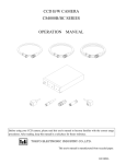
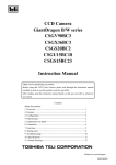
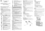
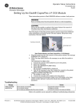
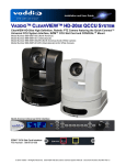
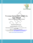
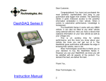
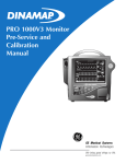
Rev 1.0
High‐
‐Resolution CCD Color Camera
MODEL CS6940CL
Specifications
Contents
1. Overview ...............................................................................1
2. Features .................................................................................1
3. Configuration ........................................................................1
4. Optional parts ........................................................................2
5. Specifications ........................................................................2
6. Serial control .........................................................................9
7. Explanation of operation .....................................................10
8. Outline Drawing..................................................................14
9. Cases for indemnity (Limited warranty) .............................15
10. Restriction for use .............................................................15
Printed on recycled paper
D4134176A
Rev 1.0
1. Overview
This CCD color camera is a high-resolution color camera that features all pixel readout mode 1/1.8 CCD.
2. Features
(1) High resolution
Bayer array high pixel density CCD (number of effective pixels 2.01 M, number of total pixels 2.11 M) is used.
(2) Square grids
The CCD pixels arrayed in square grids facilitates computation for image processing.
(3) Full-frame shutter
Since all pixels are output even by shutter operation, high resolution can be achieved, without deteriorating the
vertical resolution.
(4) Camera link interface
The interface for image output and camera control complies with the camera link standard.
By using a camera link frame grabber board for camera link, the shot image can be transferred to PC at high
speed, and various camera controls can be performed from PC.
(5) All-pixel readout mode (normal mode)
All pixel signals (in the effective area) are output in approximately 1/15 second.
(6) Partial scan mode
Partial scanning of 552 lines in the center of the screen is possible.
(7) High-speed draft readout mode
By reading 2 lines from every 8 lines, all signals in the effective area are output in approximately in 1/48 second.
(8) Random trigger shutter
By external trigger signal input, the shot image can be grabbed at an arbitrary timing.
(9) Multiple-shutter
By external trigger signal input, the shot image can be grabbed at an arbitrary timing and the accumulated shot
images can be output at an arbitrary timing.
3. Configuration
(1) Camera body·············································································· 1
(2) Accessories
Instruction Manual (Japanese)······················································· 1
Instruction Manual (English) ························································ 1
D4134176A
1
Rev 1.0
4. Optional parts
(1) Power cable
Model name: CPRC3700-**
(2) Camera Link cable
Model name: 14B26-SZLB-***-0LC
(3) Camera adapter
Model name: CA130C
(4) Camera mounting kit
Model name: CPT4000CL
*NOTE: Application software is not supplied as a standard item.
Notes on optional parts and compliance with safety standard conditions:
We assure the compliance of this camera with the safety standard when it is used in combination with the
optional parts listed above.
If you use the camera in combination with parts other than specified by our company, you are responsible
for finally confirming the compliance with the safety standard by using the entire machine/equipment.
5. Specifications
[Electrical specification]
(1) Imager
Interline CCD
・Number of total pixels
1688 (H) x 1248 (V)
・Number of effective pixels
1628 (H) x 1236 (V)
・Pixel size
4.4μm (H) x 4.4μm (V)
・Optical size
1/1.8 type
・Color filter
RGB primary color mosaic-on-tip color filter
(2) Scan method
Progressive
(3) Aspect ratio
4:3
(4) Synchronization method
Internal synchronization
(5) Standard subject illuminance
2000 lx, F11, 5000 K
(6) Minimum subject illuminance 7 lx (F1.4, GAIN MAX, all pixel readout, video level 50 %)
(7) Video output
・Data
Compliant with the camera link standard.
RGB 24bit
・Readout mode
All pixel readout
Approximately 15 fps / 1628(H) x 1236(V)
Partial scan
Approximately 30 fps / 1628(H) x 552(V)
High-speed draft readout
Approximately 48 fps / 1628(H) x 309(V)
(8) Gain
0 to +6 dB (256 levels) (initial factory setting: 0 dB)
(9) Setup
4 to 27 LSB (32 levels) (initial factory setting: 16 LSB (calculated value) )
(10) White balance
OPWB/MANU switching (initial factory setting: MANU)
(11) Gamma correction
ON/OFF switching (initial factory setting: ON)
(12) Masking correction
ON/OFF switching (initial factory setting: OFF)
D4134176A
2
Rev 1.0
(13) Power supply voltage
DC12 V ± 10% (ripple 50 mV(p-p) or less)
(14) Power consumption
Approximately 2.8 W
[Electronic shutter specification]
]
(1) Shutter speed
AE/MANU switching (initial factory setting: MANU)
・Readout mode
All pixel readout
1/15 to 1/35000 s (1250 levels)
Partial scan
1/30 to 1/35000 s (625 levels)
High-speed draft readout
1/48 to 1/35000 s (313 levels)
(2) Random trigger shutter
ON/OFF switching (initial factory setting: OFF)
・Fixed mode
The exposure time depends on the shutter speed setting.
・Pulse width mode
The exposure time depends on the pulse width.
(3) Multiple-shutter
ON/OFF switching (initial factory setting: OFF)
Exposure by TRIG input, readout by MULTI input
* Enabled when random trigger shutter is ON.
[Internal sync signal specification]
(1) Driving frequency
36.000 MHz
(2) Scanning frequency
・Readout mode
All pixel readout
Partial scan
High-speed draft readout
Horizontal
:18.750 kHz
Vertical
:15.000 Hz
Horizontal
:18.750 kHz
Vertical
:30.000 Hz
Horizontal
:15.000 kHz
Vertical
:47.293 Hz
[Input signal specification]
]
(1) TRIG
Camera link I/F and DC IN connector input
・Signal level (DC IN input)
TTL level
・Polarity
Positive/Negative polarity switching possible (initial factory setting: Negative)
・Pulse width
53.3μs or more
(2) MULTI
Camera link I/F input
・Polarity
Negative polarity
・Pulse width
53.3μs to 10 ms
D4134176A
3
Rev 1.0
[Output signal specification]
(1) WEN
DC IN connector output
・Signal level
4 V (p-p)
・Polarity
Positive polarity
・Pulse width
Approximately 53.3μs
[Dimensions]
]
(1) Lens mount
C-mount
*Depending on the lens you use, the performance of the camera may not
be brought out fully due to the deterioration in resolution and brightness
in the peripheral area, occurrence of a ghost, aberration and others.
When you check the combination between the lens and camera, be sure
to use the lens you actually use.
(2) Flange back
17.526 mm
(3) Dimensions
54 mm (W) x 43 mm (H) x 59 mm (D)
(4) Mass
Approximately 150 g
(5) Camera body grounding: insulation status
Conductive between circuit GND and camera body
[Operating ambient conditions]
]
(1) Performance assurance
Temperature
: 0 to 40°C
Humidity
: 10 to 90% (no condensation)
[Typical spectral response]
]
The lens characteristics and light source characteristics is not reflected in table.
1.0
R e la tiv e R e s p o n s e
G
0.8
B
0.6
R
0.4
0.2
0.0
400
450
500
550
600
Wave Length[nm]
650
700
[Applicable safety standards]
]
(1) EMC (Electro-Magnetic Compatibility)
EMI(Electro-Magnetic Interference)
:EN61000-6-3 / 2001
EMS(Electro-Magnetic Susceptibility)
:EN61000-6-2 / 2001
(2) FCC
:FCC Part 15 Subpart B class A
D4134176A
4
Rev 1.0
[Communication specification]
]
(1) Communication speed
9600/19200/38400 bps
(2) Data bit
None
(3) Parity
8
(4) Stop bit
1
(5) Parity bit
None
(6) Handshake
None
[Connector pin assignment]
(1) Video output/controlling connector (Camera Link Base Configuration) CAMERA LINK
・Connector model
Pin No.
1
2
3
4
5
6
7
8
9
10
11
12
13
I/O
O
O
O
O
O
I
O
I
I
I
I
-
: MDR
26-PIN connector 10226-2210VE (manufactured by 3M).
Signal Name
GND
Tx OUT0Tx OUT1Tx OUT2Tx CLK OUTTx OUT3Ser TC(RxD)+
Ser TFG(TxD)CC1(TRIG)CC2(MULTI)+
CC3CC4+
GND
Pin No.
14
15
16
17
18
19
20
21
22
23
24
25
26
I/O
O
O
O
O
O
I
O
I
I
I
I
-
Signal Name
GND
Tx OUT0+
Tx OUT1+
Tx OUT2+
Tx CLK OUT+
Tx OUT3+
Ser TC(RxD)Ser TFG(TxD)+
CC1(TRIG)+
CC2(MULTI)CC3+
CC4GND
(2)Connector for power supply and sync signal input/output DC IN
・Connector (Camera side) : HR10A-10R-12PB (Manufactured by HIROSE DENKI)
・Plug (Cable side)
: HR10A-10P-12S
Pin No.
I/O
Signal Name
1
-
GND
2
3
4
5
6
7
8
9
10
11
12
I
-
+12V
N.C.
N.C.
GND
N.C.
N.C.
GND
N.C.
WEN
TRIG
GND
O
I
-
(Manufactured by HIROSE DENKI) or equivalents
1
2
9
8
10
3
11 12 7
4
5
6
Rearview
D4134176A
5
Rev 1.0
[Switch setting]
By using the DIP switches on the back surface of the camera body, you can set serial transmission speed and
memory readout for when the power supply is turned on.
O
N
1
2
Transmission speed setting
3
4
Memory readout setting
5
6
7
8
Not used
9
10
(1) Transmission speed setting
You can set the speed of serial transmission by camera link
SW1
SW2
Transmission speed
OFF
OFF
9600 bps
ON
OFF
19200 bps
OFF
ON
38400 bps
(2) Memory readout setting
You can set the number of the setting value saving memory bank to be called when the power supply is turned on.
The memory consists of 8 banks.
SW3
SW4
SW5
Memory number
OFF
OFF
OFF
0
ON
OFF
OFF
1
OFF
ON
OFF
2
ON
ON
OFF
3
OFF
OFF
ON
4
ON
OFF
ON
5
OFF
ON
ON
6
ON
ON
ON
7
D4134176A
6
Rev 1.0
[Timing chart]
]
(1) Horizontal timing
1) All pixel readout, Partial scan
LVAL
DVAL
DATA OUT
a
b
c
d
e
a = 185CLK
b = 107CLK
c = 292CLK
d = 1628CLK
e = 1920CLK
2) High-speed draft readout
LVAL
DVAL
DATA OUT
a
b
c
d
e
a = 185CLK
b = 587CLK
c = 772CLK
d = 1628CLK
e = 2400CLK
D4134176A
7
Rev 1.0
(2) Vertical timing
1) All pixel readout
FVAL
LVAL
DVAL
DATA OUT
A
B
C
E
D
F
A = 3H
B = 10H
C = 13H
D = 1236H
E = 1H
F = 1250H
2) Partial scan
FVAL
LVAL
DVAL
DATA OUT
A
B
C
D
E
F
A = 3H
B = 41H
C = 44H
D = 552H
E = 29H
F = 625H
3) High-speed draft readout
FVAL
LVAL
DVAL
DATA OUT
B
A
C
D
F
A = 3H
B = 1H
C = 4H
D = 309H
E = 0H
F = 313H
D4134176A
8
Rev 1.0
6. Serial control
You can control following functions in camera link I/F.
(1) Memory control
・Save
・Load
・Reset
(2) Readout mode setting
All pixel readout / Partial scan/ High-speed draft readout
(3) Random trigger shutter setting
ON/OFF
* When the random shutter is active, AE setting is disabled.
・trigger polarity
Positive polarity/Negative polarity
・Random trigger mode
Pulse width mode / Fixed mode
(4) Multiple‐shutter
ON / OFF
*Enabled when random trigger shutter is ON
(5) Shutter settino
AE/MANU
* When the random shutter is active, AE setting is disabled.
・AE setting
AE Lock
AE Adjust setting
・MANU setting
1/15, 1/30, 1/48 ~ 1/35,000
(6) Gain setting
0 ~ + 6 dB (256levels)
(7) Setup setting
4 ~ 27 LSB (32levels)
(8) White balance setting
・MANU setting
OPWB / MANU
Preset setting(6data) / User manual setting (R / B Gain)setting
(9) Gamma correction
ON / OFF
(10)Masking correction
ON / OFF
D4134176A
9
Rev 1.0
7. Explanation of operation
7.1 Readout mode
Video is output from the camera link connector. The output video can be grabbed by the frame grabber board.
The frame rate and resolution of output images that this model supports are as follows:
1) All pixel readout
: Approximately 15 fps / 1628(H) x 1236(V)
2) Partial scan
: Approximately 30 fps / 1628(H) x 552(V)
3) High-speed draft readout : Approximately 48 fps / 1628(H) x 309(V)
Notes on frame dropping:
When you use a grabber board for 32-bit PCI bus, images may not be grabbed correctly because
frame dropping occurs because too much data is transferred for the transfer rate of the PCI bus.
We recommend that, in this case, you should use a grabber board for 64-bit PCI bus.
1) All pixel readout
Reads out all pixels in about 1/15 second.
1250H
FVAL
LVAL
1234
1235
1236
1
2
3
4
5
6
7
8
DVAL
DATA OUT
D4134176A
10
Rev 1.0
2) Partial scan
Skips the top and bottom of the effective area and reads out 552 lines in the center area in
approximately 1/30 second.
625H
FVAL
LVAL
892
893
894
343
344
345
346
347
348
349
DVAL
DATA OUT
Skipped lines : 342 lines
Effective lines : 552 lines
Skipped lines : 342 lines
High-speed transfer : 29 lines
+
Nomal-speed transfer : 2 lines
Effective lines : 552 lines
High-speed transfer : 29 lines
3) High-speed draft readout
By reading 2 lines out of every 8 lines, reads out the whole valid area in approximately 1/48 seconds.
313H
FVAL
LVAL
1
6
9
14
17
22
25
1225
1230
1233
DVAL
DATA OUT
Reading 2 lines out of every 8 lines in
the inside of a total of 1236 lines
Effective lines : 309
lines
D4134176A
11
Rev 1.0
7.2 Random trigger shutter
In the random trigger shutter mode, you can shoot and grab an image at an arbitrary timing by trigger
signal input from the external.
・External trigger signals can be input either from the camera link I/F CC1 or DC IN connector.
・If polarity is set to negative polarity, exposure starts at the falling edge of the trigger.
・The random trigger shutter of this camera can be operated in two types of mode: fixed mode and pulse
width mode. How to determine the exposure time differs depending on the mode.
1) Fixed mode
・The exposure time is determined by the setting value for the shutter speed.
・FVAL is output in sync with the first LVAL after the end of exposure time.
exposure time
TRIG
approx. 2.0μs
CCD
FVAL
LVAL
DVAL
DATA OUT
2) Pulse width mode
・The exposure time is determined by the pulse width (exposure time = pulse width + approximately 28μs).
・Set a pulse width of 1H (approximately 53.3μs) or more.
・FVAL is output in sync with the first LVAL after the end of exposure time.
exposure time
TRIG
approx. 2.0μs
approx. 30μs
CCD
FVAL
LVAL
DVAL
DATA OUT
D4134176A
12
Rev 1.0
7.3 Multiple-shutter mode
In the multiple-shutter mode, video is output in sync with a MULTI signal from the external after the end
of exposure time.
・Valid only when the random trigger shutter mode is ON.
・MULTI signals can be input from the camera link I/F CC2.
・If exposure is executed several times before MULTI signal input, the images are output superposed.
・The exposure time is determined by the random trigger shutter mode setting and its determination method.
・The pulse width must be set to negative polarity and 1H (approximately 53.3μs) to 10 ms.
・FVAL is output in sync with the first LVAL after the end of MULTI signal input.
TRIG
MULTI
A
B
CCD
FVAL
LVAL
DVAL
DATA OUT
A+B
D4134176A
13
Rev 1.0
8. Outline Drawing
D4134176A
14
Rev 1.0
9. Cases for indemnity (Limited warranty)
We shall be exempted from taking responsibility and held harmless for damage or losses incurred by the user in
the following cases
In the case damage or losses are caused by fire, earthquake, or other acts of God, acts by a third party,
deliberate or accidental misuse by the user, or use under extreme operating conditions.
In the case of indirect, additional, consequential damages (loss of business interests, suspension of business
activities) are incurred as result of malfunction or non-function of the equipment, we shall be exempted from
responsibility for such damages.
In the case damage or losses are caused by failure to observe the information contained in the instructions in
this instruction manual and specifications.
In the case damage or losses are caused by use contrary to the instructions in this instruction manual and
specifications.
In the case damage or losses are caused by malfunction or other problems resulting from use of equipment or
software that is not specified.
In the case damage or losses are caused by repair or modification conducted by the customer or any
unauthorized third party (such as an unauthorized service representative).
Expenses we bear on this product shall be limited to the individual price of the product.
10. Restriction for use
Should the equipment be used in the following conditions or environments, give consideration to safety
measures and inform us of such usage:
1. Use of the equipment in the conditions or environment contrary to those specified, or use outdoors.
2. Use of the equipment in applications expected to cause potential hazard to people or property, which
require special safety measures to be adopted.
This product can be used under diverse operating conditions. Determination of applicability of equipment or
devices concerned shall be determined after analysis or testing as necessary by the designer of such
equipment or devices, or personnel related to the specifications. Such designer or personnel shall assure the
performance and safety of the equipment or devices.
This product is not designed or manufactured to be used for control of equipment directly concerned with
human life (*1) or equipment relating to maintenance of public services/functions involving factors of
safety (*2). Therefore, the product shall not be used for such applications.
(*1): Equipment directly concerned with human life refers to.
· Medical equipment such as life-support systems, equipment for operating theaters.
· Exhaust control equipment for exhaust gases such as toxic fumes or smoke.
· Equipment mandatory to be installed by various laws and regulations such as the Fire Act or Building
Standard Law
· Equipment related to the above
(*2) :Equipment relating to maintenance of public services/functions involving factors of safety refers to.
· Traffic control systems for air transportation, railways, roads, or marine transportation
· Equipment for nuclear power generation
· Equipment related to the above
D4134176A
15
Rev 1.0
Head Office : 7-1, 4 chome, Asahigaoka, Hino-shi, Tokyo, 191-0065, Japan
(Overseas Sales Department)
Phone : +81-42-589-8771
Fax
: +81-42-589-8774
URL
: http://www.toshiba-teli.co.jp
Distributor
• This product must be classified for disposal according to the laws of each country and municipal laws.
• Information contained in this document is subject to change without prior notice.
D4134176A