1
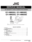
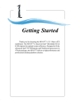
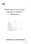
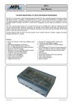
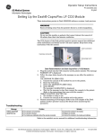
High Resolution CMOS camera
CSB1100F
Operation Manual
Thank you for purchasing our CSB1100F CMOS camera.
This operation manual includes some important information such as how to use this
equipment correctly and safely. Please read through this manual carefully. After reading, keep
this manual by the side of your equipment for your future reference.
Avoid
When performing connection, turn off power.
When connecting the power cable or connection cable, turn off the
equipment power. Otherwise, fire or electric shock may result.
Avoid
Do not expose its camera head to any intensive light (such as direct
sunlight).
Otherwise, its inner image pickup devise might get damaged.
Avoid
Avoid
Printed On Recycled Paper.
BEFORE USE – GENERAL SAFETY INSTRUCTIONS
This instruction manual contains important information for the operator (user) and/or people in the
vicinity to avoid personal injury, or property damage.
Prior to use, read this operation manual carefully to fully understand its instructions for correct use.
After reading, keep this manual near the equipment for future reference.
The meaning of each mark used in this instruction manual is given below.
[Definition of markings]
WARNING
This mark warns the user that improper use may cause death or
severe personal injury (*1) of the user or people in the vicinity.
This mark warns the user that improper use may cause personal
injuries (*2) or material damages (*3) against the user or people in
the vicinity.
*1: Severe personal injury means wounds, blindness, physical injury, burns(low temperature・
high temperature), electric shocks, fracture, addictive and others for which have aftereffects
and hospitalization or long term care are required.
*2: Personal injury means wounds, burns, electric shocks, and others for which hospitalization
or long term care are not required.
*3: Material damage means any consequential damage related to premise, possession,
domestic animals and pet.
CAUTION
[Definition of markings]
This mark indicates what the user SHOULD NOT DO. The details are given adjacent
the mark.
This mark indicates what the user MUST DO. The detail are given adjacent the mark.
●Handling Precautions
WARNING
Unplug
Do not get wet
Never pull
apart
Immediately cease of the equipment in the event of abnormality or
malfunction.
If abnormal conditions are present, such as smoke, a burning smell, ingress
of water or foreign matter, or if the equipment is dropped or malfunctions, fire
or electric shock may result.
If such abnormalities occur, disconnect the power plug from the outlet and
contact your sales representative.
Do not use the equipment in locations subject to water splashes.
Otherwise, fire or electric shock may result.
Do not disassemble, repair, or modify the equipment.
Otherwise, fire or electric shock may result.
For internal repair, inspection, or cleaning, contact your sales representative.
Avoid
Do not place anything on the equipment.
If metallic objects, liquid, or other foreign matter enters the equipment, fire or
electric shock may result.
Avoid
Do not install the equipment in an unstable or inclined location or locations
subject to vibration or impact.
Otherwise, the equipment may topple over and cause personal injury.
Do not touch
During an electrical storm, do not touch the power cord or connection
cable.
Otherwise, an electric shock may result.
Instruction
Avoid
Use the specified power supply.
Use of an unspecified power supply may result in fire or electric shock.
Do not be handled roughly, damaged, fabricated, bent forcefully, pulled,
twisted, bundled, places under heavy objects or heated the power cord,
connection cable.
Otherwise, fire or electric shock may result.
CAUTION
Instruction
Avoid
Avoid
Avoid
Observe the following when installing the equipment.
• Do not cover the equipment with a cloth, etc.
• Do not place the equipment in a narrow location where heat is likely to
accumulate. Otherwise, heat will accumulate inside the equipment, possibly
resulting in a fire.
Do not place the equipment in locations subject to high moisture, oil fumes,
stream, or dust.
Otherwise, fire or electric shock may result.
Do not install the equipment in locations exposed to direct sunlight or
humidity.
Otherwise, the internal temperature of the equipment will rise, which may
cause a fire.
Use only specified DC power cables and connection cables.
Otherwise, fire or electric shock may result.
Instruction
Avoid short-circuiting signal output.
Otherwise, a malfunction may occur.
Avoid giving a strong shock against the camera body.
If your camera is used in a system where its camera connector is subjected
to strong repetitive shocks, its camera connector is possible to break down.
If you intend to use your camera in such a situation, if possible, bundle and
fix a camera cable in the place near the camera, and do not transmit a shock
to the camera connector.
Contact your sales representative to request periodic inspection and
cleaning (every approx. five years).
Accumulation of dust inside the equipment may result in fire or electric
shock.
For inspection and cleaning costs, contact your sales representative.
CASE FOR INDEMNITY(LIMITED WARRANTY)
We shall be exempted from taking responsibility and held harmless for damage or losses incurred
by the user in the following cases.
In the case damage or losses are caused by fire, earthquake, or other acts of God, acts by a
third party, deliberate or accidental misuse by the user, or use under extreme operating
conditions.
In the case of indirect, additional, consequential damages (loss of business interests,
suspension of business activities) are incurred as result of malfunction or non-function of the
equipment, we shall be exempted from responsibility for such damages.
In the case damage or losses are caused by failure to observe the information contained in the
instructions in this instruction manual and specifications.
In the case damage or losses are caused by use contrary to the instructions in this instruction
manual and specifications.
In the case damage or losses are caused by malfunction or other problems resulting from use
of equipment or software that is not specified.
In the case damage or losses are caused by repair or modification conducted by the customer
or any unauthorized third party(such as an unauthorized service representative).
Expenses we bear on this product shall be limited to the individual price of the product.
About the item which does not have a publication in the specifications and manual of this
product, it considers as the outside for a guarantee.
RESTRICTION FOR USE
Should the equipment be used in the following conditions or environments, give consideration
to safety measures and inform us of such usage:
1. Use of the equipment in the conditions or environment contrary to those specified, or use
outdoors.
2. Use of the equipment in applications expected to cause potential hazard to people or
property, which require special safety measures to be adopted.
This product can be used under diverse operating conditions. Determination of applicability of
equipment or devices concerned shall be determined after analysis or testing as necessary by
the designer of such equipment or devices, or personal related to the specifications. Such
designer or personal shall assure the performance and safety of the equipment or devices.
This product is not designed or manufactured to be used for control of equipment directly
concerned with human life(*1) or equipment relating to maintenance of public
services/functions involving factors of safety(*2). Therefore, the product shall not be used for
such applications.
(*1): Equipment directly concerned with human life refers to:
• Medical equipment such as life-support systems, equipment for operating theaters.
• Exhaust control equipment for exhaust gases such as toxic fumes or smoke.
• Equipment mandatory to be installed by various laws and regulations such as the Fire Act
or Building Standard Law.
• Equipment related to the above.
(*2): Equipment relating to maintenance of public services/functions involving factors of safety
refer to:
• Traffic control systems for air transportation, railways, roads, or marine transportation.
• Equipment for nuclear power generation.
• Equipment related to the above.
Usage Precautions
Handle carefully
Do not drop the equipment or allow it to be subject to strong impact or vibration, as such action
may cause malfunctions. Further, do not damage the connection cable, since this may cause
wire breakage.
Environmental operating conditions
Do not use the product in locations where the ambient temperature or humidity exceeds
specifications. Otherwise, image quality may be degraded or internal components may be
adversely affected. In particular, do not use the product in areas exposed to direct sunlight.
More over, during shooting under high temperatures, vertical stripes or white spots (noise) may
be produced, depending on the subject or camera conditions (such as increased gain).
However, such phenomena are not malfunctions.
Do not shoot under intense light
Avoid intense light such as spotlights on part of the screen because it may cause blooming or
smears. If intense light falls on the screen, vertical stripes may appear on the screen, but this is
not a malfunction.
Occurrence of moiré
If you shoot thin stripe patterns, moiré patterns (interference fringes) may appear. This is not
malfunction.
Occurrence of noise on the screen
If an intense magnetic or electromagnetic field is generated near the camera or connection
cable, noise may be generated on the screen. If this occurs, move the camera or the cable.
Handling of the protective cap
If the camera is not in use, attach the lens cap to the camera to protect the image pickup
surface.
If the equipment is not to be used for a long duration
Turn off power to the camera for safety.
Maintenance
Turn off power to the equipment and wipe it with a dry cloth.
If it becomes severely contaminated, gently wipe the affected areas with a soft cloth dampened
with diluted neutral detergent. Never use alcohol, benzene, thinner, or other chemicals because
such chemicals may damage or discolor the paint and indications.
If the image pickup surface becomes dusty, contaminated, or scratched, consult your sales
representative.
Disposal
When disposing of the camera, it may be necessary to disassemble it into separate parts, in
accordance with the laws and regulations of your country and/or municipality concerning
environmental contamination.
7. Connection
CMOS sensor characteristics
• Defective pixels
A CMOS image sensor is composed of photo sensor pixels in a square grid array. Due to the
characteristics of CMOS image sensors, over- or under-driving of the pixels results in temporary
white or black areas (as if these are noises) appearing on the screen. This phenomenon, which is
not a defect is exacerbated under higher temperatures and long exposure times.
• Image shading
Under global shutter operation, the brightness of the upper part of the screen may differ from the
lower part. And, the brightness of the left part on the screen may differ from the right part.
However, this does not mean the CMOS image sensor is defective.
This phenomenon occurs under short exposure times and high illumination.
To counteract this phenomenon, reduce the illumination by setting a longer exposure time, or
adjust the lens aperture.
It may be blurred by this phenomenon when fast-moving subject captured.
1. Product Description
Model CSB1100F is a high-resolution B/W CMOS camera achieving high-speed image processing
by a random access.
2. Features
(1) Ultra-high resolution
The CSB1100F features a high-pixel CMOS sensor (Total pixel count: 1.30 Mega pixels),
enabling high-density images (i.e., significantly reduced moiré and beat) to be obtained.
(2) Global shutter mode
This model features a Global shutter mode, which means that clear images of a fast-moving
subject with little blurring are obtained.
(3) Random trigger shutter mode
This feature starts light-exposure in synchronization with external trigger signal, and enables
image capture at any given timing.
(4) WOI(Window Of Interest)
WOI is a feature enabling high-speed image processing.
By designating horizontal and vertical addresses, user-defined areas only are read out.
(5) High-dynamic range
This model features a high-dynamic range with multi slope integration mode, both high-and
low-intensity subjects can be captured at the same time despite the high difference in contrast.
3. Configuration
(1) Camera body -----------------------(2) Operation Manual -------------------
1
1
4. Optional parts
(1) IEEE1394 cable (Recommended harness HSB-HCC-***)
(2) Camera mounting kit (Model name: CPT1100CL)
(3) TFL lens mount adapter (Model name: TCAR)
*NOTE: Application software is not supplied as a standard item.
5. Designation and Operation of each Part
(1) IEEE1394 Connector Digital data IN/OUT terminal
The VIDEO signal and the command are sent and received.
This connects to IEEE1394 interface board.
.
(2) Trigger connector
It is an input terminal of the trigger pulse.
(1) IEEE1394
Connector (Camera side): 67430-001 (Manufactured by MOLEX)
Plug (Cable side): HSB-HCC-*** (Manufactured by DDK)
PIN No.
1
2
3
4
5
6
Signal name
POWER
POWER(GND)
TPBTPB+
TPATPA+
(2) DATA IN/OUT
Connector (Camera side): 10226-2210VE (Manufactured by 3M)
Connector (Cable side): 10126-6000 (Manufactured by 3M)
PIN No.
1
2
3
4
Signal name
TRIG
TRIG(GND)
N.C.
S.G.
I/O
I
I
I
Notes
Be sure use in open
8. Function
(1) Electronic shutter
The shutter-speed of CSB1100F is also manually adjustable. By manipulating the internal register
setting value of CSB1100F, you can change the shutter-speed by user-defines setting value of 62.5
micro sec step.
*The longer a user sets the exposure time, the more defective pixels on the image is outstanding.
When you attach importance to image quality, it is recommendable to set the shutter speed at
30 msec or less.
(2) Random trigger shutter
Under the RTS mode, the camera can capture image at any user-defined timing with external
trigger signal. Under FIX mode, shutter speed can be set with the internal resister setting value.
Under pulse mode, shutter speed can be set with the trigger pulse width.
You can change the polarity of trigger pulse with the internal resister setting value.
(3) Multi slope function
By changing a slope position with internal resister setting value, you can set the sensitivity
matching to the subject luminance.
Refer to the interface specifications for the detail of the setting method separately.
(4) WOI (Window Of Interest)
Only user-defined area can be captured by designating of the horizontal and the vertical address.
Up to 16 areas can be set in 1 screen.
This function can increase a frame rate because the area other than designated is not captured.
The minimum area size is 50 dot(H) x 50 dot(V).
Horizontal address can set up only even number.
• The placement is available up to 16 windows in all active pixel area.
1
6. Mounting the camera
There are various methods of fixing the camera. Choose from among the following options.
(1) Option 1: Using a camera tripod fixing kit.
Use an optional tripod fixing kit (1/4-20UNC) to fix the camera onto the tripod. Use attached
screws to affix tripod-mounting hardware to your camera. (See the figure below)
(2) Option 2: Using the mounting holes
If not using the tripod fixing kit, make sure that the M3 screws do not penetrate more than 6 mm
into the camera body.
I/O
I
I
I/O
I/O
I/O
I/O
2
5
9
4
3
8
11
12
15
7
6
16
10
14
13
• The setting of readout address is available up to 8 types.
1 2
34
5
67
8
Ver.1.02
10. Timing Chart
Practical operation example
In the case of only one readout area
A readout area can be designated by the start
address (X1, Y1) and the end address (X2, Y2).
The camera can read out the user-defined area
through this function.
The each address is designated by the start
address and lengths (pixel numbers) of “X” and
“Y” directions.
(X1,Y1)
(1)
(2)
(3)
(4)
(5)
(6)
(7)
(X2,Y2)
(X1,Y1)
A-block
In the case of more than two readout areas
The area designated by the start address (X1, Y1)
and the end address (X2, Y2) is read out first
(A-block in the left figure).
After reading out of A-block, the next area
designated by (X3, Y3) and (X4, Y4) is read out
(B-block in the left figure)
(1)
(2)
(3)
(4)
(5)
(6)
(7)
(X2,Y2)
(X3,Y3)
B-block
(8)
(9)
(10)
(11)
(12)
(13)
(14)
(5) Scalable (Pulse width control, Format 7 mode 1)
11. External View
(1) Normal shutter mode (Format 7 mode 0)
(2) Random Trigger Shutter mode (Fix mode, Format 7 mode 0)
(X4,Y4)
(X1,Y1)
A-block
(1)
(2)
(3)
(4)
(5)
(6)
(7)
(9)
(11)
(13)
(15)
(X3,Y3)
(X2,Y2)
In the case of more than two readout areas and
including the same readout lines with each other
The designated areas are read out in order of
address from the start (X1, Y1) to the end (X4,
Y4).
B-block
(8)
(10)
(12)
(14)
(16)
(17)
(18)
(19)
(20)
(6) WOI mode (Fix mode, Format X)
(X4,Y4)
(X1,Y1)
A-block
(X3,Y3)
(1)
(2)
(4)
(6)
B-block
(3)
(5)
(7)
(8)
(X2,Y2)
(X4,Y4)
(X5,Y5)
(X7,Y7)
C-block
D-block
In the case of four readout areas
The designated areas are read out in order of
address from start (X1, Y1) to the end (X8, Y8).
(9)
(11)
(13)
(15)
(10)
(12)
(14)
(16)
(X8,Y8)
(X6,Y6)
Shutter speed depends on the internal resister setting value.
After trigger IN, next trigger signal is not acceptable until the readout is completed.
9. Specification
[Electronic Specification]
]
(1) Image sensor
CMOS image sensor
• Total pixel
1280(H) x 1024(V)
• Active pixel
1240(H) x 1024(V)
• Pixel size
6.7(H) x 6.7(V) micro m
• Image area
8.308mm(H) x 6.854mm(V)
• Driving frequency
39.3216 MHz
(2) Scanning line
1024 lines
(3) Scanning system
Progressive
(4) Frame rate
16 fps(Exposure time: 62.5 micro sec)
(5) Sync system
Internal
(6) Aspect ratio
5:4
(7) Subject illumination
2600lx,F5.6(3100K)(Exposure time: Approx 16 msec)
(8) Video output time
Approx. 62.2 msec
(9) Interface
Conforms to IEEE Std. 1394a-2000
Transfer speed
400Mbps
(10) Video mode
Format7/Special format (in WOI) Mono 8bit
(11) Protocol
Conforms to 1394-based Digital Camera Specification ver.1.3
(12) Input signal
TRIG (Shutter Trigger) 3.3V CMOS level
Grabbing timing
Falling edge detection
Pulse width
Minimum : 5 micro sec
Max : no limit
(13) Electronic shutter
Shutter speed (preset inside the camera) selection via communication
command 1 through 4000 (approx. 62.5 micro sec through 1 sec)
(14) Shutter mode
Global shutter
(15) Random Trigger
RTS operation is available by external trigger input. Shutter speed
Shutter
preset or shutter speed control by pulse width is available.
Mode 0
Shutter speed preset mode (preset inside camera)
Mode 1
Shutter speed can be controlled via shutter trigger pulse width.
The camera starts light-exposure at the falling edge timing and ends it at
the rising edge timing.
(16) Power supply
DC+8V through DC+30V (IEEE1394 cable power supply)
(17) Power condition
Approx. 1.5W (at +30V)
Approx. 1.4W (at +12V)
Approx. 1.4W (at +8V)
[Mechanical Specification]
]
(1) External dimension
44(W)×29(H)×52(D) mm(Without projection)
(2) Weight
Approx. 120 g
(3) Lens mount
C-mount
(4) Flange back
17.526 mm
(5) Chassis grounding
Between Connector shell and FG
Continuity provided
/insulation
Between FG and SG
Continuity not provided
[Use environmental conditions]
]
(1) Ambient condition
Temperature:
Performance guaranteed From 0 through 40 degrees Celsius
Operation guaranteed
From –5 through 45 degrees Celsius
Preservation
From –20 through 60 degrees Celsius
Humidity:
Performance guaranteed From 20 through 80 % (No condensing)
Operation guaranteed
From 20 through 80 % (No condensing)
Preservation
From 20 through 95 % (No condensing)
(3) Random Trigger Shutter (Pulse width control, Format 7 mode 0)
(7) WOI mode (Pulse width control, Format X)
Shutter speed depends on the trigger pulse width.
After trigger IN, next trigger signal is acceptable until the readout is completed.
(4) Scalable (Fix mode, Format 7 mode 1)
Following information is only for EU-member states:
The use of the symbol indicates that this product may not be treated as household
waste. By ensuring this product is disposed of correctly, you will help prevent
potential negative consequences for the environment and human health, which
could otherwise be caused by inappropriate waste handling of this product.
For more detailed information about the take-back and recycling of this product,
please contact your supplier where you purchased the product.
”This symbol is applicable for EU member states only”
Head Office: 7-1, 4 chome, Asahigaoka, Hino-shi, Tokyo, 191-0065, Japan
(Overseas Sales Department)
Phone: +81-42-589-8771 Fax: +81-42-589-8774
URL: http://www.toshiba-teli.co.jp
[Interface specification]
]
Please contact our sales person about interface specification.
Ver.1.02