1
FIRST EDITION
SEPT. 2009
MY8-13AK-000
COPYRIGHT © CANON ELECTRONICS INC. 2009
CANON DR-2020U FIRST EDITION
COPYRIGHT © CANON ELECTRONICS INC. 2009
Use of this manual should be
strictly supervised to avoid
disclosure
information.
of
confidential
PREFACE
This Service Manual describes necessary basic information for field service and maintenance for
maintaining the product quality and functions of this machine.
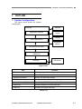
Contents
Chapter 1: General description
Features, specifications, name of parts, operation method
Chapter 2: Functions and operation
Description of operation of machine system and electrical system by function
Chapter 3: Disassembly and reassembly
Disassembly method, reassembly method
Chapter 4: Installation and maintenance
Installation method, maintenance method
Chapter 5: Troubleshooting
Error display and troubleshooting
Appendix: General electrical block diagram and parts catalog, etc.
Information in this manual is subject to change. Notification of such changes will be given in Service
Information Bulletins.
Thoroughly read the information contained in this Service Manual and the Service Information Bulletins
to gain a correct and deeper understanding of the machine. This is one way of fostering response for
ensuring prolonged quality and function, and for investigating the cause of trouble during troubleshooting.
Quality Assurance Center
Canon Electronics Inc.
COPYRIGHT © CANON ELECTRONICS INC. 2009
CANON DR-2020U FIRST EDITION
CONTENTS
CHAPTER 1
GENERAL DESCRIPTION
I.
2. Lower CCD PCB ...............................2-19
3. ADF Relay PCB ................................2-20
OUTLINE ................................................. 1-1
CHAPTER 3
DISASSEMBLY &
REASSEMBLY
1. Features.............................................. 1-1
2. Specifications ...................................... 1-2
3. Precautions ......................................... 1-5
II.
III.
NAME OF PARTS.................................... 1-6
I.
ADF UNIT ................................................3-1
1. Front Side ........................................... 1-6
1. ADF Unit (Entire).................................3-1
2. Operation Panel .................................. 1-7
2. Pickup Tray Unit..................................3-1
3. Rear Side ............................................ 1-7
3. ADF Front Cover.................................3-2
USER OPERATION................................. 1-8
4. ADF Rear Cover .................................3-3
1. Document Setting ............................... 1-8
5. Business Card Tray Unit .....................3-4
2. CaptureOnTouch................................. 1-9
6. Business Card Roller ..........................3-4
3. Paper Jam Handling ......................... 1-11
7. Feed Cover .........................................3-5
8. Hinge (Right).......................................3-6
9. Hinge (Left) .........................................3-6
CHAPTER 2
FUNCTIONS & OPERATION
I.
III.
11. ADF Cable .........................................3-7
OUTLINE ................................................. 2-1
12. ADF Relay PCB .................................3-8
1. System Configuration ......................... 2-1
13. Feed and Reading Unit......................3-8
2. Machine Configuration........................ 2-2
14. ADF Bottom Cover ............................3-9
3. Outline of Electric Circuit .................... 2-3
II.
10. Feed Motor ........................................3-7
II.
FLATBED UNIT......................................3-10
READING SYSTEM................................. 2-4
1. Top Cover..........................................3-10
1. Outline................................................. 2-4
2. Front Lower Cover ............................ 3-11
2. Flatbed ................................................ 2-5
3. Operation Panel Unit......................... 3-11
3. Feeder................................................. 2-8
4. Reading Unit .....................................3-12
FEED SYSTEM ....................................... 2-9
5. Main PCB ..........................................3-13
1. Outline................................................. 2-9
2. Pickup Operation .............................. 2-10
CHAPTER 4
INSTALLATION &
MAINTENANCE
3. Feed Operation ................................. 2-11
4. Sequence of Operation..................... 2-12
5. Business Card Feeding .................... 2-13
IV.
CONTROL SYSTEM ............................. 2-14
I.
1. Checking the Accessories...................4-1
1. Control Block Diagram...................... 2-14
2. Removing the Packing Materials ........4-2
2. Image Processing ............................. 2-15
V.
ELECTRICAL PARTS LAYOUT............. 2-17
VI.
PARTS LAYOUT ON PCB ..................... 2-18
1. Main PCB.......................................... 2-18
COPYRIGHT © CANON ELECTRONICS INC. 2009
INSTALLATION........................................4-1
3. Installing the Software.........................4-3
4. Connection to a Computer ..................4-4
5. Turning the Scanner ON .....................4-4
II.
PARTS REPLACEMENT .........................4-5
CANON DR-2020U FIRST EDITION
1. Periodically Replaced Parts ............... 4-5
2. Consumable Parts.............................. 4-5
III.
MAINTENANCE ...................................... 4-6
1. User Maintenance .............................. 4-6
2. Service Maintenance.......................... 4-7
CHAPTER 5
TROUBLESHOOTING
I.
ERROR DISPLAY ................................... 5-1
1. Operation Panel ................................. 5-1
2. Computer............................................ 5-3
II.
LIST OF ERRORS .................................. 5-4
1. Operation Errors................................. 5-4
2. Images Errors ..................................... 5-5
III.
OPERATION TROUBLESHOOTING ...... 5-6
1. No Power............................................ 5-6
2. Not Recognized by Computer ............ 5-7
3. Scanning Does Not Start .................... 5-8
4. Slow Scanning Speed ........................ 5-9
5. Motor Does Not Work....................... 5-10
6. Document is Not Fed.........................5-11
7. Document is Not Properly Fed
(Jam/Double Feed/Skew) ................5-11
IV.
IMAGE TROUBLESHOOTING ............. 5-12
1. Completely Black/Completely White 5-13
2. Too Dark/Too Light ........................... 5-14
3. Black Borders Around Image............ 5-14
4. Image Skews .................................... 5-15
5. Moire on Image ................................ 5-15
6. Spots and Streaks on Image ............ 5-16
7. Outer Areas of Image Disappear...... 5-16
APPENDIX
I.
ELECTRICAL BLOCK DIAGRAM ........... A-1
II.
PARTS CATALOG ................................... A-2
1. ADF Unit ............................................. A-2
2. Flatbed Unit ........................................ A-4
COPYRIGHT © CANON ELECTRONICS INC. 2009
CANON DR-2020U FIRST EDITION
CHAPTER 1
GENERAL DESCRIPTION
I.
OUTLINE..................................................1-1
II.
NAME OF PARTS ....................................1-6
COPYRIGHT © CANON ELECTRONICS INC. 2009
III.
USER OPERATION .................................1-8
CANON DR-2020U FIRST EDITION
CHAPTER 1 GENERAL DESCRIPTION
I. OUTLINE
1. Features
1) Upper model for DR-1210C
1-path duplex scanning is available
2) Three way scanning
Feeder (1-path duplex scanning)
Flatbed
Business card
3) Reading speed (feeder, A4)
Black and White/Grayscale, 200/300 dpi: Simplex 20 ppm, Duplex 40 ipm
Color, 200 dpi: 20 ppm, 20 ipm, 300 dpi: 13 ppm, 12 ipm
4) Easy scan
Improved Job function
5) Service ability is improved
Service parts are increased (adding the main PCB, ADF unit, flatbed unit etc.)
“Windows” is a trademark of Microsoft Corporation in the U.S. and other countries.
Other company names and product names mentioned in this document are registered trademarks or
trademarks of the respective companies.
COPYRIGHT © CANON ELECTRONICS INC. 2009
CANON DR-2020U FIRST EDITION
1-1
CHAPTER 1 GENERAL DESCRIPTION
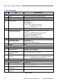
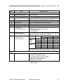
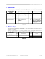
2. Specifications
No.
Item
Appearance / Installation
1
Type
2
Dimensions
3
4
Weight
Power rating
5
6
External interface
Expected product life
(In-house information)
7
8
Installation
Consumable parts
(commercial goods)
9
Option
Feeder (ADF)
10
Document feed path
11
Document size
12
13
Document weight
(thickness)
Document storage
(pickup)
14
Double feed detection
Business card
15
Document feed path
16
Document size
17
18
Document weight
(thickness)
Document storage
(pickup)
Specifications
Desktop type A4 flatbed scanner with ADF
Tray closed: 440 (W) × 400 (D) × 180 (H) mm
7.8 kg (Main body only, excepting AC adapter)
1) Main body
24 VDC, 1.2 A
2) AC adapter
Input: 100 V-240 VAC, 50/60 Hz,
1.2 A (100 V)-0.7 A (240 V)
Output: 24 VDC, 2.2 A
USB2.0 (Hi-Speed)
One of the following items, whichever comes first.
1) 5 years
2) Feeder: 150,000 sheets (A4 copy paper)
* There are parts needed to replace.
3) Flatbed: 50,000 sheets
4) Business card slot: 15,000 sheets
By user
1) Roller unit
2) Separation pad
* Expected life 50,000 sheets
None
U-turn path
1) Width: 139.7 to 216 mm
2) Length: 100 to 355.6 mm
50 to 128 g/m2 (0.06 to 0.15 mm)
1) A4 or less: 50 sheets max. and 5 mm height max.
2) A4 over: Feeding function is no guarantee, and recommended one sheet at a time.
Length detection only
Straight path
1) Width: 49 to 55 mm
2) Length: 85 to 91 mm
128 to 300 g/m2 (0.15 to 0.30 mm)
15 sheets max.
Table 1-101a
1-2
COPYRIGHT © CANON ELECTRONICS INC. 2009
CANON DR-2020U FIRST EDITION
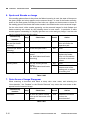
CHAPTER 1 GENERAL DESCRIPTION
No.
Item
Flatbed
19
Maximum reading size
Document reading
20
Number of reading units
21
22
23
24
25
Reading type/elements
Light source
Background color
Image data memory size
Output mode
(at CapturePerfect3.0)
26
Output resolution
(at CapturePerfect3.0)
27
Reading speed
(at A4 size, and
CapturePerfect3.0)
Others
28
Operation panel
Specifications
216 × 297 mm
1) One in the ADF, it is called as upper reading unit.
2) One in the FB, it is called as lower reading unit.
CCD-ROS (Reduction Optical System)
CCFL (Cold Cathode Fluorescent Lamp)
Black
64 MB
1) Binary (Black and White/Error diffusion/ATE/ATE-II)
* ATE=Advanced Text Enhancement
2) Grayscale (8 bit)
3) Color (24 bit)
100 × 100 dpi, 150 × 150 dpi, 200 × 200 dpi, 240 × 240 dpi,
300 × 300 dpi, 400 × 400 dpi, 600 × 600 dpi
ADF
FB
ResoluMode
tion
Simplex
Duplex
Sheet
B&W/
200 dpi
20 ppm
40 ipm
3.6 sec
Gray300 dpi
20 ppm
40 ipm
3.6 sec
scale
600 dpi
10 ppm
12 ipm
4.8 sec
Color
200 dpi
20 ppm
20 ipm
3.6 sec
300 dpi
13 ppm
12 ipm
4.8 sec
600 dpi
6 ppm
5 ipm
8.7 sec
* The numbers above may differ depending on the
computer, the function settings and other conditions.
1)
2)
3)
4)
5)
6)
POWER button
START button, STOP button
Job buttons (COPY, FILE, E-MAIL)
User Job buttons (A, B, C, D, E)
Job scroll keys (Up, Down)
Display panel (LCD)
Table 1-101b
COPYRIGHT © CANON ELECTRONICS INC. 2009
CANON DR-2020U FIRST EDITION
1-3
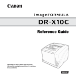
CHAPTER 1 GENERAL DESCRIPTION
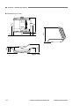
60
247
440
150
140
180
50
415
400
Dimensions (unit: mm)
Figure 1-101
1-4
COPYRIGHT © CANON ELECTRONICS INC. 2009
CANON DR-2020U FIRST EDITION
CHAPTER 1 GENERAL DESCRIPTION
3. Precautions
4)
This section describes items that require
particular care, for example, regarding human
safety.
These precautions must be observed.
The user should be explained the items that
relate to user safety and instructed to take
appropriate actions.
1) Power OFF in emergency
If such abnormal conditions as extraordinary noise, smoke, heat and odor occur,
immediately unplug the power cord.
Be careful not to get clothing (ties, long
hair, etc.) caught in this machine as it may
cause injury. Should this occur, immediately unplug the power cord.
Do not insert fingers in the feed section
while moving the rollers.
Electromagnetic wave interference
This machine complies with some standards regarding electromagnetic wave
interference, such as VCCI and FCC.
However, the user may have to take
countermeasures if the machine causes
electromagnetic wave interference.
5) “User Manual”
Read each “User Manual” thoroughly prior
to use of this machine.
6) Disposal
Follow local regulations when disposing of
the product and parts. This product is
subject to the WEEE Directive in Europe.
The lamps (CCFL) for the reading units
inside this product contain Mercury and
must be recycled or disposed according to
local, state or federal laws.
2) Power OFF on disassembling
When disassembling and assembling are
performed, unplug the power cord.
3) Prohibition of modify
This machine must not arbitrarily be
modified or remade. If it is, use may be
forcibly suspended.
To change the specifications or disassemble and reassemble this machine,
follow the instructions described in this
manual and the service information.
COPYRIGHT © CANON ELECTRONICS INC. 2009
CANON DR-2020U FIRST EDITION
1-5
CHAPTER 1 GENERAL DESCRIPTION
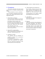
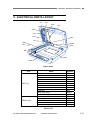
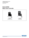
II. NAME OF PARTS
1. Front Side
1
2
3
4
7
8
9
10
11
6
5
Figure 1-201
□1 Feeder Cover
□2 Document Guides *See Note
□3 Document Feed Tray *See Note
□4 Document Eject Tray
□5 Eject Tray Extension
□6 Operation Panel
□7 Business Card Feeder
□8 Pressure Board
□9 Scanning Glass (Feeder) *See Note
10 Lock Switch
□
11 Scanning Glass (Flatbed) *See Note
□
Note:In this manual, “Document Feed Tray” and “Document Guides” together may be mentioned as “Document Pickup Tray”. And “Scanning Glass” may be mentioned as “Reading
Glass”.
1-6
COPYRIGHT © CANON ELECTRONICS INC. 2009
CANON DR-2020U FIRST EDITION
CHAPTER 1 GENERAL DESCRIPTION
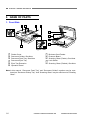
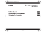
2. Operation Panel
1
2 3
4
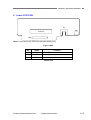
3. Rear Side
5 6 7
8
Figure 1-202
□1
□2
□3
□4
□5
□6
□7
□8
Job Buttons (COPY, FILE, E-MAIL)
Display Panel
User Defined Job Buttons (A, B, C,
D, E)
Power Indicator
Scroll Keys (Up, Down)
START Button
STOP Button
POWER Button
COPYRIGHT © CANON ELECTRONICS INC. 2009
1
2
3
Figure 1-203
□1
□2
□3
CANON DR-2020U FIRST EDITION
USB Connector
ADF Connector
Power Connector
1-7
CHAPTER 1 GENERAL DESCRIPTION
III. USER OPERATION
For details, refer to the “User Manual” of
this machine.
For installation and maintenance, refer to
“CHAPTER 4 INSTALLATION &
MAINTENANCE”.
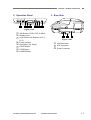
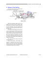
1. Document Setting
There are three feeding methods (feeder,
flatbed, business card feeder) for scanning
documents with this scanner. The types of
documents that can be scanned with each
method. Each document method is different
with its feeding method.
1) Feeder
Fan the pages of the document to be
scanned, and load the document into the
feeder with the scanning side facing up.
And then, adjust the document guides to
the edges of the document.
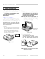
2) Flatbed
Place the document on the flatbed with the
scanning side facing down, and align the
upper left corner of the document with the
positioning guide on the flatbed.
Note:Open and close the feeder gently. Excessive force may result in damage to
the feeder or breaking the scanning
glass and personal injury.
Scanning Side
Facing Down
Figure 1-302
3) Business card feeder
Open the business card feeder.
And then, place the cards into the business card feeder with the scanning side
facing up.
Figure 1-301
Figure 1-303
Note:Close the business card feeder when
scanning has finished.
1-8
COPYRIGHT © CANON ELECTRONICS INC. 2009
CANON DR-2020U FIRST EDITION
CHAPTER 1 GENERAL DESCRIPTION
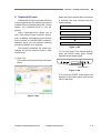
2. CaptureOnTouch
A [CaptureOnTouch] and [CapturePerfect
3.0] are supplied with the scanner, and can be
installed from the supplied Setup disc. On this
section, the CaptureOnTouch is only described.
Using CaptureOnTouch allows you to
scan using easy-to-follow onscreen instructions. In addition, by assigning scan functions
to the buttons on the DR-2020U scanner's
operation panel, you can perform scanning
procedures without your computer.
The following describes the output procedures for the two screens found in CaptureOnTouch.
1) Scan First
The screen of the [Scan First] tub is shown
below.
Select an output method after a document
is scanned, and then configure the necessary settings.
Scan document
Select output method
Configure output settings
Output scanned images
Figure 1-305
To use the Scan First default settings,
press the START button when “Ready”
appears on the display panel.
START Button
Figure 1-306
If you press the START button while a job
appears on the display panel, scanning for
that job will begin.
Figure 1-304
COPYRIGHT © CANON ELECTRONICS INC. 2009
CANON DR-2020U FIRST EDITION
1-9
CHAPTER 1 GENERAL DESCRIPTION
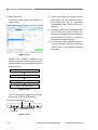
2) Select Scan Job
The screen of the [Select Scan Job] tub is
shown below.
● Three preset jobs are assigned to the
job buttons, and the respective scanning procedures will be processed
automatically when these buttons are
pressed.
● Registered jobs can be assigned to the
user defined job buttons. When you
press a user defined job button and then
press the START button, the scan job
assigned to the button begins.
● You can also select registered jobs using the scroll keys. When you press the
START button, the selected scanning
job begins.
Figure 1-307
Register the scanning conditions and
output methods as jobs, and then select a
job that matches your intended purpose to
begin scanning.
Register jobs
Select job
Scan document
Output scanned images
Figure 1-308
You can also select registered jobs using
the buttons on the operation panel.
User Defined Job Buttons
Scroll Keys
Job Buttons
Figure 1-309
1-10
COPYRIGHT © CANON ELECTRONICS INC. 2009
CANON DR-2020U FIRST EDITION
CHAPTER 1 GENERAL DESCRIPTION
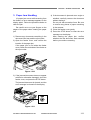
3. Paper Jam Handling
If a paper jam occurs while scanning from
the feeder, an error message appears on the
display panel. Follow the procedure below to
clear the jam.
Be careful not to cut your fingers on the
edges of the paper when clearing the paper
jam.
1) Remove any documents remaining in the
document feed tray and the eject outlet.
2) Open the feeder cover, and confirm the
location of the paper jam.
If the paper jam is not inside the feeder
cover, check the underside of the feeder or
the eject outlet.
4) If the document is jammed at an angle or
wrinkled, carefully remove the document
without tearing it.
Do not pull with excessive force. Be sure
to remove any pieces of paper remaining
in the scanner.
5) Close the feeder cover gently.
6) Press the STOP button to clear the error
message on the display.
After clearing the paper jam, confirm
whether the last document was scanned
before you continue scanning.
Figure 1-310
3) If the jammed document does not appear
wrinkled or otherwise damaged, close the
feeder cover, and press the STOP button.
The jammed document is ejected, and the
error message is cleared on the display.
Figure 1-311
COPYRIGHT © CANON ELECTRONICS INC. 2009
CANON DR-2020U FIRST EDITION
1-11
CHAPTER 2
FUNCTIONS & OPERATION
I.
OUTLINE..................................................2-1
IV.
CONTROL SYSTEM ..............................2-14
II.
READING SYSTEM .................................2-4
V.
ELECTRICAL PARTS LAYOUT .............2-17
III.
FEED SYSTEM ........................................2-9
VI.
PARTS LAYOUT ON PCB......................2-18
COPYRIGHT © CANON ELECTRONICS INC. 2009
CANON DR-2020U FIRST EDITION
CHAPTER 2 FUNCTION & OPERATION
I. OUTLINE
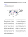
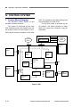
1. System Configuration
The figure below shows the system
configuration.
Computer
Network
Application software
Printer
Display
ISIS/TWAIN driver
Keyboard/
Mouse
Low level driver (LLD)
USB driver
DR-2020U
USB host
Figure 2-101
Item
Function
DR-2020U
Reading images and making output to computer
Computer
Controlling system
Application software
Saving and searching images
ISIS/TWAIN driver
Setting conditions and processing images
Low level driver (LLD)
Controlling DR-2020U (equivalent to firmware)
USB driver
Interface between LLD and USB host
USB host
Interface for image data input
Table 2-101
COPYRIGHT © CANON ELECTRONICS INC. 2009
CANON DR-2020U FIRST EDITION
2-1
CHAPTER 2 FUNCTION & OPERATION
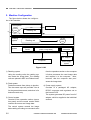
2. Machine Configuration
The figure below shows the configuration of this machine.
Feed system
Document
Feed
motor
Reading
system
Control
system
Reading unit
Flatbed
motor
Reading unit
Operation
section
Control section
(motor, image data)
DC/DC
converter
AC adapter
Computer
Power supply
system
Figure 2-102
1) Reading system
Using the reading units, the reading system reads the image data. The reading
units are placed in ADF and Flatbed units.
2) Feed system
Feeds documents from pickup to ejection.
Two document trays are provided. One is
for the general documents, and other is for
business cards only.
3) Control system
Consists of the operation section (operation panel) and the control section which
controls the motors and image data.
The control system controls the image
data reading according to commands sent
2-2
from the operation section or the computer.
It further processes the read image data
and outputs it to the computer. Note,
however, that the computer also processes the image data.
4) Power supply system
Consists of a packaged AC adapter,
DC/DC converters and regulators set on
the internal PCB.
The system generates DC power from AC
adapter, which is supplied to the individual
sections.
COPYRIGHT © CANON ELECTRONICS INC. 2009
CANON DR-2020U FIRST EDITION
CHAPTER 2 FUNCTION & OPERATION
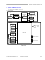
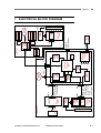
3. Outline of Electric Circuit
The figure below shows the outlines of
the block diagram.
ADF unit
Sensors (x5)
CCFL
Inverter
PCB
CCD PCB
ADF relay
PCB
CCD
Sensor
M
Feed motor
Clutch
Solenoid
Flatbed unit
Operation
PCB
M
Switches
(x13)
Flatbed
motor
LCD
Main PCB
Inverter
PCB
Power connector
CCD
PCB
C
C
F
L
CCD
USB connector
Sensor
Figure 2-103
COPYRIGHT © CANON ELECTRONICS INC. 2009
CANON DR-2020U FIRST EDITION
2-3
CHAPTER 2 FUNCTION & OPERATION
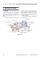
II. READING SYSTEM
1. Outline
The reading units are placed in the
flatbed unit and ADF unit. In the flatbed
scanning, the reading unit in the flatbed unit
named lower reading unit is used for its
reading.
In the feeder scanning, the lower read-
ing unit is used for the front side reading,
and the reading unit in the ADF unit named
upper reading unit is used for the back side
reading. For the business card scanning, it is
reversed on the side.
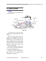
The cross section of the reading system
is shown below.
Roller unit
Feed unit
Upper reading unit
Document
Reading glass
(feeder)
Reading glass
(flatbed)
Lower reading unit
Figure 2-201
2-4
COPYRIGHT © CANON ELECTRONICS INC. 2009
CANON DR-2020U FIRST EDITION
CHAPTER 2 FUNCTION & OPERATION
2. Flatbed
The figure below shows a cross section
of the lower reading unit. And the basic of
reading is described using this figure.
Shading sheet Document
Lamp
Reading glass
Mirror
Mirror
Lower reading unit
CCD
Lens
Figure 2-202
While the lower reading is moving, the
light emitted by the light source (fluorescent
lamp) passes through the reading glass, is
reflected by the document, then goes into
the reading unit. In the reading unit, the
incident light is reflected by five mirrors,
passes through a lens and reaches the CCD.
The CCD PCB converts the data to analog
signals, which are output to the main PCB.
As the light source, the machine uses a
cold cathode fluorescent lamp (CCFL),
which is generally called a fluorescent lamp.
The CCD is a three-color (R/G/B), three-line
sensor having a picture element density of
1200 dpi and an effective picture element of
10680 pixels. It is noticeable that the CCD
can make analog grayscale outputs besides
the R/G/B outputs. And an actual output
density is 600 dpi or 300 dpi.
The shading sheet is placed between
the reading glass and the flatbed cover, so
COPYRIGHT © CANON ELECTRONICS INC. 2009
that it is aligned to the home position of the
reading unit. The reading unit has a sensor
to detect the home position.
After such events as the machine power
is turned on, the driver setting is changed
and an error occurs, the machine reads the
shading sheet data and calculates the corrected values prior to scanning.
In addition, the machine reads the
shading sheet data prior to each scanning
operation to ensure the light intensity from
the fluorescent lamp. In case of low or unstable light intensity from the fluorescent
lamp, which may be encountered after the
machine power is turned on and the machine is resumed from the sleep mode, the
machine goes into the warming up state,
showing “Warming up” on the display, and
does not carry out scanning before resuming
the normal condition.
CANON DR-2020U FIRST EDITION
2-5
CHAPTER 2 FUNCTION & OPERATION
The figure below shows the driving system for the lower reading unit.
Lower reading unit
Guide shaft
Timing belt for
reading unit
Flatbed motor unit
Figure 2-203
To move the lower reading unit, the
machine has a flatbed motor unit, a timing
belt and a pair of guide shafts.
For the flatbed scanning, the document
does not move and the lower reading unit
moves. For the feeder scanning, on the
other hand, the lower reading unit is placed
at a specific position and the document
moves.
2-6
COPYRIGHT © CANON ELECTRONICS INC. 2009
CANON DR-2020U FIRST EDITION
CHAPTER 2 FUNCTION & OPERATION
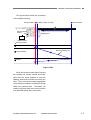
The figure below shows the movement
at the flatbed scanning.
Home position
Home position
sensor
Leading edge of image
Return position
Reading unit
Flatbed motor
Scanning starts
Home position
Move of reading unit
Image reading
Return
Figure 2-204
When the scanning start signal is output,
the reading unit moves forward and backward from the home position to read the
shading sheet and reconfirm the home position. Then it moves at a speed appropriate
to the reading conditions, reading the image
within the required area. Thereafter, the
reading unit goes back to the home position
at a specified speed, then stops there.
COPYRIGHT © CANON ELECTRONICS INC. 2009
CANON DR-2020U FIRST EDITION
2-7
CHAPTER 2 FUNCTION & OPERATION
3. Feeder
In the feeder scanning, the lower reading unit is used for the front side reading,
and the upper reading unit is used for the
back side reading. The general specifications and compositions of the upper reading
unit are the same as the lower reading unit.
Shading sheet for lower unit
Position at documet reading
Shading sheet for upper unit
Background sheet for upper unit
Position at shading sheet reading
Figure 2-205
In the same way as the flatbed scanning,
when the scanning start signal is output, the
lower reading unit reads the shading sheet
and reconfirms the home position. Then it
moves to the front side reading position and
reads the image there.
On the top surface of the lower reading
unit, a white long sheet and black long sheet
are attached. The white one is used for the
shading, and the black one is used for the
background for the upper reading unit.
Therefore, the upper reading unit can
read the shading sheet at the same time as
the lower reading unit reads the shading
sheet. And the upper reading unit can read
the back side of document at the same time
as the lower reading unit read the front side
of document.
2-8
After completing image reading, the
lower reading unit goes back to the home
position.
COPYRIGHT © CANON ELECTRONICS INC. 2009
CANON DR-2020U FIRST EDITION
CHAPTER 2 FUNCTION & OPERATION
III. FEED SYSTEM
1. Outline
The figure below shows a sectional view
of the feed system.
Roller unit
Separation roller
Middle roller
Documents
Pickup roller
Separation Pad
Feed roller
Eject roller
Figure 2-301
The feed system consists of a document
setting section, a feed section and an eject
section.
After fed by the pickup roller, the
documents are separated one sheet by
another by the separation roller and the
separation pad. The unit consisting of these
rollers is called the roller unit. The feed roller
feeds the document to the image reading
position and lastly the eject roller ejects the
document. These rollers are driven by the
feed motor and the gears.
To control the operation, the feed section has sensors, which detect the document
by the shift of the detection lever.
There is a document set section for
business cards on the left side of the above
figure. Refer to the “5. Business Card
Feeding” section for details.
COPYRIGHT © CANON ELECTRONICS INC. 2009
CANON DR-2020U FIRST EDITION
2-9
CHAPTER 2 FUNCTION & OPERATION
2. Pickup Operation
The figure below shows the appearance
of the pickup side of the feed system.
Document stopper
Roller unit
Document stopper
Figure 2-302
When execute the feeder scanning, the
roller unit will rise an angle, then put document in the document feed tray, for preventing document go into the pickup roller
too deep, the document stoppers will stop
document. When start a feeding, the roller
unit will go down and the document will be
forwarded and the document stoppers down
to let document go through it.
2-10
COPYRIGHT © CANON ELECTRONICS INC. 2009
CANON DR-2020U FIRST EDITION
CHAPTER 2 FUNCTION & OPERATION
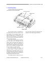
3. Feed Operation
The figure below shows the appearance
of the feed side of the feed system.
Document sensor
Middle sensor
Registration sensor
Figure 2-303
The document sensor is assembled in
the pickup side as the first sensor for the
feed system. The document sensor can
detect whether there is document or not.
When put the document in the document
tray, the document will push the sensor arm
down and start detecting.
When feeder scanning starts, the pickup
roller will pick up one document into the
feeder, then the document will transport to
the inside more. When the document is
detected by the registration sensor, the feed
motor will go forward the specified steps
then the reading unit starts reading.
The first document tail comes off
document sensor, if another document is
detected by the document sensor, the following document will continue to transport to
the feeder. It will repeat until no document is
detected by the document sensor.
The middle sensor is used for the con-
COPYRIGHT © CANON ELECTRONICS INC. 2009
trol at the Scan Ahead OFF setting and the
detection for the short length document.
CANON DR-2020U FIRST EDITION
2-11
CHAPTER 2 FUNCTION & OPERATION
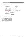
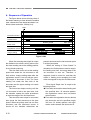
4. Sequence of Operation
The figure below shows a timing chart of
the feeder scanning in case where the machine
uses a document of two sheets and basic conditions (black and white, 300 dpi, A4).
Start
End
Document sensor
Reading position
H/P
Flatbed motor
Reading speed
Eject speed
Feed motor
1st document
2nd document
Registration sensor
Front, Back side
Front, Back side
Image reading
Figure 2-304
When the scanning start signal is output,
the flatbed motor starts running and moves
the lower reading unit to the reading position
for the feeder scanning.
Then the feed motor runs at the reading
speed and sends the 1st document to the
feed section. Image reading starts after the
registration sensor is set on and the specified length of document is fed. The lower
reading unit reads the front side of the
document and the upper reading unit reads
the back side.
The feed motor keeps running until the
1st document is fed to the eject area. And
the machine repeats the same procedures
to read the image of the 2nd document.
Then the feed motor stops for a moment,
then ejects the 2nd document at the eject
speed. When the pickup area has no more
document and the document sensor is
turned off, the machine determines the
2-12
present document as the last one and ejects
it at the eject speed.
When the setting of “Scan Ahead” is
cancelled, the 2nd document need to stop in
the feeding area until the image data of the
1st document is sent out. Therefore, a
magnetic clutch is turned on, and then the
rollers in feeding area excepting the feed
roller are stopped to stop the 2nd document.
Error signal “Paper Jam” is output in the
following events.
Even after the machine starts feeding and
the specified time; 30 seconds passes,
the registration sensor does not detect
the document.
Even after the registration sensor detects
the document and the specified length;
406 mm (16 inches) passes, the registration sensor detects the document till.
COPYRIGHT © CANON ELECTRONICS INC. 2009
CANON DR-2020U FIRST EDITION
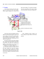
CHAPTER 2 FUNCTION & OPERATION
5. Business Card Feeding
The figure below shows a sectional view
of the business card feed system.
Pickup roller Separation roller
(business card) (business card)
Eject roller
Business cards
Feed roller
Pad
Figure 2-305
When the business cards are put in a
business card feeder then the pickup roller
will pick up one business card into the feeder
then the separation roller will separate the
business card and feed the business card to
the feed roller.
The feed roller will transport the business
card to a scanning line, at the same time the
lower reading unit will go to the feeder scanning line as the same as the feeder scanning,
then start reading the business card data.
The upper reading unit reads the front side of
the business card, and the lower reading unit
reads the back side.
And then the eject roller will eject the
business card out.
When the business card feeder has
opened, a business card sensor has detected it. And then the clutch and solenoid
operate to stop the rollers in the feeding area
excepting the feed roller, and keep it.
COPYRIGHT © CANON ELECTRONICS INC. 2009
CANON DR-2020U FIRST EDITION
2-13
CHAPTER 2 FUNCTION & OPERATION
IV. CONTROL SYSTEM
1. Control Block Diagram
PCB. The operation panel and reading units
are connected to the main PCB.
The 24 VDC power is provided by the
AC adaptor. The USB connector on Main
PCB is to connect the computer using the
USB cable.
The electrical control system of this
machine is shown as below.
The system is composed by the main
PCB, operation panel, two reading units and
two motors mainly. And this system is controlled by the scanner controller on the main
Sensors
ADF unit
Flatbed
Motor
ADF Relay PCB
Clutch
Feed
Motor
Solenoid
Upper
Reading
Unit
Main PCB
Operation
Panel
Motor
Driver
(U3)
SDRAM
(IC8, 9)
Motor
Driver
(U7)
Scanner
Controller
(U4)
USB
X’tal
Lower
Reading
Unit
AFE
(U2)
DC Power
Supply
24 VDC AC
Adaptor
Multiplexer
(U1)
Figure 2-401
2-14
COPYRIGHT © CANON ELECTRONICS INC. 2009
CANON DR-2020U FIRST EDITION
CHAPTER 2 FUNCTION & OPERATION
2. Image Processing
The figure below shows a block diagram
of image processing executed by this machine.
[This machine]
Main PCB
SDRAM (32 MB x 2)
Reading unit
(Upper, Lower)
Inverter
C
C
F
L
Analog processor
• Offset adjustment
• Gain adjustment
• A/D conversion
CCD
PCB
Controller
• CCLF lighting
control
• 16 bits to 8 bits
USB I/F
[Computer]
Resolution
conversion
Shading correction
Color
Grayscale
Data after shading correction
Color correction
(3-dimension)
Other processes
• Size detection
• Black border removal
• Punch hole removal
• Others
1-dimensional gamma correction
Edge emphasis
Binarizing
Color
Grayscale
Binary
Data after image processing
Figure 2-402
COPYRIGHT © CANON ELECTRONICS INC. 2009
CANON DR-2020U FIRST EDITION
2-15
CHAPTER 2 FUNCTION & OPERATION
Corresponding to the density of each
picture element, the CCD PCB outputs an
analog signal to the analog processor on the
main PCB.
The analog processor adjusts the offset
and the gain and then executes A/D conversion. Thereby the analog signal is converted to a 16bit digital signal. Then the
image data is output to the controller, where
it is tentatively saved in the SDRAM. This
16bit signal is converted to an 8bit signal at
this time. There are 2 SDRAMs, one for the
front side image, and another for the back
side.
The image data is then output to the
computer via the USB interface.
All the image processing executed by
this machine is as described above. Any
other image processing is carried out inside
the computer. Refer to the Figure 2-402 for
details. Inside the computer, the image is
processed as settings by the user.
This machine can output the resolution
of 600 dpi or 300 dpi. In case of the setting
resolution is 300 dpi or less, this machine
outputs 300 dpi data. And in case of the 400
dpi or 600 dpi, 600 dpi data is output. If the
smoothing is selected, the resolution is kept
at 600 dpi.
2-16
COPYRIGHT © CANON ELECTRONICS INC. 2009
CANON DR-2020U FIRST EDITION
CHAPTER 2 FUNCTION & OPERATION
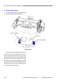
V. ELECTRICAL PARTS LAYOUT
CL1
SL1
PS2
PS1
UNT1
PS3
PS4
PS5
M1
UNT2
PCB3
PS7
PS6
M2
PCB1
PCB2
Figure 2-501
Unit
ADF unit
Flatbed unit
Name
Document sensor
Middle sensor
Registration sensor
Business card sensor
Feed cover sensor
ADF open sensor
Feed motor
Clutch
Solenoid
ADF relay PCB
Upper reading unit
Home position sensor
Flatbed motor
Main PCB
Operation PCB
Lower reading unit
Symbol
PS1
PS2
PS3
PS4
PS5
PS6
M1
CL1
SL1
PCB3
UNT1
PS7
M2
PCB1
PCB2
UNT2
Table 2-501
COPYRIGHT © CANON ELECTRONICS INC. 2009
CANON DR-2020U FIRST EDITION
2-17
CHAPTER 2 FUNCTION & OPERATION
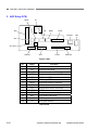
VI. PARTS LAYOUT ON PCB
1. Main PCB
CN2
CN1
CN3
J-USB1
J1
P1
Figure 2-601
No.
Name
Function
1
J-USB1
2
P1
3
CN3
Flatbed motor connector
4
CN2
Operation panel connector
5
CN1
Lower CCD connector
USB connector
ADF cable connector
Table 2-601
2-18
COPYRIGHT © CANON ELECTRONICS INC. 2009
CANON DR-2020U FIRST EDITION
CHAPTER 2 FUNCTION & OPERATION
2. Lower CCD PCB
S1
CN1
CCD unit
CN2
Note:Do not remove this PCB from the lower reading unit.
Figure 2-602
No.
Name
1
CN2
2
S1
3
CN1
Function
CCD FFC connector
Home position sensor
Inverter connector
Table 2-602
COPYRIGHT © CANON ELECTRONICS INC. 2009
CANON DR-2020U FIRST EDITION
2-19
CHAPTER 2 FUNCTION & OPERATION
3. ADF Relay PCB
S1
DES2
DS
SIG
CCD1
DES1
COVER
BIZ
SD
CLUTCH
CCD2
OUT
ADFMT
MOTOR
Figure 2-603
No.
Name
Function
1
BIZ
Business card sensor connector
2
SD
Solenoid connector
3
COVER
Feed cover sensor connector
4
MOTOR
Feed motor connector (OUT)
5
CCD1
CCD timing FFC connector
6
CCD2
CCD output FFC connector
7
DES1
Document sensor connector
8
DES2
Middle sensor connector
9
DS
10
CLUTCH
11
ADFMT
12
SIG
CCD timing connector
13
OUT
CCD output connector
14
S1
Registration sensor connector
Clutch connector
Feed motor connector (IN)
ADF open sensor
Table 2-603
2-20
COPYRIGHT © CANON ELECTRONICS INC. 2009
CANON DR-2020U FIRST EDITION
CHAPTER 3
DISASSEMBLY & REASSEMBLY
I.
ADF UNIT.................................................3-1
COPYRIGHT © CANON ELECTRONICS INC. 2009
II.
FLATBED UNIT ......................................3-10
CANON DR-2020U FIRST EDITION
CHAPTER 3 DISASSEMBLY & ASSEMBLY
I. ADF UNIT
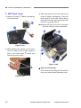
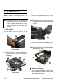
1. ADF Unit (Entire)
1 (with
1) Remove 2 screws {
a connector)
on the rear side and remove the connector
2.
{
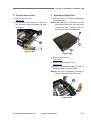
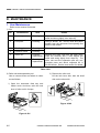
2. Pickup Tray Unit
1 , tilt the rear side
1) Open the feed cover {
2 inward, unhook the fitting parts
plate {
3 , and slide it to the front slightly. Then,
{
4 on the opposite
slide the fitting parts {
5.
side and remove the pickup tray unit {
Note:Since the fitting parts strike the part
marked with ¼, perform work to avoid
damage to them. This also applies
during assembly.
Figure 3-101
1 , lift it, and
2) Fully open the ADF unit {
remove it while removing the right and left
2.
hinges {
Figure 3-103
Note:Since other disassembling work may
become easier, this pickup tray unit
may be removed even if it is not specified in the procedure for this chapter.
Figure 3-102
Note:The machine in the figure for this
chapter may have a few difference with
the mass-production’s one.
COPYRIGHT © CANON ELECTRONICS INC. 2009
CANON DR-2020U FIRST EDITION
3-1
CHAPTER 3 DISASSEMBLY & REASSEMBLY
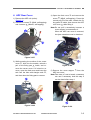
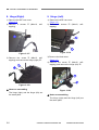
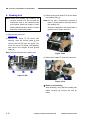
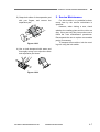
3. ADF Front Cover
1 (M3x8, self-tapping)
1) Remove 2 screws {
on the back side.
1 and remove the
3) Open the feed cover {
2 (M3x8, self-tapping). Press the
screw {
3 of the side, unhook the fitcentral part {
4 inside, then remove the ADF
ting parts {
5 while lifting it.
front cover {
Note:When the ADF front cover is removed,
the eject extension cover is detached.
Figure 3-104
2) While pressing the surface of the corner
1 , slide it to the outside, unhook 2
cover {
2 inside, and
pairs of the fitting parts {
remove the corner cover.
Figure 3-106
Notes on assembling
First, assemble the fitting parts of the ADF
front cover and the eject extension cover.
Figure 3-105
3-2
COPYRIGHT © CANON ELECTRONICS INC. 2009
CANON DR-2020U FIRST EDITION
CHAPTER 3 DISASSEMBLY & ASSEMBLY
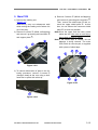
4. ADF Rear Cover
1) Remove the ADF unit (entire).
(Page 3-1)
1 (M3x8, self-tapping)
2) Remove 2 screws {
2 (M4x20, self-tapping).
and 4 screws {
1 and remove the
4) Open the feed cover {
2 (M3x8, self-tapping). Press the
screw {
3 of the side, unhook the fitcentral part {
4 inside, then remove the ADF
ting parts {
5 while lifting it.
rear cover {
Note:Do not pull it excessively because a
cover stopper is connected to it.
When the ADF rear cover is removed,
the eject extension cover is detached.
Figure 3-107
3) While pressing the surface of the corner
1 , slide it to the outside, unhook a
cover {
2 inside, and repair of the fitting part {
move the corner cover. If it is hard to remove, open the feed cover and insert the
3,
tool from the hole with triangle mark {
and then down the fitting part to remove.
Figure 3-109
1 from the
5) Remove the cover stopper {
ADF rear cover.
Note:Take care of it not to break, a tweezers
can use if necessary. And this step 5
can be done before step 4.
Figure 3-108
COPYRIGHT © CANON ELECTRONICS INC. 2009
Figure 3-110
CANON DR-2020U FIRST EDITION
3-3
CHAPTER 3 DISASSEMBLY & REASSEMBLY
5. Business Card Tray Unit
1 , press
1) Open the business card tray unit {
2 and remove
and widen 2 guide plates {
3.
the ends of the roller shaft {
Note:This guide plates are placed into the
grooves.
6. Business Card Roller
1) Remove the business card tray unit.
(Page 3-4)
1 , remove the
2) Remove one of the E-rings {
2 and business card roller {
3.
roller shaft {
Figure 3-113
Figure 3-111
1
2) Pull the business card tray unit {
2
straight, unhook 2 pairs of fitting parts {
and remove the business card tray unit.
Notes on assembling
Install the timing belt in the business card
roller.
Figure 3-112
3-4
COPYRIGHT © CANON ELECTRONICS INC. 2009
CANON DR-2020U FIRST EDITION
CHAPTER 3 DISASSEMBLY & ASSEMBLY
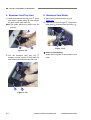
7. Feed Cover
1) Remove the ADF rear cover.
(Page 3-3)
2) Remove the business card tray unit.
(Page 3-4)
1.
3) Remove the connector {
Notes on assembling
1 must be outThe business card roller {
side the feed cover. Insert the above shaft
5 in the step 4, close the feed
fitting parts {
cover, and hook the fitting parts in the reverse order of the removal.
Figure 3-116
Figure 3-114
1 , tilt the rear side,
4) Open the feed cover {
2 , fitting parts {
3,
unhook the fitting parts {
4 in this order, and finally
and fitting parts {
5 of the
unhook the shaft fitting parts {
front side, and remove the feed cover.
Figure 3-115
COPYRIGHT © CANON ELECTRONICS INC. 2009
CANON DR-2020U FIRST EDITION
3-5
CHAPTER 3 DISASSEMBLY & REASSEMBLY
8. Hinge (Right)
9. Hinge (Left)
1) Remove the ADF rear cover.
(Page 3-3)
1 (M4x12, self2) Remove 2 screws {
tapping).
1) Remove the ADF rear cover.
(Page 3-3)
1 (M4x12, self2) Remove 2 screws {
tapping).
Figure 3-117
Figure 3-119
1 (M4x12, self3) Remove the screw {
2.
tapping) and remove the hinge (right) {
3) Remove the feed motor.
(Page 3-7)
1 (M4x12, self4) Remove the screw {
2.
tapping) and remove the hinge (left) {
Figure 3-118
Notes on assembling
The hinge (right) and the hinge (left) are
the same parts.
3-6
Figure 3-120
Notes on assembling
The hinge (right) and the hinge (left) are
the same parts.
COPYRIGHT © CANON ELECTRONICS INC. 2009
CANON DR-2020U FIRST EDITION
CHAPTER 3 DISASSEMBLY & ASSEMBLY
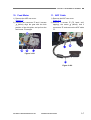
10. Feed Motor
11. ADF Cable
1) Remove the ADF rear cover.
(Page 3-3)
1 and 2 screws
2) Remove the connector {
2 (M3x4), align the gear with the hole
{
position of the side plate, and pull out the
3 straight.
feed motor {
1) Remove the ADF rear cover.
(Page 3-3)
1 (TP head, self2) Remove 2 screws {
2 (M3x4), and 3
tapping), the screw {
3 and remove the ADF cable
connectors {
4.
{
Figure 3-121
Figure 3-122
COPYRIGHT © CANON ELECTRONICS INC. 2009
CANON DR-2020U FIRST EDITION
3-7
CHAPTER 3 DISASSEMBLY & REASSEMBLY
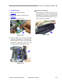
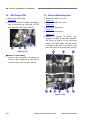
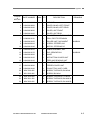
12. ADF Relay PCB
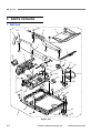
13. Feed and Reading Unit
1) Remove the ADF cable.
(Page 3-7)
1 (M3x8, self-tapping)
2) Remove 3 screws {
2 (including 2 FFCs)
and 10 connectors {
3.
and remove the ADF relay PCB {
1) Remove the ADF front cover.
(Page 3-2)
2) Remove the ADF rear cover.
(Page 3-3)
3) Remove the feed cover.
(Page 3-5)
4) Remove the feed motor.
(Page 3-7)
1 (M3x8, self5) Remove 5 screws {
2 (flat head, stepped),
tapping), 2 screws {
3 (M3x4) for the grounding
the screw {
cable of the ADF cable and the cables
4 , and
connected to the ADF relay PCB {
5.
then remove the feed and reading unit {
Figure 3-123
Notes on assembling
Connect the connectors (excepting the
FFCs) to the receptacles on the PCB to
meet the same color and pin numbers.
Figure 3-124
3-8
COPYRIGHT © CANON ELECTRONICS INC. 2009
CANON DR-2020U FIRST EDITION
CHAPTER 3 DISASSEMBLY & ASSEMBLY
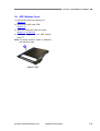
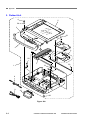
14. ADF Bottom Cover
1) Remove the feed and reading unit.
(Page 3-8)
2) Remove the ADF relay PCB.
(Page 3-8)
3) Remove the hinges (left) and (right).
(Page 3-6), (Page 3-6)
4) The remaining part is the ADF bottom
1.
cover {
Note:The black pressure board is attached
with adhesive tape.
Figure 3-125
COPYRIGHT © CANON ELECTRONICS INC. 2009
CANON DR-2020U FIRST EDITION
3-9
CHAPTER 3 DISASSEMBLY & REASSEMBLY
II. FLATBED UNIT
Note:For details on removal of the ADF unit
(entire), refer to page 3-1.
Note:Since dust may enter the inside easily
when the top cover is removed, perform
work in a place where there is as little
dust as possible to prevent dust from
entering.
3) Hold the hinge insertion hole with a hand
1 from the base
and pull off the top cover {
side.
Note:For details on how to unhook the front
fitting parts, refer to the following procedure.
1. Top Cover
1 of the
1) First release the lock lever {
reading unit.
Figure 3-203
4) Since the front side is fitted with the front
1 , remove it while tilting the
lower cover {
2 slowly.
top cover {
Note:Prevent damage to the fitting parts with
the front lower cover.
Figure 3-201
1 with a tool with a flat,
2) Pull out 4 caps {
thin tip and remove 4 inner screws (M3x8,
self-tapping).
Figure 3-204
Figure 3-202
3-10
Notes on assembling
If there is any dust inside, remove it and
then install the top cover. And clean a back
side of the reading glass.
COPYRIGHT © CANON ELECTRONICS INC. 2009
CANON DR-2020U FIRST EDITION
CHAPTER 3 DISASSEMBLY & REASSEMBLY
2. Front Lower Cover
1) Remove the top cover.
(Page 3-10)
1 to the front
2) Pull the front lower cover {
and remove it while unhooking the inner
fitting parts.
3. Operation Panel Unit
1 (M3x8, self-tapping)
1) Remove 2 screws {
on the back side.
Note:If the flatbed unit is turned over after
removing the top cover, one side of the
reading unit falls. Therefore, first remove the screws on the back side.
Figure 3-205
Figure 3-206
2) Remove the top cover.
(Page 3-10)
3) Remove the front lower cover.
(Page 3-11)
1 and re4) Remove the operation panel {
move the cable on the back side.
Note:Do not pull it excessively because a
cable is connected to the back side.
Figure 3-207
COPYRIGHT © CANON ELECTRONICS INC. 2009
CANON DR-2020U FIRST EDITION
3-11
CHAPTER 3 DISASSEMBLY & REASSEMBLY
4. Reading Unit
Note:Handle the reading unit carefully. Do
not give a shock to it. Do not stain the
fluorescent tube or the reflection plate
at the place where the image is read,
and the black and white sheets. Prevent
dust from entering the inside.
1) Remove the top cover.
(Page 3-10)
1 (TP head, self2) Remove the screw {
2 and
tapping), slide the tension plate {
3 from the pulley. Reremove the belt {
4 (M3x8, self-tapping),
move the screw {
5 and ground
and remove the stopper {
6.
cable {
Note:The belt is fixed to the reading unit.
1 from the base
3) Remove the guide shaft {
2.
and reading unit {
Note:Do not pull it excessively because a
cable is connected to the back side of
the reading unit.
Grease is applied on the guide shaft. If
grease is on a finger, remove it.
Figure 3-209
1 from the connector.
4) Remove the cable {
Figure 3-208
Figure 3-210
Notes on assembling
After assembly, verify that the reading unit
slides correctly by moving the belt by
hand.
3-12
COPYRIGHT © CANON ELECTRONICS INC. 2009
CANON DR-2020U FIRST EDITION
CHAPTER 3 DISASSEMBLY & REASSEMBLY
5. Main PCB
1) Remove the reading unit.
(Page 3-12)
Alternatively, carry out subsequent work
while moving the reading unit to where it is
out of the way.
1 (M3x8, self-tapping)
2) Remove 2 screws {
2
and remove 2 grounding wire terminals {
3.
and support plate {
1 (M3x8, self-tapping)
4) Remove 5 screws {
2.
and remove 2 grounding wire terminals {
3 and reThen, remove the shield tape {
4 . At this
move the upper shield plate {
time, do not deform the connector shield
5 as much as possible.
plate {
Note:Since the upper and the lower shield
plates are thin, take care to avoid injury
due to their corners or edges.
Note:If the shield tape is reused, do not
damage it during removal. The main
PCB, which is a service part, is supplied
with a piece of shield tape.
Figure 3-211
3) To reduce deformation of parts in the fol1
lowing procedure, remove 2 screws {
(hexagon head) at the rear using a dedicated tool or pliers with a thin tip.
Figure 3-213
Figure 3-212
COPYRIGHT © CANON ELECTRONICS INC. 2009
CANON DR-2020U FIRST EDITION
3-13
CHAPTER 3 DISASSEMBLY & REASSEMBLY
1 , and relieve the cable
5) Remove 2 FFCs {
2 from the cable stoppers {
3.
{
Note:The connector for the FFC has a lock, it
needs to be opened before removing
the FFC. Refer to the figure below for
details.
Notes on assembling
1) The main PCB, which is a service part,
consists of a PCB body, a connector shield
plate, and a piece of shield tape. It does
not include 3 rubber sheets for radiation. If
the main PCB is replaced, use the parts
attached to the old main PCB. Refer to the
next item for details.
1 for radiation
2) Verify that 3 rubber sheets {
are placed on the specified ICs.
Locked connector
Opening
Opened connector
Figure 3-216
Figure 3-214
1 , pull out the con6) Tilt the main PCB {
nectors through the holes on the back and
remove the main PCB. At this time, the
2 is also deconnector shield plate {
tached.
3.
And remove the cable {
3) If the connector shield plate is deformed,
correct it manually. The connector shield
plate must contact the upper shield plate
without any gap.
Contact → OK
Open → NG
Figure 3-217
Figure 3-215
3-14
COPYRIGHT © CANON ELECTRONICS INC. 2009
CANON DR-2020U FIRST EDITION
CHAPTER 3 DISASSEMBLY & REASSEMBLY
4) The FFC must be inserted straightly into
the connector and the lock must be
closed.
1 so that it joins
6) Attach the shield tape {
the FFC shield part and the upper shield
plate.
Insert
Close
Figure 3-218
5) When assembling the upper shield plate,
do not deform the connector shield plate
as much as possible and both parts must
contact each other correctly after assembly. Assemble them, being careful not to
strike the end of the upper shield plate
against the component on the PCB.
1 at the rear contacts the outThe bend {
side of the lower shield plate.
Figure 3-220
7) When fixing the connector shield plate
with 2 screws (hexagon head), hold the
connector shield plate lightly with fingers
so that it does not lift.
Figure 3-219
COPYRIGHT © CANON ELECTRONICS INC. 2009
CANON DR-2020U FIRST EDITION
3-15
CHAPTER 4
INSTALLATION & MAINTENANCE
I.
INSTALLATION ........................................4-1
II.
PARTS REPLACEMENT..........................4-5
COPYRIGHT © CANON ELECTRONICS INC. 2009
III.
MAINTENANCE .......................................4-6
CANON DR-2020U FIRST EDITION
CHAPTER 4 INSTALLATION & MAINTENANCE
I. INSTALLATION
This machine can be installed by users.
For installation, refer to “Reference Guide”
packaged with the product. The installation
procedures are as follows.
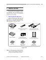
1. Checking the Accessories
Unpack the product and make sure that
it contains all of the following accessories.
Note that the packaged accessories may
differ depending on the sales region.
DR-2020U
USB Cable Type A/Type B
(Length: 1.8 m)
AC Adapter/Power Cord
(Connected length: 2.6 m)
Reference Guide
Registration Card
(U.S.A and Canada only)
Warranty Card
(U.S.A and Canada only)
Setup Disc
Adobe Acrobat
Setup Disc
Application
Software Disc
Figure 4-101
Note:It is recommended to keep the packaging and the packing materials for
storing and transporting the machine.
COPYRIGHT © CANON ELECTRONICS INC. 2009
CANON DR-2020U FIRST EDITION
4-1
CHAPTER 4 INSTALLATION & MAINTENANCE
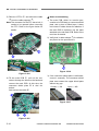
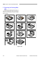
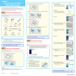
2. Removing the Packing Materials
Remove the scanner from the box, remove the orange tapes (▼) and protective
sheets from the scanner, and then release
the lock switch.
1)
2)
3)
4)
5)
6)
7)
8)
9)
10)
11)
Figure 4-102
4-2
COPYRIGHT © CANON ELECTRONICS INC. 2009
CANON DR-2020U FIRST EDITION
CHAPTER 4 INSTALLATION & MAINTENANCE
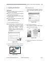
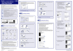
3. Installing the Software
Precautions
Install the software before connecting the
scanner to the computer.
Be sure to log on to the OS (Windows)
with administrator privileges.
Close all other applications before installing the software.
Check the operating environment of the
computer system.
Refer to user manual for details.
1) Turn the computer power on.
Note:If the scanner is connected and the
computer power is turned on before
the software is installed, the following
wizard screen appears. Click the
[Cancel] button to close the wizard.
Install the software before connecting
the scanner.
For Windows Vista
If the following screen appears, enter the
current administrator password and click.
[OK].
Figure 4-105
3) Click [Typical Installation].
All the software is installed. Refer to user
manual for the other options.
Figure 4-106
4) Follow the instructions on the screens to
complete.
Figure 4-103
2) Insert the Setup Disc into the CD drive.
The setup wizard automatically starts up.
Figure 4-104
COPYRIGHT © CANON ELECTRONICS INC. 2009
CANON DR-2020U FIRST EDITION
4-3
CHAPTER 4 INSTALLATION & MAINTENANCE
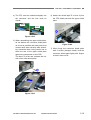
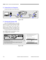
4. Connection to a Computer
Connect the cables as the figure below.
Figure 4-107
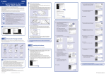
5. Turning the Scanner ON
Press the POWER button to turn the
scanner on, and the power indicator will light.
And an indication “Scan First” will be displayed in the display panel (LCD) after a
initial operation is done. For details of the
power link function, refer to the figure below.
To turn the scanner off, press and hold
the POWER button till an indication “Power
off” is displayed (for 2 seconds).
The plug-and-play function recognizes the
scanner, and the device driver is
automatically installed.
Power indicator
Power button
PC Power Link Function
The scanner’s power can be linked to the computer, allowing it to be turned ON/
OFF in accordance with the computer.
Under default settings, this function is disabled. To enable this function, display
the scanner’s properties from [Scanners and Cameras] in the Control Panel.
For details, refer to the User Manual.
Figure 4-108
4-4
COPYRIGHT © CANON ELECTRONICS INC. 2009
CANON DR-2020U FIRST EDITION
CHAPTER 4 INSTALLATION & MAINTENANCE
II. PARTS REPLACEMENT
1. Periodically Replaced Parts
This machine does not have any periodically replaced parts.
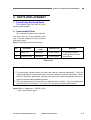
2. Consumable Parts
The consumable parts are as listed below. All of them are to be replaced by the
user. They are assigned as sales products
and service parts.
Note:This machine has no feed counter.
No.
Product
Code
Part Name
Expected life
1
Roller unit
4048B001
50,000 sheets
2
Separation pad
4048B002
50,000 sheets
Remarks
To be replaced when
cleaning does not clear
feed failures.
Table 4-201
Reference: Differences between periodically replaced parts and consumable parts
1. The periodically replaced parts are those that must be replaced periodically. They are
usually assigned as service parts, which must be replaced by service technicians. Note,
however, that those periodically replaced parts that have limited storage periods are assigned as commercially available products.
2. The consumable parts are those that are replaced when in failure. They are assigned as
products and/or service parts. The users or the service technicians replace them.
Note:Refer to “Appendix II. PARTS CATALOG” for the service parts.
COPYRIGHT © CANON ELECTRONICS INC. 2009
CANON DR-2020U FIRST EDITION
4-5
CHAPTER 4 INSTALLATION & MAINTENANCE
III. MAINTENANCE
1. User Maintenance
Refer to user manual for details.
1) List
No.
Location/Part
Item
Details
1
Main body
Cleaning
Wipe the surfaces with a cloth dipped into
water and wrung tightly, then wipe dry.
2
Feed path
Cleaning
Using a blower, etc., remove dust and paper
powder from the document feed opening and
inside of the feeder.
3
Reading glass
Cleaning
Wipe with a clean and dry cloth.
4
Pressure board
Cleaning
5
Roller unit
Cleaning,
replacement
6
Separation pad
Cleaning,
replacement
Remove the roller unit from the main body.
Wipe the surfaces with a cloth dipped into
water and wrung tightly, then wipe dry. The
roller unit and the separation pad are consumable parts and which expected life is
50,000 sheets. See the next section for details.
Table 4-301
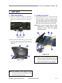
2) Roller unit and separation pad
How to remove them and where to clean
are as follows.
ii) Remove the roller unit.
Lift the lock lever side, then the shaft
side on the other side.
i) Open the document feed tray and
feeder cover. And then, raise the lock
lever of roller unit in 2 steps.
Figure 4-302
Figure 4-301
4-6
COPYRIGHT © CANON ELECTRONICS INC. 2009
CANON DR-2020U FIRST EDITION
CHAPTER 4 INSTALLATION & MAINTENANCE
iii) Grasp both sides of the separation pad
with your fingers, and remove the
separation pad.
Figure 4-303
2. Service Maintenance
For this machine, no periodical maintenance item by the service technicians is
specified.
However, when visiting a user, check
whether the reading glass and the roller are
dirty. If they are very dirty, instruct the user to
follow the “user maintenance” procedures.
Recommend the user to replace consumable
part(s) if necessary.
To transport this machine, lock the reading unit using the lock switch.
iv) Use a cloth dampened with water and
thoroughly wrung out to wipe the rollers
and separation pad clean.
Figure 4-304
COPYRIGHT © CANON ELECTRONICS INC. 2009
CANON DR-2020U FIRST EDITION
4-7
CHAPTER 5
TROUBLESHOOTING
I.
ERROR DISPLAY ....................................5-1
III.
OPERATION TROUBLESHOOTING .......5-6
II.
LIST OF ERRORS ...................................5-4
IV.
IMAGE TROUBLESHOOTING...............5-12
COPYRIGHT © CANON ELECTRONICS INC. 2009
CANON DR-2020U FIRST EDITION
CHAPTER 5 TROUBLESHOOTING
I. ERROR DISPLAY
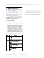
1. Operation Panel
The operation panel displays icons and
error messages. The details are as described below. Note that these messages
may not appear instantaneously.
For the detailed causes and countermeasures, refer to “III / IV. OPERATING /
IMAGE TROUBLESHOOTING”.
If the first display is not changed to the
next one, there must be a failure in the
USB cable connection, software installation, or others. Check and take measures.
1) Scanner recognition
After the power of this machine is turned
ON, only one icon with no message,
shown in No. 1-1 in the table below, is
displayed on the operation panel. If the
scanner is connected to a computer in
which software (including CaptureOnTouch) has been installed, the scanner is
recognized by the computer and the display changes. However, the display after
recognition is different according to conditions. Main displays are shown in No. 1-2
in the table below.
No.
Display
1-1
1-2
Table 5-101
COPYRIGHT © CANON ELECTRONICS INC. 2009
CANON DR-2020U FIRST EDITION
5-1
CHAPTER 5 TROUBLESHOOTING
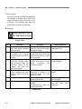
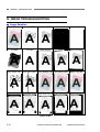
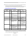
2) Error display
An error icon and message are displayed.
An example of display and a list of messages are shown below. The error icon is
the same. The message with long sentence will be scrolled for displaying.
Example
Paper jammed in scan
er; clear paper and pus
Figure 5-101
No.
Message
Meaning
Primary Measure
2-1
The document is jamming.
The roller and/or the separation pad are dirty.
User operation mistake. The
feeder scanning is executed
while the feed cover or ADF
unit is opened.
The double feed has occurred. And need to check
which
document
has
scanned correctly.
Clean the roller and the
separation pad.
2-6
Feeder is not connected.
User operation mistake.
Scanning or power on is
executed while the lock
switch is locked.
The lamp is not lit. Light intensity is abnormal.
The ADF cable is disconnected.
Communications with the
feeder impossible.
Release it, and scan
again.
2-5
Paper jammed in scanner; clear paper and push
STOP button.
The scanner feeder cover
or upper unit is open.
Close it, and push STOP
button.
A double paper-feed has
occurred. Please check
the document and the
scanned image on the
display and scan the
document again.
Release the lock switch.
After releasing the lock
switch, press the STOP
button.
Lamp Error
2-2
2-3
2-4
Close it, and scan again.
Clean the roller and the
separation pad.
Reset the power./Restart
the computer.
Power Off and connect
the ADF cable, then
power on.
Table 5-102
5-2
COPYRIGHT © CANON ELECTRONICS INC. 2009
CANON DR-2020U FIRST EDITION
CHAPTER 5 TROUBLESHOOTING
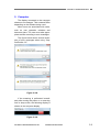
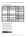
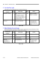
2. Computer
The display connected to the computer
shows error messages. Their contents differ
depending on the software being used.
Most errors are associated with users,
such as user operation mistakes and
document jams. The user must take appropriate actions according to error messages.
The figure below shows several examples of error messages when using “CapturePerfect 3.0”.
Figure 5-102
If the scanning is performed immediately after turning the power on or returning
from a sleep mode, the following display is
shown on the computer display.
Figure 5-103
COPYRIGHT © CANON ELECTRONICS INC. 2009
CANON DR-2020U FIRST EDITION
5-3
CHAPTER 5 TROUBLESHOOTING
II. LIST OF ERRORS
machine, the service technician is required
to operate in the same way as the user does
when checking the machine operation. Use
the driver packaged with the product and
appropriate application software.
The lists below give the major error
conditions and their causes. See the next
section for details of the causes and the
measures to be taken.
Because no service mode and no
software for servicing are available in this
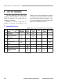
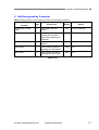
1. Operation Errors
Note: Major causes of each error are marked “X”.
No.
Cause
Error
System/
Software
Hardware
Connection
X
X
1
No power.
2
Not recognized by
computer.
X
3
Scanning does not
start.
X
4
Slow scanning
speed.
X
5
Motor does not work.
X
6
Document is not fed.
X
7
Jam/double feed
/skew.
X
Dirt
Document
Setting
X
X
X
X
X
X
X
X
Table 5-201
5-4
COPYRIGHT © CANON ELECTRONICS INC. 2009
CANON DR-2020U FIRST EDITION
CHAPTER 5 TROUBLESHOOTING
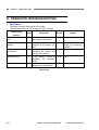
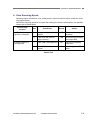
2. Images Errors
Note: Major causes of each error are marked “X”.
No.
Cause
Error
System/
Software
Hardware
Connection
Dirt
Document
Setting
1
Completely black/
completely white.
2
Too dark/too light.
3
Black borders
around image.
X
X
4
Image skews.
X
X
5
Moire on image.
X
X
6
Spots and streaks
on image.
7
Outer areas of image disappear.
X
X
X
X
X
X
X
X
X
Table 5-202
COPYRIGHT © CANON ELECTRONICS INC. 2009
CANON DR-2020U FIRST EDITION
5-5
CHAPTER 5 TROUBLESHOOTING
III. OPERATION TROUBLESHOOTING
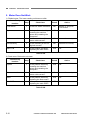
1. No Power
The power indicator and display do not light.
The fluorescent lamp of the reading unit does not light.
Cause/Faulty
location
Step
Check item
Result
Action
Connection of power
cord
1
Are the power cord and the
AC adapter connected?
NO
Connect properly.
AC power supply
voltage
2
Is the specified voltage
supplied to the power outlet?
NO
Explain user that the
trouble is not with this
machine.
Power cord,
AC adapter
3
Is the problem solved by
replacing the power cord
and the AC adapter?
YES
End.
Operation PCB
4
Is the problem solved by
replacing the operation
PCB?
YES
End.
Main PCB
5
Is the problem solved by
replacing the main PCB?
YES
End.
Table 5-301
5-6
COPYRIGHT © CANON ELECTRONICS INC. 2009
CANON DR-2020U FIRST EDITION
CHAPTER 5 TROUBLESHOOTING
2. Not Recognized by Computer
Note: Install the driver in the computer before connecting the scanner.
Cause/Faulty
location
Step
Check item
Result
Action
Connection of USB
cable
1
Is the USB cable connected?
NO
Connect properly.
System
2
Is the problem solved by
resetting the machine
power and restarting the
computer?
YES
End.
Scanner driver
3
Is the scanner driver installed?
NO
Install.
USB cable
4
Is the problem solved by
replacing the USB cable?
YES
End.
Main PCB
5
Is the problem solved by
replacing the main PCB?
YES
End.
Table 5-302
COPYRIGHT © CANON ELECTRONICS INC. 2009
CANON DR-2020U FIRST EDITION
5-7
CHAPTER 5 TROUBLESHOOTING
3. Scanning Does Not Start
Error message appears. The reading unit does not work.
Type of message
Step
Check item
Result
Action
Door open
1
Is the feeder cover or ADF
unit open?
YES
Close it, and push
STOP button.
Lock switch
1
Is the lock switch released?
NO
Release it, and push
STOP button.
Lamp Error
1
Is the lamp lit?
NO
Check the cable connection.
YES
Reset the power.
Restart the computer.
Check the shading
sheet.
Feeder disconnect
Job- related error
Error messages above
Main PCB
1
Is the ADF connector connected?
NO
Connect it.
1
Is the job properly set?
NO
Set properly.
YES
Check the system including the network.
Is the problem solved by
resetting the power and restarting the computer?
YES
End.
NO
Check the connection of
inside parts.
Is the problem solved by
replacing the main PCB?
YES
End.
2
3
Table 5-303
Scanning by the job function is impossible
if “Disable device events” is selected on
the Windows event setting screen.
Tens of seconds are required to warming
up the lamp after the machine power is
turned on or the machine is resumed from
the sleep mode. This is not a failure. By
the Windows power control setting screen,
however, the user can change the time
before the sleep mode is on. Refer to the
user manual for details.
Figure 5-301
5-8
COPYRIGHT © CANON ELECTRONICS INC. 2009
CANON DR-2020U FIRST EDITION
CHAPTER 5 TROUBLESHOOTING
4. Slow Scanning Speed
Selecting higher resolutions, color setting and/or special functions further makes the scanning speed slower.
Should the scanning speed be too slow after taking all of these considerations, the possible
causes are as listed below.
Cause/Faulty
location
Insufficient memory
capacity in computer
Hi-Speed USB2.0 is
not supported
Step
Check item
Result
Action
1
Is any other application activated?
YES
Close unnecessary applications.
2
Is the hard disk short of
empty memory?
YES
Increase empty memory
of the hard disk.
1
Is the USB card supported?
NO
Use a recommended
USB card.
2
Is the USB cable supported?
NO
Use a supported USB
cable.
Table 5-304
COPYRIGHT © CANON ELECTRONICS INC. 2009
CANON DR-2020U FIRST EDITION
5-9
CHAPTER 5 TROUBLESHOOTING
5. Motor Does Not Work
1) Flatbed motor: The lower reading unit does not slide.
Cause/Faulty
location
Step
Check item
Result
Action
Lock Switch
1
Is the lock switch released?
NO
Release it, and push
STOP button.
System
2
Is the problem solved by
resetting the machine
power and restarting the
computer?
YES
End.
Cable connection
3
Is the connection of the
motor cable correct?
NO
Connect it correctly.
Belt assembly
4
Is the assembly of the timing belt correct?
NO
Assemble it correctly.
Main PCB
5
Is the problem solved by
replacing the main PCB?
YES
End.
Table 5-305
2) Feed motor: Rollers do not rotate.
Cause/Faulty
location
Step
Check item
Result
Action
System
1
Is the problem solved by
resetting the machine
power and restarting the
computer?
YES
End.
Cable connection
2
Is the connection of the
motor cable correct?
NO
Connect it correctly.
Motor
3
Is the problem solved by
replacing the feed motor?
YES
End.
Main PCB
4
Is the problem solved by
replacing the main PCB?
YES
End.
Table 5-306
5-10
COPYRIGHT © CANON ELECTRONICS INC. 2009
CANON DR-2020U FIRST EDITION
CHAPTER 5 TROUBLESHOOTING
6. Document is Not Fed
Document is not fed at all. Document cannot be detected.
Error message “No page was found in the feeder” appears on the computer display.
Cause/Faulty
location
Step
Check item
Result
Action
Scanner setting
1
Is the “Paper Source” properly set? (Auto/Feeder)
NO
Properly set.
Document sensor
2
Does the document sensor
lever normally function?
NO
Check the move of the
lever and replace the
feed & reading unit if
necessary.
3
Is the document sensor
properly connected?
NO
Properly connect.
Table 5-307
7. Document is Not Properly Fed (Jam/Double Feed/Skew)
Document is wrinkled or folded. Double feed or skew occurs.
Document feed stops.
Cause/Faulty
location
Step
Check item
Result
Action
Document
1
Does the document meet
the specifications?
(Size, thickness, quality,
fold, etc.)
NO
Ask user to use documents that meet the
specifications. Ask
user to use the flatbed.
Document setting
2
Is the document properly
set?
(Curled, stuck, slant documents, misuse of document
guide, etc.)
NO
Properly set document.
Roller unit,
Separation pad
3
Are they properly mounted?
NO
Properly mount.
4
Are the surfaces clean?
NO
Clean or replace the
roller unit and/or the
separation pad.
Feed path
5
Are the surfaces contacting
the documents smooth?
(Dirt, damages, burrs, etc.)
NO
Clean there properly.
Feed & reading unit
6
Is the feed & reading unit
properly mounted?
NO
Mount it properly.
7
Is the problem solved by
replacing the feed & reading
unit?
YES
End.
Table 5-308
COPYRIGHT © CANON ELECTRONICS INC. 2009
CANON DR-2020U FIRST EDITION
5-11
CHAPTER 5 TROUBLESHOOTING
IV. IMAGE TROUBLESHOOTING
Image Samples
Original
Normal (FB)
Normal (ADF)
Too dark
Too light
Black border
Dirty glass (FB)
Completely black Completely white
Skew
Skew correction
Dirty glass (ADF) Dirty shading (FB) Dirty shading (ADF)
Moire (100 dpi)
Special document Automatic sizing Black border removal Skew correction-1 Skew correction-2
Figure 5-401
5-12
COPYRIGHT © CANON ELECTRONICS INC. 2009
CANON DR-2020U FIRST EDITION
CHAPTER 5 TROUBLESHOOTING
Note:Depending on the type of image and on the setting, document reproducibility might be poor.
In such a case, the image may be improved by changing the setting items.
This machine has the lower reading unit and upper one. Therefore, if only the image on the
same side is bad, the cause is in the reading unit for that side or a part related to it.
1. Completely Black/Completely White
Scanned image is completely black, completely white or has black stripes only.
Cause/Faulty
location
Step
Check item
Result
“Brightness” setting
1
Is the “Brightness” properly
set?
NO
Change the setting.
Adjust the “Contrast” in
addition if necessary.
“Paper Source” setting
2
Is the “Paper Source” properly set?
Completely black image
results from selecting flatbed with no document set
there.
NO
Change setting.
ADF cable connection
3
Is the ADF cable connected?
NO
Connect.
See note below.
Lock switch position
4
Is the lock switch released?
NO
Release.
See note below.
System
5
Is the problem solved by
resetting the machine
power and restarting the
computer?
YES
End.
NO
Possibly the machine or
the software is faulty.
Carry out check items
listed in “III. OPERATION
TROUBLESHOOTING”.
See note below.
6
Is the connection of the
cable correct?
NO
Connect it properly.
7
Is the problem solved by
replacing the reading unit?
*The feed & reading unit for
upper reading unit.
YES
End.
8
Is the problem solved by
replacing the main PCB?
YES
End.
Reading unit
Main PCB
Action
Note: Self diagnosis is executed prior to commencement of first scanning after the machine power
is turned on. Should an error be found at this time, the machine gives an error message.
Thereafter, however, the error message may not be shown and the scanner may only make
an output of completely black or completely white image.
Table 5-401
COPYRIGHT © CANON ELECTRONICS INC. 2009
CANON DR-2020U FIRST EDITION
5-13
CHAPTER 5 TROUBLESHOOTING
2. Too Dark/Too Light
Image does not look appropriate due to improper brightness.
Cause/Faulty
location
Step
Check item
Result
Action
“Brightness” setting
1
Is the “Brightness” properly
set?
The brightness should be
set to “Auto” in ordinary
case but may be required to
change according to the
type of document.
NO
Change the setting.
Adjust the “Contrast” in
addition if necessary.
Dark background
document
2
Is the “Advanced Text Enhancement” selected?
NO
Select.
Dark background is
eliminated and the
scanned image looks
better.
Table 5-402
3. Black Borders Around Image
Black borders appear around the images. However, that borders having a thickness of about
1 mm are within the specifications, so they are not a failure.
Cause/Faulty
location
Step
Check item
Result
Action
“Page Size” setting
1
Is the “Page Size” properly
set?
NO
Change the setting.
Document setting
2
Is the document set at the
correct position?
NO
Set at the correct position.
Setting of
“Auto-detection” for
paper size or
“Border Removal”
3
Is “Auto-detection” or “Border Removal” set?
NO
Set.
Black border can be
removed by image
processing.
Table 5-403
5-14
COPYRIGHT © CANON ELECTRONICS INC. 2009
CANON DR-2020U FIRST EDITION
CHAPTER 5 TROUBLESHOOTING
4. Image Skews
If the document is set slanting for flatbed scanning or skews when fed for feeder scanning,
then the image skews.
Cause/Faulty
location
Step
Check item
Result
Action
Document setting
1
Is the document properly
set?
NO
Properly set.
“Deskew” setting
2
Is the “Deskew” set?
NO
Set.
Slant can be corrected
by image processing.
Document feeding
3
Is the document fed
straight?
NO
Carry out check items
listed in “III. OPERATION
TROUBLESHOOTING
7. Document is Not
Properly Fed”.
Table 5-404
5. Moire on Image
Moire is likely to appear when a photograph is color scanned with a low resolution from a
magazine or a catalog.
When the “Color Smoothing” is set on, the averaging function converts the resolution for the
data read with a resolution of 600 dpi, suppressing occurrence of moire.
Cause/Faulty
location
“Color Smoothing” setting
Step
1
Check item
Is the “Color Smoothing”
set?
Result
Action
NO
Set.
YES
Heighten the resolution.
Table 5-405
COPYRIGHT © CANON ELECTRONICS INC. 2009
CANON DR-2020U FIRST EDITION
5-15
CHAPTER 5 TROUBLESHOOTING
6. Spots and Streaks on Image
If the reading glass surface is dirty when the flatbed scanning is used, the state of the spot on
the glass (shape and color) appears on the scanned image. In case of the feeder scanning,
spots on the feed system including the feed roller etc. appear on the document or those on
the reading glass for the feeder that make streaks in the feed direction on the scanned image.
On the other hand, white streaks appearing on the scanned images for both flatbed and
feeder scanning are caused by dirty shading sheet in most cases. In particular, if white
streaks appear outstanding in a slightly light area on a color and gray image, it can be said
that it is caused by dirty shading sheet.
Cause/Faulty
location
Step
Check item
Result
Action
Roller unit and separation pad (for feeder
scanning)
1
Are the surfaces clean?
NO
Clean or replace the
roller unit and/or the
separation pad.
Feed unit (for feeder
scanning)
2
Is the feed path clean?
NO
Clean.
Reading glass
3
Are the reading glasses
clean?
(for both flatbed and feeder
scanning)
NO
Clean.
Replace the feeder
cover unit if scratches
are found on the back
surface.
Shading sheet
4
Are the shading sheets
clean?
(for both flatbed and feeder
scanning)
NO
Clean.
YES
Clean the dust on the
entrance area of the
reading unit, or replace
the reading unit.
Table 5-406
7. Outer Areas of Image Disappear
When scanning a document with black or deep color outer areas, and selecting the
“Auto-detection,” the “Deskew” or the “Border Removal” may cause the outer areas to disappear from the scanned image.
Cause/Faulty
location
Document
Step
Check item
Result
1
Is there any black or deep
color on the document outer
areas?
YES
Action
Disable the functions
such as the
“Auto-detection”.
Table 5-407
5-16
COPYRIGHT © CANON ELECTRONICS INC. 2009
CANON DR-2020U FIRST EDITION
APPENDIX
I.
ELECTRICAL BLOCK DIAGRAM ........... A-1
COPYRIGHT © CANON ELECTRONICS INC. 2009
II.
PARTS CATALOG ................................... A-2
CANON DR-2020U FIRST EDITION
CANON DR-2020U FIRST EDITION
CN2
16pin
LCD FFC
CN1
Flatbed unit
CCFL
COPYRIGHT © CANON ELECTRONICS INC. 2009
Lower CCD
PCB
CCD
Home
sensor
(S1)
CN1
Inverter
PCB
Operation
PCB
(SW1-13)
CN2
CN1
CCD timing
CCD output signal
Inverter control
Power
Home signal
26pin FFC
CN2
Key button signal
LCD control timing
9pin FFC
CN2
Multiplexer
(U1)
SDRAM
(IC8,9)
Motor
Driver
(U3)
CN3
Flatbed
Motor
AFE
(U2)
Scanner
Controller
(U4)
P1
Main PCB
DC Power
Supply
X’tal
Motor
Driver
(U7)
Solenoid
Clutch
JADF1
CCD
Upper CCD
PCB
24VDC
AC
Adapter
J1
USB I/F
(to computer)
CN2
CN1
Inverter
PCB
Sensor 5
Sensor 4
CN2
ADF
Feed
Relay
Motor
PCB JDFM1
Sensor 6
Sensor 3
Sensor 2
Sensor 1
CCFL
ADF unit
Appendix
I. ELECTRICAL BLOCK DIAGRAM
A-1
Appendix
II. PARTS CATALOG
1. ADF Unit
50
3
50
6
5
2
A
4
17
18
7
B
D
E
C
10
51
51
52
8
9
11
50
16
12
50
50
A
B
15
50
53
D
C
E
13
14
50
53
1
54
Figure 100
A-2
COPYRIGHT © CANON ELECTRONICS INC. 2009
CANON DR-2020U FIRST EDITION
Appendix
FIGURE
&
KEY NO.
PART NUMBER
100-1
910400019060
1
ADF UNIT
2
910400019200
1
COVER, BLIND, LEFT-FRONT
3
910400019190
1
COVER, BLIND, LEFT-REAR
4
910400019090
1
COVER, ADF FRONT
5
910400019100
1
COVER, ADF REAR
6
910400019070
1
PICKUP TRAY UNIT, DOCUMENT
7
910400019110
1
TRAY, EJECT EXTENSION
8
910400019150
1
ROLLER UNIT, DOCUMENT
9
910400020410
2
SCREW, STEPPED, M3
10
910400019140
1
MOTOR, STEPPING DC
11
910400019210
1
CABLE ASSEMBLY, ADF
12
910400019170
1
PAD, SEPARATION
13
910400019220
2
HINGE
14
910400019120
1
ADF BOTTOM COVER UNIT
15
910400019130
1
FEED AND READING UNIT
16
910400019160
1
ROLLER, PICKUP CARD
17
910400019080
1
FEEDER COVER UNIT
18
910400019180
1
PICKUP TRAY UNIT, CARD
50
XB4-7300-805
14
SCREW, TAPPING B, BH M3x8
51
XB1-2300-405
3
SCREW, BH M3x4
52
XA9-1539-000
2
SCREW, TAPPING B, TP M3x6
53
XB4-7401-205
6
SCREW, TAPPING B, BH M4X12
54
XB4-7402-005
4
SCREW, TAPPING B, BH M4X20
COPYRIGHT © CANON ELECTRONICS INC. 2009
RANK Q'TY
DESCRIPTION
CANON DR-2020U FIRST EDITION
REMARKS
4048B001
4048B002
A-3
Appendix
2. Flatbed Unit
4
5
50
3
50
50
2
A
6
50
50
7
1
50
51
8
A
9
10
50
Figure 200
A-4
COPYRIGHT © CANON ELECTRONICS INC. 2009
CANON DR-2020U FIRST EDITION
Appendix
FIGURE
&
KEY NO.
PART NUMBER
200-1
910400019230
1
FLATBED UNIT
2
910400019260
1
COVER, FRONT LOWER
3
910400019250
1
OPERATION PANEL UNIT
4
910400019290
4
CAP, BLIND
5
910400019240
1
COVER, FLATBED TOP
6
910400019270
1
PCB ASSEMBLY, MAIN
7
910400020400
1
LOWER READING UNIT
8
910400011050
1
CABLE, USB
9
910400019320
1
CORD, POWER, 220-240V AUS
CA
910400019330
1
CORD, POWER, 220-240V EUR
220-240V
910400019340
1
CORD, POWER, 220-240V UK
UK
910400019350
1
CORD, POWER, 220-240V KR
KR
910400019360
1
CORD, POWER, 120V US
120V
910400019370
1
CORD, POWER, 220-240V MLC
CN
10
910400019300
1
ADAPTER, AC
50
XB4-7300-805
14
SCREW, TAPPING B, BH M3x8
51
XA9-1539-000
1
SCREW, TAPPING B, TP M3x6
COPYRIGHT © CANON ELECTRONICS INC. 2009
RANK Q'TY
DESCRIPTION
CANON DR-2020U FIRST EDITION
REMARKS
A-5
Prepared by
Quality Assurance Center
Canon Electronics Inc.
3-17-7 Shibaura, Minato-ku
Tokyo 108-0023, Japan
FIRST EDITION: SEPT. 2009 (63999)
0909TG