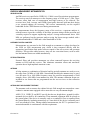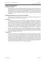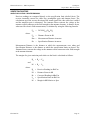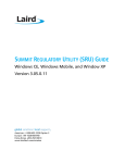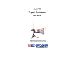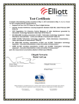
1
Test Certificate A sample of the following product received on May 11, 2011 and tested on December 21, 2011 complied with the requirements of, EN 55022:2010, "Information technology equipment – Radio disturbance characteristics – Limits and methods of measurement" (Class B) given the measurement uncertainties detailed in Elliott report R86776. Summit Data Communications Model SDC-WB40NBT _____________________ Mark E Hill Staff Engineer _______________________ Summit Data Communications _______________________ Printed Name Elliott Laboratories is accredited by the A2LA, certificate number 0214.26, to perform the test(s) listed in this report, except where noted otherwise. This report and the information contained herein represent the results of testing test articles identified and selected by the client performed to specifications and/or procedures selected by the client. National Technical Systems (NTS) makes no representations, expressed or implied, that such testing is adequate (or inadequate) to demonstrate efficiency, performance, reliability, or any other characteristic of the articles being tested, or similar products. This report should not be relied upon as an endorsement or certification by NTS of the equipment tested, nor does it represent any statement whatsoever as to its merchantability or fitness of the test article, or similar products, for a particular purpose. This report shall not be reproduced except in full Elliott Laboratories, LLC an NTS Company www.elliottlabs.com 41039 Boyce Road Fremont, CA. 94538 510-578-3500 Phone 510-440-9525 Fax EMC Test Report Class B Information Technology Equipment EN 55022:2010 Model: SDC-WB40NBT COMPANY: TEST SITE(S): REPORT DATE: FINAL TEST DATES: TOTAL NUMBER OF PAGES: PROGRAM MGR / TECHNICAL REVIEWER: ______________________________ Mark E Hill Staff Engineer Summit Data Communications 526 South Main St. Suite 805 Akron, OH 44311 Elliott Laboratories 41039 Boyce Road Fremont, CA. 94538-2435 March 14, 2012 December 21, 2011 25 QUALITY ASSURANCE DELEGATE / FINAL REPORT PREPARER: ______________________________ David Guidotti Senior Technical Writer Elliott Laboratories is accredited by the A2LA, certificate number 0214.26, to perform the test(s) listed in this report, except where noted otherwise. This report and the information contained herein represent the results of testing test articles identified and selected by the client performed to specifications and/or procedures selected by the client. National Technical Systems (NTS) makes no representations, expressed or implied, that such testing is adequate (or inadequate) to demonstrate efficiency, performance, reliability, or any other characteristic of the articles being tested, or similar products. This report should not be relied upon as an endorsement or certification by NTS of the equipment tested, nor does it represent any statement whatsoever as to its merchantability or fitness of the test article, or similar products, for a particular purpose. This report shall not be reproduced except in full File: R86776 Page 2 Elliott Laboratories -- EMC Department Test Report Report Date: March 14, 2012 REVISION HISTORY Rev# - File: R86776 Date 3-14-2012 Comments Modified By First release Page 3 Elliott Laboratories -- EMC Department Test Report Report Date: March 14, 2012 TABLE OF CONTENTS TEST CERTIFICATE ................................................................................................................................................1 TITLE PAGE ...............................................................................................................................................................2 REVISION HISTORY ................................................................................................................................................3 TABLE OF CONTENTS ............................................................................................................................................4 SCOPE ..........................................................................................................................................................................5 OBJECTIVE ................................................................................................................................................................5 STATEMENT OF COMPLIANCE ...........................................................................................................................5 DEVIATIONS FROM THE STANDARDS ..............................................................................................................5 INFORMATION TECHNOLOGY EQUIPMENT EMISSIONS TEST RESULTS ............................................6 CONDUCTED EMISSIONS (MAINS PORT) ........................................................................................................6 CONDUCTED EMISSIONS (TELECOMMUNICATIONS PORTS) ....................................................................6 RADIATED EMISSIONS ........................................................................................................................................6 MEASUREMENT UNCERTAINTIES .....................................................................................................................7 EQUIPMENT UNDER TEST (EUT) DETAILS ......................................................................................................8 GENERAL................................................................................................................................................................8 ENCLOSURE ...........................................................................................................................................................8 MODIFICATIONS ...................................................................................................................................................8 SUPPORT EQUIPMENT .........................................................................................................................................8 EUT INTERFACE PORTS ......................................................................................................................................8 EUT OPERATION ...................................................................................................................................................8 EMISSIONS TESTING ..............................................................................................................................................9 RADIATED AND CONDUCTED EMISSIONS .....................................................................................................9 RADIATED EMISSIONS CONSIDERATIONS ..................................................................................... 9 EMISSIONS MEASUREMENT INSTRUMENTATION .....................................................................................10 RECEIVER SYSTEM ............................................................................................................................................10 INSTRUMENT CONTROL COMPUTER ............................................................................................................10 FILTERS/ATTENUATORS ..................................................................................................................................10 ANTENNAS ...........................................................................................................................................................10 ANTENNA MAST AND EQUIPMENT TURNTABLE .......................................................................................10 INSTRUMENT CALIBRATION ...........................................................................................................................11 EMISSIONS TEST PROCEDURES .......................................................................................................................12 EUT AND CABLE PLACEMENT ........................................................................................................................12 RADIATED EMISSIONS (SEMI-ANECHOIC AND/OR OATS TEST ENVIRONMENT) ................................12 Preliminary Scan ...................................................................................................................................... 12 Final Maximization .................................................................................................................................. 12 SAMPLE CALCULATIONS ...................................................................................................................................13 SAMPLE CALCULATIONS - RADIATED EMISSIONS ....................................................................................13 APPENDIX A TEST EQUIPMENT CALIBRATION DATA ..............................................................................14 APPENDIX B TEST DATA .....................................................................................................................................15 APPENDIX C PRODUCT LABELING REQUIREMENTS ................................................................................22 APPENDIX D USER MANUAL REGULATORY STATEMENTS ....................................................................23 APPENDIX E BASIC AND REFERENCE STANDARDS ...................................................................................24 EN 55022:2010 .......................................................................................................................................................24 END OF REPORT ....................................................................................................................................................25 File: R86776 Page 4 Elliott Laboratories -- EMC Department Test Report Report Date: March 14, 2012 SCOPE Governments and standards organizations around the world have published requirements regarding the electromagnetic compatibility (EMC) of electronic equipment. Testing has been performed on the Summit Data Communications model SDC-WB40NBT, pursuant to the following standards. Standard EN 55022 Title Information technology equipment – Radio disturbance characteristics – Limits and methods of measurement Standard Date 2010 All measurements and evaluations have been in accordance with these specifications, test procedures, and measurement guidelines as outlined in Elliott Laboratories test procedures, and in accordance with the standards referenced therein (refer to Appendix E). OBJECTIVE The objective of Summit Data Communications is to declare conformity with the essential requirements of the EMC directive 2004/108/EC using the harmonized standard(s) referenced in this report; STATEMENT OF COMPLIANCE The tested sample of Summit Data Communications model SDC-WB40NBT complied with the requirements of: Standard/Regulation EN 55022 Equipment Type/Class Class B Standard Date 2010 The test results recorded herein are based on a single type test of the Summit Data Communications model SDC-WB40NBT and therefore apply only to the tested sample(s). The sample was selected and prepared by Ron Seide of Summit Data Communications. Maintenance of compliance is the responsibility of the company. Any modification of the product that could result in increased emissions or susceptibility should be checked to ensure compliance has been maintained (i.e., printed circuit board layout changes, different enclosure, different line filter or power supply, harnessing and/or interface cable changes, etc.). DEVIATIONS FROM THE STANDARDS No deviations were made from the published requirements listed in the scope of this report. File: R86776 Page 5 Elliott Laboratories -- EMC Department Test Report Report Date: March 14, 2012 INFORMATION TECHNOLOGY EQUIPMENT EMISSIONS TEST RESULTS The following emissions tests were performed on the Summit Data Communications model SDC-WB40NBT. The measurements were extracted from the data recorded during testing and represent the highest amplitude emissions relative to the specification limits. The complete test data is provided in the appendices of this report. CONDUCTED EMISSIONS (MAINS PORT) Testing was not performed as the EUT is a radio module and is powered directly from the host. CONDUCTED EMISSIONS (TELECOMMUNICATIONS PORTS) Testing was not performed as the EUT does not have any telecommunication ports RADIATED EMISSIONS Frequency Range Requirement Measurement Margin Status 30-230 MHz, 30 dBµV/m 22.0 dBµV/m EN 55022 Table 6 30-1000 MHz 230-1000 MHz, @264.20 -15.0 dB Complied Class B 37 dBµV/m MHz (10 m limit) Note 1 Radiated emissions testing above 1 GHz was not required because the highest frequency of the internal sources of the EUT was declared to be less than 108 MHz. File: R86776 Standard/Section Page 6 Elliott Laboratories -- EMC Department Test Report Report Date: March 14, 2012 MEASUREMENT UNCERTAINTIES ISO/IEC 17025 requires that an estimate of the measurement uncertainties associated with the emissions test results be included in the report. The measurement uncertainties given below were calculated using the approach described in CISPR 16-4-2:2003 using a coverage factor of k=2, which gives a level of confidence of approximately 95%. The levels were found to be below levels of Ucispr and therefore no adjustment of the data for measurement uncertainty is required. Measurement Type Conducted Emissions Radiated Electric Field File: R86776 Measurement Unit dBuV or dBuA dBuV/m Frequency Range 150 kHz – 30 MHz 30 – 1000 MHz 1000 – 40,000 MHz Expanded Uncertainty ± 2.2 dB ± 3.6 dB ± 6.0 dB Page 7 Elliott Laboratories -- EMC Department Test Report Report Date: March 14, 2012 EQUIPMENT UNDER TEST (EUT) DETAILS GENERAL The Summit Data Communications model SDC-WB40NBT is an 802.11abgn 1x1 with Bluetooth 2.1 module. The sample was received on May 11, 2011 and tested on December 21, 2011. The EUT consisted of the following component(s): Company Summit Data Communication Model SDCMSD40NBT Description 802.11abgn (1x1) + BT2.1 radio module Serial Number - FCC ID TWGSDCWB40NBT ENCLOSURE The EUT does not have an enclosure as it is designed to be installed within the enclosure of a host computer or system. MODIFICATIONS No modifications were made to the EUT during the time the product was at Elliott. SUPPORT EQUIPMENT The following equipment was used as local support equipment for testing: Company - Model - Description Serial Number DC Battery pack - FCC ID - No remote support equipment was used during testing. EUT INTERFACE PORTS The I/O cabling configuration during testing was as follows: Port From DC input Port 0 Port 1 To DC Battery Pack Antenna Antenna Description 2wire Single wire Single wire Cable(s) Shielded/Unshielded Unshielded Unshielded Unshielded Length(m) 1 0.2 0.2 EUT OPERATION During emissions testing the EUT was configured to transmit continuously on the noted channel and modulation. File: R86776 Page 8 Elliott Laboratories -- EMC Department Test Report Report Date: March 14, 2012 EMISSIONS TESTING RADIATED AND CONDUCTED EMISSIONS Final test measurements were taken at the Elliott Laboratories Anechoic Chamber listed below. The test sites contain separate areas for radiated and conducted emissions testing. The sites conform to the requirements of ANSI C63.4: 2003 American National Standard for Methods of Measurement of Radio-Noise Emissions from Low-Voltage Electrical and Electronic Equipment in the Range of 9 kHz to 40 GHz and CISPR 16-1-4:2007 Specification for radio disturbance and immunity measuring apparatus and methods Part 1-4: Radio disturbance and immunity measuring apparatus Ancillary equipment Radiated disturbances. They are registered with the VCCI and are on file with the FCC and Industry Canada. Site Chamber 4 Registration Numbers VCCI FCC Canada R-1684 G-57 211948 IC 2845B-4 C-1796 T-1640 Location 41039 Boyce Road Fremont, CA 94538-2435 RADIATED EMISSIONS CONSIDERATIONS Radiated emissions measurements were made with the EUT powered from a supply voltage within the expected tolerances of each nominal operating voltage/frequency for each geographical regions covered by the scope of the standards referenced in this report. File: R86776 Page 9 Elliott Laboratories -- EMC Department Test Report Report Date: March 14, 2012 EMISSIONS MEASUREMENT INSTRUMENTATION RECEIVER SYSTEM An EMI receiver as specified in CISPR 16-1-1:2006 is used for emissions measurements. The receivers used can measure over the frequency range of 9 kHz up to 7 GHz. These receivers allow both ease of measurement and high accuracy to be achieved. The receivers have Peak, Average, and CISPR (Quasi-peak) detectors built into their design so no external adapters are necessary. The receiver automatically sets the required bandwidth for the CISPR detector used during measurements. For measurements above the frequency range of the receivers, a spectrum analyzer is utilized because it provides visibility of the entire spectrum along with the precision and versatility required to support engineering analysis. Average measurements above 1000 MHz are performed on the spectrum analyzer using the linear-average method with a resolution bandwidth of 1 MHz and a video bandwidth of 10 Hz. INSTRUMENT CONTROL COMPUTER Measurements are converted to the field strength at an antenna or voltage developed at the LISN (or ISN) measurement port, which is then compared directly with the appropriate specification limit under software control of the test receivers and spectrum analyzers. This provides added accuracy since all site correction factors, such as cable loss and antenna factors are added automatically. FILTERS/ATTENUATORS External filters and precision attenuators are often connected between the receiving antenna or LISN and the receiver. This eliminates saturation effects and non-linear operation due to high-amplitude transient events. ANTENNAS A bilog antenna or combination of biconical and log periodic antennas are used to cover the range from 30 MHz to 1000 MHz. Narrowband tuned dipole antennas may be used over the entire 30 to 1000 MHz frequency range for precision measurements of field strength. Above 1000 MHz, horn antennas are used. The antenna calibration factors are included in site factors that are programmed into the test receivers or data collection software. ANTENNA MAST AND EQUIPMENT TURNTABLE The antennas used to measure the radiated electric field strength are mounted on a nonconductive antenna mast equipped with a motor drive to vary the antenna height. ANSI C63.4, CISPR 22 and KN22 specify that the test height above ground for tablemounted devices shall be 80 centimeters. Floor-mounted equipment shall be placed on the ground plane if the device is normally used on a conductive floor or separated from the ground plane by insulating material up to 12-mm thick if the device is normally used on a non-conductive floor. During radiated measurements, the EUT is positioned on a motorized turntable in conformance with this requirement. File: R86776 Page 10 Elliott Laboratories -- EMC Department Test Report Report Date: March 14, 2012 INSTRUMENT CALIBRATION All test equipment is regularly checked to ensure that performance is maintained in accordance with the company's specifications. An appendix of this report contains the list of test equipment used and calibration information. File: R86776 Page 11 Elliott Laboratories -- EMC Department Test Report Report Date: March 14, 2012 EMISSIONS TEST PROCEDURES EUT AND CABLE PLACEMENT The standards require that interconnecting cables be connected to the available ports of the unit and that the placement of the unit and the attached cables simulate the worst case orientation that can be expected from a typical installation, so far as practicable. To this end, the position of the unit and associated cabling is varied within the guidelines of ANSI C63.4, CISPR 22 and KN22, and the worst-case orientation is used for final measurements. RADIATED EMISSIONS (SEMI-ANECHOIC and/or OATS TEST ENVIRONMENT) Radiated emissions measurements in a semi-anechoic environment are performed in two phases (preliminary scan and final maximization). Preliminary Scan A preliminary scan of emissions is conducted in which all significant EUT frequencies are identified with the system in a nominal configuration. At least two scans are performed from 30 MHz up to the frequency required by the regulations specified on page 1. One or more of these are performed with the antenna polarized vertically and one or more of these are performed with the antenna polarized horizontally. During the preliminary scans, the EUT is rotated through 360°, the antenna height is varied and cable positions are varied to determine the highest emission relative to the limit. A speaker is provided in the receiver to aid in discriminating between EUT and ambient emissions if required. Other methods used during the preliminary scan for EUT emissions involve scanning with near-field magnetic loops, monitoring I/O cables with RF current clamps, and cycling power to the EUT. Final Maximization During final maximization, the highest-amplitude emissions identified in the spectral search are viewed while the EUT azimuth angle is varied from 0 to 360 degrees relative to the receiving antenna. The azimuth that results in the highest emission is then maintained while varying the antenna height from one to four meters. The result is the identification of the highest amplitude for each of the highest peaks. Each recorded level is corrected in the receiver using appropriate factors for cables, connectors, antennas, and preamplifier gain. Emissions that have values close to the specification limit may also be measured with a tuned dipole antenna to determine compliance. File: R86776 Page 12 Elliott Laboratories -- EMC Department Test Report Report Date: March 14, 2012 SAMPLE CALCULATIONS SAMPLE CALCULATIONS - RADIATED EMISSIONS Receiver readings are compared directly to the specification limit (decibel form). The receiver internally corrects for cable loss, preamplifier gain, and antenna factor. The calculations are in the reverse direction of the actual signal flow, thus cable loss is added and the amplifier gain is subtracted. The Antenna Factor converts the voltage at the antenna coaxial connector to the field strength at the antenna elements. A distance factor, when used for electric field measurements, is calculated by using the following formula: Fd = 20*LOG10 (Dm/Ds) where: Fd = Distance Factor in dB Dm = Measurement Distance in meters Ds = Specification Distance in meters Measurement Distance is the distance at which the measurements were taken and Specification Distance is the distance at which the specification limits are based. The Antenna Factor converts the voltage at the antenna coaxial connector to the field strength at the antenna elements. The margin of a given emission peak relative to the limit is calculated as follows: Rc = Rr + Fd and M = Rc - Ls where: Rr Fd Rc Ls M File: R86776 = = = = = Receiver Reading in dBuV/m Distance Factor in dB Corrected Reading in dBuV/m Specification Limit in dBuV/m Margin in dB Relative to Spec Page 13 Elliott Laboratories -- EMC Department Test Report Report Date: March 14, 2012 Appendix A Test Equipment Calibration Data Radiated Emissions, 30 - 1,000 MHz, 22-Dec-11 Description Manufacturer Rohde & Schwarz EMI Test Receiver, 20 Hz-7 GHz Sunol Sciences Biconilog, 30-3000 MHz Hewlett Packard Preamplifier, 100 kHz - 1.3 GHz File: R86776 Model ESIB7 JB3 8447D OPT 010 Asset # 1538 1548 1826 Cal Due 12/6/2012 6/24/2012 5/17/2012 Page 14 Elliott Laboratories -- EMC Department Test Report Report Date: March 14, 2012 Appendix B Test Data T83198 Pages 16 - 21 File: R86776 Page 15 EMC Test Data Client: Summit Data Communications Model: SDC-WB40 and SDC-MSD40NBT (1x1 802.11abg + BT 2.1) Contact: Ron Seide Emissions Standard(s): EN 301 489-1 V1.8.1/ FCC Part 15B Immunity Standard(s): EN 301 489-1 V1.8.1 Job Number: J78403 T-Log Number: T83198 Account Manager: Christine Krebill Class: B Environment: - EMC Test Data For The Summit Data Communications Model SDC-WB40 and SDC-MSD40NBT (1x1 802.11abg + BT 2.1) Date of Last Test: 12/16/2011 R86776 Cover Page 16 EMC Test Data Client: Summit Data Communications Model: SDC-WB40 and SDC-MSD40NBT (1x1 802.11abg + BT 2.1) Job Number: J78403 T-Log Number: T83198 Account Manager: Christine Krebill Contact: Ron Seide Standard: EN 301 489-1 V1.8.1/ FCC Part 15B Class: B Radiated Emissions (Elliott Laboratories Fremont Facility, Semi-Anechoic Chamber) Test Specific Details Objective: The objective of this test session is to perform final qualification testing of the EUT with respect to the specification listed above. Date of Test: 12/21/2011 Test Engineer: Rafael Varelas Test Location: Fremont Chamber #4 Config. Used: 3 Config Change: None EUT Voltage: 3.3Vdc General Test Configuration The EUT and any local support equipment were located on the turntable for radiated emissions testing. The test distance and extrapolation factor (if applicable) are detailed under each run description. Note, preliminary testing indicates that the emissions were maximized by orientation of the EUT and elevation of the measurement antenna. Maximized testing indicated that the emissions were maximized by orientation of the EUT, elevation of the measurement antenna, and manipulation of the EUT's interface cables. Ambient Conditions: Temperature: Rel. Humidity: 21.4 °C 35 % Summary of Results Run # Test Performed Radiated Emissions 30 - 1000 MHz, Maximized Limit Result EN55022 Class B Pass Margin 22.0dBµV/m @ 264.20MHz (-15.0dB) Modifications Made During Testing No modifications were made to the EUT during testing Deviations From The Standard No deviations were made from the requirements of the standard. R86776 RE 21-Dec-11 WB40 Page 17 EMC Test Data Client: Summit Data Communications Job Number: J78403 T-Log Number: T83198 Account Manager: Christine Krebill Model: SDC-WB40 and SDC-MSD40NBT (1x1 802.11abg + BT 2.1) Contact: Ron Seide Standard: EN 301 489-1 V1.8.1/ FCC Part 15B Run #1: Preliminary Radiated Emissions, 30 - 1000 MHz Frequency Range 30 - 1000 MHz R86776 Test Distance 5 Class: B Limit Distance 10 RE 21-Dec-11 WB40 Extrapolation Factor -6.0 Page 18 EMC Test Data Client: Summit Data Communications Job Number: J78403 T-Log Number: T83198 Account Manager: Christine Krebill Model: SDC-WB40 and SDC-MSD40NBT (1x1 802.11abg + BT 2.1) Contact: Ron Seide Standard: EN 301 489-1 V1.8.1/ FCC Part 15B Class: B Preliminary peak readings captured during pre-scan Frequency Level Pol EN55022 Class B v/h Limit Margin MHz dBμV/m 39.160 15.6 V 30.0 -14.4 52.342 14.4 V 30.0 -15.6 163.050 17.0 V 30.0 -13.0 220.169 11.8 V 30.0 -18.2 264.202 27.4 V 37.0 -9.6 398.543 23.4 H 37.0 -13.6 661.297 17.8 V 37.0 -19.2 792.591 18.8 H 37.0 -18.2 Detector Pk/QP/Avg Peak Peak Peak Peak Peak Peak Peak Peak Azimuth degrees 158 11 316 227 95 267 332 282 Height meters 1.0 2.0 1.0 1.0 2.0 2.0 1.0 2.0 Comments Preliminary quasi-peak readings (no manipulation of EUT interface cables) Frequency Level Pol Detector Azimuth EN55022 Class B v/h Limit Margin Pk/QP/Avg degrees MHz dBμV/m 52.342 -3.2 V 30.0 -33.2 QP 12 264.202 22.0 V 37.0 -15.0 QP 111 39.160 7.4 V 30.0 -22.6 QP 159 220.169 9.8 V 30.0 -20.2 QP 235 Q 398.543 3.5 H 37.0 -33.5 QP 253 792.591 19.8 H 37.0 -17.2 QP 279 163.050 0.6 V 30.0 -29.4 QP 317 661.297 7.5 V 37.0 -29.5 QP 339 Height meters 1.0 1.0 1.0 1.0 1.4 1.8 1.0 1.8 Comments random spike QP (1.00s) QP (1.00s) QP ((1.00s)) Q QP (1.00s) QP (1.00s) random spike QP (1.00s) Run #2: Maximized Readings From Run #1 Maximized quasi-peak readings (includes manipulation of EUT interface cables) Frequency MHz 264.202 792.591 220.169 39.160 661.297 398.543 R86776 Level dBμV/m 22.0 19.8 9.8 7.4 7.5 3.5 Pol v/h V H V V V H EN55022 Class B Limit Margin -15.0 37.0 37.0 -17.2 30.0 -20.2 30.0 -22.6 37.0 -29.5 37.0 -33.5 Detector Pk/QP/Avg QP QP QP QP QP QP Azimuth degrees 111 279 235 159 339 253 RE 21-Dec-11 WB40 Height meters 1.0 1.8 1.0 1.0 1.8 1.4 Comments QP (1.00s) QP (1.00s) QP (1.00s) QP (1.00s) QP (1.00s) QP (1.00s) Page 19 EMC Test Data Client: Summit Data Communications Model: SDC-WB40 and SDC-MSD40NBT (1x1 802.11abg + BT 2.1) Contact: Ron Seide Standard: EN 301 489-1 V1.8.1/ FCC Part 15B Job Number: J78403 T-Log Number: T83198 Account Manager: Christine Krebill Class: B Test Configuration Photograph #1 (Radiated Emissions) R86776 RE 21-Dec-11 WB40 Page 20 EMC Test Data Client: Summit Data Communications Model: SDC-WB40 and SDC-MSD40NBT (1x1 802.11abg + BT 2.1) Contact: Ron Seide Standard: EN 301 489-1 V1.8.1/ FCC Part 15B Job Number: J78403 T-Log Number: T83198 Account Manager: Christine Krebill Class: B Test Configuration Photograph #2 (Radiated Emissions) R86776 RE 21-Dec-11 WB40 Page 21 Elliott Laboratories -- EMC Department Test Report Report Date: March 14, 2012 Appendix C Product Labeling Requirements The following information has been provided to clarify notification, equipment labeling requirements and information that must be included in the operator's manual. These requirements may be found in the standards/regulations listed in the scope of this report. Label Location The required label(s) must be in a conspicuous location on the product, which is defined as any location readily visible to the user of the device without the use of tools. Label Attachment The label(s) must be permanently attached to the product, which is defined as attached such that it can normally be expected to remain fastened to the equipment during the equipment's expected useful life. A paper gum label will generally not meet this condition. File: R86776 Page 22 Elliott Laboratories -- EMC Department Test Report Report Date: March 14, 2012 Appendix D User Manual Regulatory Statements Where special accessories, such as shielded cables, are required in order to meet the emission limits, appropriate instructions regarding the need to use such accessories must be contained on the first page of text concerned with the installation of the device in the operator's manual. A requirement by FCC regulations, and recommended for all regulatory markets, is a cautionary statement to the end user that changes or modifications to the device not expressly approved by you, the manufacturer, could void their right to operate the equipment. File: R86776 Page 23 Elliott Laboratories -- EMC Department Test Report Report Date: March 14, 2012 Appendix E Basic and Reference Standards EN 55022:2010 EN 55022:2010 references various international and European standards to be used when making the required measurements. The references all cite dated versions of the standards, therefore the editions cited are used. International and EN equivalent standard CISPR 16-1-1 2007 +A1:2007 EN 55016-1-1 2007 +A1:2007 CISPR 16-1-2 2003 + A1 2004 EN 55016-1-2 2004 + A1 2005 CISPR 16-1-4:2007 EN 55016-1-4: 2007 CISPR 16-2-3:2003 +A1:2005 EN 55016-2-3:2004 +A1:2005 CISPR 16-4-2 2003 EN 55016-4-2 2004 Description Standard Used Specification for radio disturbance and immunity measuring apparatus and methods Part 1-1: Radio disturbance and immunity measuring apparatus - Measuring apparatus CISPR 16-1-1 2007 +A1:2007 Specification for radio disturbance and immunity measuring apparatus and methods Part 1-2: Radio disturbance and immunity measuring apparatus - Ancillary equipment - Conducted disturbances Specification for radio disturbance and immunity measuring apparatus and methods Part 1-4: Radio disturbance and immunity measuring apparatus - Ancillary equipment - Radiated disturbances Specification for radio disturbance and immunity measuring apparatus and methods - Part 2-3: Methods of measurement of disturbances and immunity – Radiated disturbance measurements CISPR 16-1-2 2003 + A1 2004 CISPR 16-1-4:2007 CISPR 16-2-3:2003 +A1:2005 Specification for radio disturbance and immunity measuring CISPR 16-4-2 2003 apparatus and methods Part 4-2: Uncertainties, statistics and limit modelling - Uncertainty in EMC measurements Unless the international publication has been modified by common modifications, indicated by (mod), either the intentional or the EN standard may be used. Where the EN standard differs from the intentional standard then the EN version is used. For all of the standards listed above there are no common modifications therefore Elliott makes use of the international version of all standards listed. File: R86776 Page 24 Elliott Laboratories -- EMC Department Test Report Report Date: March 14, 2012 End of Report This page is intentionally blank and marks the last page of this test report. File: R86776 Page 25