1
INSTRUCTION BOOK
FM 2500DD-A
GB
325 88-8514 rev. 6-437
949 601 706
Your New Appliance
Thank you for purchasing an AEG appliance.
To enable you to use your new appliance efficiently and safely, please read this
instruction book carefully before installing or using the appliance, and retain for
future reference. Should the appliance be transferred to a new owner please
ensure this instruction book is left with the appliance in order that the new owner
can get to know the functions of the appliance and the relevant warnings.
If you require further assistance or advice, please contact our Customer Care
Department either by letter or telephone:
Customer Care Department
AEG Domestic Appliances
55-77 High Street
Slough
SL1 1DZ
Tel: 08705 350350*
* calls to this number may be recorded for training purposes
2
Contents
Page No.
For the user
Your New Appliance ........................................................................................
Safety information ..........................................................................................
Product description ........................................................................................
Downdraught Extractor ..........................................................................
Height positions ....................................................................................
Extraction rates ......................................................................................
Electronic control system ......................................................................
How to use it ....................................................................................................
Downdraught Extractor ..........................................................................
Finger touch ..........................................................................................
Downdraught Extractor ..........................................................................
Extraction rates ......................................................................................
Intensive extraction ................................................................................
Timer-controlled switching off ..............................................................
Autostop ................................................................................................
Correct ventilation ..................................................................................
Cleaning and maintenance ............................................................................
Aluminium ............................................................................................
Ceramic hob ..........................................................................................
Top cabinet ..............................................................................................
Extraction shaft ......................................................................................
What to do if ....................................................................................................
Service and spare parts ..........................................................................
3
2
5
7
8
8
8
8
9
9
9
10
13
14
15
16
17
18
18
18
18
19
31
33
Contents
Page No.
For the electrician
Unpacking ......................................................................................................
Technical data ................................................................................................
Installation........................................................................................................
Mounting ........................................................................................................
20
21
22
26
How to read the operating instructions
1... 2...Step by step
Hints and tips
Safety information
Environmental information
The products are continuously being developed and it may occur that some product specifications
are changed after this instruction book was printed. We therefore have to make reservation for any
changes or printing errors.
4
Safety Information
Cleaning and Maintenance
This downdraught extractor is
designed for use in a normal domestic household. If used in any other
way there could be a risk of an accident.
For hygiene and safety reasons the
downdraught extractor must be kept
clean. In a worst case scenario, a
clogged fat filter can ignite and burst
into flames.
Children
Keep an eye on children when the
downdraught extractor is in use.
Never let children touch or play with
the control knobs.
Service
Service and repair must be performed by our service organisation
or an organisation approved by us.
Only spare parts supplied by our
service organisation may be used.
Use
Never leave the downdraught extractor unattended when deep-frying or
melting fat, paraffin wax or other
easily ignited substances. Do not
flambe in the immediate proximity
of a downdraught extractor that is
switched on. It can cause a fire. In
the event of fire, the downdraught
extractor must be switched off.
Unpacking
Make sure the packaging is disposed
of in such a manner that children
cannot access the used packaging.
Put out the fire with a lid. Never
use water.
Check that the downdraught extractor is turned off when not in use.
5
Installation
The downdraught extractor may only
be installed by an authorised electrician or someone approved by the
manufacturer.
Work carried out by unqualified persons can lead to personal injury
and/or damage to property and may
damage the downdraught extractor.
During installation make sure the
electricity cable is not pinched.
Do not interfere with the downdraught extractor electrical parts.
Extracted air must not be connected
to a duct that is already used to discharge flue gases from an oil-fired
boiler or similar.
Disposal
Help to avoid accidents when throwing out the downdraught extractor.
Remove the electricity cable from
the wall socket and cut it off close to
the downdraught extractor.
6
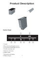
Product Description
Control Panel
8
7
3
2
5
4
1. On/off
2. Raise the downdraught extractor
3. Lower the downdraught extractor
4. Set the extraction rate
5. Intensive extraction
6. Minute timer
7. Extraction rate display
8. Minute display
7
6
1
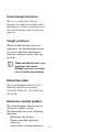
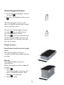
Downdraught Extractor
The air is sucked in at the air
dampers through the fat filter and is
then blown via the extraction hose to
the extraction duct and out into the
open air.
Height positions
When installed beside electrical
appliances, the downdraught extractor can be adjusted continuously
from the centre position to the top
position.
When installed beside a gas
appliance, the downdraught extractor can only
extract in the top position.
Extraction rates
The downdraught extractor has 4
different extraction strengths:
150m3/h, 220m3/h, 345 m3/h and
480 m3/h.
Electronic control system
The downdraught extractor has an
electronic control system.
The electronics have the following
functions:
- Extraction rate display
- Timer-controlled operation
- Autostop
- Grease filter cleaning indicator
8
How to use
Downdraught Extractor
Never leave the downdraught extractor unattended
when deep-frying or melting
fat or other easily ignited
substances. Do not flambe
food in the immediate proximity of a downdraught
extractor that is switched on.
This can cause fire.
In the event of fire, the
downdraught extractor must
be switched off.
Put out the fire with a lid.
Never use water.
Finger Touch
The buttons have to be touched for
at least 1 second before they are
activated.
If the buttons are touched for more
than 10 seconds, the downdraught
extractor will be switched off automatically. If two buttons are touched
at the same time, neither of the settings is registered, apart from resetting the indicator for cleaning the fat
filter.
The downdraught extractor can
always be switched off by pressing
the
button.
k
9
Downdraught Extractor
1. To turn the downdraught extractor
on, press
.
2. To select the height position, press
.
k
m
The downdraught extractor will
move to middle position and switch
on at extraction rate 1.
To turn the downdraught extractor
off, hold
down until bottom
position has been reached.
Pressing
will turn extraction off,
but the downdraught extractor will
remain where it is and not descend
into the worktop.
l
k
Height positions
Installation beside electrical appliances
The downdraught extractor is
variable between the middle and top
position.
Raising
The downdraught extractor is
switched on.
Select the height position within 10
seconds.
1. Press
.
The downdraught extractor will
move to middle position. The
dampers are deployed.
2. Press
again.
m
m
10
The downdraught extractor will then
stop rising automatically when the
button is released or when top position is reached.
Safety
If the downdraught extractor is
obstructed when raising, it will
switch off automatically.
Lowering
1. Press
l.
l
, the downIf you keep pressing
draught extractor will move steplessly between the top and bottom position. It will stop when you release
the button.
When the middle position is reached,
the dampers retract and extraction is
turned off.
Installation beside gas appliances
The downdraught extractor can only
extract in top position.
11
Raising
When the downdraught extractor is
switched on.
Select the height position within 10
seconds.
1. Press
.
The downdraught extractor will
move to top position and switch on
at extraction rate 1. The dampers
will deploy on the way up.
m
Safety
If the downdraught extractor is
obstructed on the way up, it will
switch off automatically.
Lowering
1. Press
l.
Extraction will be turned off. The
downdraught extractor will stop
when you release the button.
k
Pressing
will turn extraction off,
but the downdraught extractor will
remain where it is and not descend
into the worktop.
12
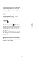
Extraction rates
The downdraught extractor can be
set to three levels and intensive
extraction.
Level 1: 150 m³/h
Level 2: 220 m³/h
Level 3: 345 m³/h
Intensive extraction: 480 m³/h
Setting the extraction rate
When the downdraught extractor is
on, raised and at rate 1.
<
1. Press
one press = level 2
two presses = level 3
Adjusting the extraction rate
The extraction rate can be adjusted
by pressing
.
<
Switching extraction off
Press
until the display shows 0.
<
13
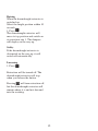
Intensive extraction
The downdraught extractor is on and
raised.
1. Press
b.
The downdraught extractor will
extract on intensive for 5 minutes. It
will then return automatically to its
last setting before intensive extraction was activated. If extraction was
off before intensive extraction was
activated, extraction will be turned
off automatically after 5 minutes.
Switching off intensive extraction
You can switch intensive extraction
off before the 5 minutes are up.
Press
b.
14
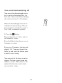
Time-controlled switching off
You can set the downdraught extractor to switch off automatically at a
later time. Time-controlled switching
off can be set from 1 to 99 minutes.
When the downdraught extractor is
switched on and raised up. The suction strength is switched to speed 1,
2 or 3 (not to intensive suction).
1. Press the
A button.
By pressing once at a time, you set
one minute at a time.
If you hold the button down, you set
5 minutes at a time.
If you pass 99 minutes, the time will
display “00”. You must then let the
button go and press the button again
to make a new setting.
You can read off the time set in the
display. The time counts down one
minute at a time. When there is one
minute left, the time counts down
one second at a time.
15
When the time set has passed, suction strength is switched off. The
downdraught extractor remains in
the height position set.
If you want to switch off the extraction rate before the time has passed,
press the
button until the display
shows “00”.
A
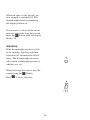
Autostop
If the downdraught extractor is left
on by mistake, Autostop will turn
extraction off automatically after 6
hours. The downdraught extractor
will remain at the height position to
which it was set.
When Autostop has been active, the
control lamp for
flashes.
Press
k
k
to reset Autostop.
16
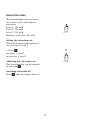
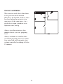
Correct ventilation
The extractor works best when there
is low pressure in the kitchen.
Therefore, the kitchen windows must
be closed when the extractor is in
operation. At the same time, it is a
good idea to open a window in an
adjacent room; see fig.
Always start the extractor a few
minutes before you start preparing
food.
Always continue to ventilate after
you finish preparing food. Use intensive extraction with automatic stop
or time-controlled switching off after
15 minutes.
17
Cleaning and maintenance
Top cabinet
The product should be kept
clean for reasons of hygiene
and safety.
The top cabinet may become spattered with fat from frying.
Never use metal cleaning
pads, metal sponges, hard
plastic sponges, scouring
powder, soft soap or other
abrasive and caustic cleaners.
To clean
1. Switch the extractor on and raise
it to the top position.
2. Lift the top cabinet off.
3. Wipe the top cabinet with a damp
cloth and washing-up liquid or
universal cleaner.
Filter
After 30 hours of use the timer display will indicate that the filter
needs cleaning. "CL" will appear on
the display.
Aluminium
Carry out daily cleaning with a well
wrung-out cloth. For more stubborn
soiling, use a cloth or a soft plastic
sponge together with washing-up
liquid or all-purpose cleaner.
1. Switch the extractor on and raise
it to top position.
2. Lift the top cabinet off.
3. Turn the top cabinet upside down
and put it on a soft base. Take
care not to scratch the glass on
the top.
4. Remove the spring securing the
filter by pressing on its sides.
5. Lift the filter out.
6. Wash the filter in hot water and
washing-up liquid or in the dishwasher. The filter may become
discoloured if cleaned in the dishwasher. This will not impair its
effectiveness.
Never use metal cleaning pads,
metal wool, hard plastic sponges,
scouring powder, soft soap or other
abrasive or caustic cleaning agents.
Ceramic hob
After use, wipe the extractor with a
damp cloth and washing-up liquid. If
necessary, finish off with a clean,
dry cloth.
18
7. Assemble the filter, spring and
top cabinet in reverse order. The
filter must be completely dry
before it is re-fitted in the extractor.
8. Reset the filter cleaning indicator
by pressing
and
simultaneously for 3 seconds. "CL" will
disappear from the display. If you
clean the filter before the tablemounted cooker hood has been in
use for 30 hours ("CL" has not
appeared on the display), the filter cleaning indicator can be reset
in the same way.
<
A
If there is a power cut, the filter indicator will be reset automatically.
Extraction shaft
Wipe the extraction shaft with a
damp cloth and washing-up liquid or
universal cleaner.
19
Unpacking
Check that the appliance has no
faults and is undamaged on delivery.
Transport Damages
Any damages resulting from a transport which you have not performed
yourself must be communicated to
the dealer within one week of receipt
of the product.
On the rating plate which is placed
on the back of the product you will
find the CE marking and the product’s serial number. Write the serial
number on the front of present
instruction book so it is easily accessible in the event of service.
Removal of Packaging
All packaging can be recycled.
Contact your local authority if you
do not know where to dispose of the
packaging.
20
Technical Data
Model FM 2500DD-a:
Product dimensions:
Width:
Depth:
Height:
180 mm
520 mm
600 mm
Installation dimensions:
Width:
Depth:
Height:
160 mm
490 mm
647 mm
Extraction rate:
Level 1
Level 2
Level 3
Intensive extraction
Extraction rate:
Total output:
Exhaust connection:
Round pipe or hose:
150 m³/h
220 m³/h
345 m³/h
480 m³/h
310 W
Ø 120 mm
21
Installation
Electrical Installation
Installation must be carried
out by an authorised electrician or by a person authorised by the manufacturer.
Work carried out by unqualified persons can lead to personal injury and/or damage
to property and may spoil
thedowndraught extractor.
During installation make
sure the cable is not
pinched. Do not interfere
with the electrical components of the downdraught
extractor. The exhaust air
must not be connected to a
duct that is already used to
carry flue gasses away from
an oil-fired boiler or similar
appliances. The exhaust hose
must not be connected to a
chimney or the like that is
used to carry flue gasses
away from a boiler, woodburning stove, fireplace, etc.
22
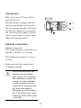
Connection
Min. cable size: 0.75 mm² Cable
type: HO5VV-F
Installation must comply with any
special requirements laid down by
the local energy provider. The product must be connected via an external switch that disconnects all poles
with a contact gap of at least 3 mm.
(May be the main switch).
L
L2
L1
N
PE
Exhaust connection
Exhaust connection:
The connecting piece for the hose or
pipe has a diameter of 120 mm.
The exhaust hose must be at least 1
m long.
Make sure that the connection is
completely airtight.
The cooker hood must be
connected to an exhaust
hose or pipe. It is vital that
this connection is made for
reasons of safety, and the
cooker hood must not be
connected to the power supply before the exhaust
hose/pipe has been connected. If the outlet is in a wall,
it must be fitted with a grille
or the like.
23
N
Installation beside a gas
appliance
If the downdraught extractor is
installed beside a gas appliance, it
must only be operated in top position and extract from the other side,
i.e. the damper closest to the gas
appliance must be closed permanently.
This can be done as follows:
1. Modifying the electronic control
system
On the PCB cut the jumper labelled
"JP01". The downdraught extractor
can now only be operated in top
position.
2. Removing a damper
To be able to mount the cover plate,
the damper has to be removed as follows:
1. Switch the downdraught extractor
on and raise it to top position.
2. Lift the top cabinet off.
3. Turn the top cabinet upside down
and put it on a soft base. Take
care not to scratch the glass on
the top.
4. Remove the two screws holding
the damper and the single screw
holding the activation arm that
closes the damper.
The damper can now be removed.
24
3. Fitting the cover plate
Fit the cover plate as follows:
1. Position the cover plate against the glass on the top cabinet.
2. Position the cover plate against the top cabinet.
3. Mark the four holes on the top cabinet, using the cover plate as a template.
4. Remove the cover plate and drill the four marked holes with a 3.2mm drill.
5. Take the backing off the tape.
6. Lay the cover plate against the top cabinet and press firmly into place.
7. Fix the plate through the four holes with the supplied blind rivets.
The downdraught extractor must not be used beside a gas unit if air
recirculation is chosen for the kitchen.
25
Mounting
The unit may be mounted in any
type of kitchen worktop with a
thickness of 28 to 40 mm.
Position
It is advisable to position the downdraught extractor immediately next
to the hob. If two or more hobs are
being used, the downdraught extractor should be positioned between
them so that optimum use can be
made of its variable extraction direction.
26
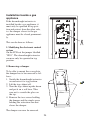
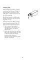
Cutting Out
When fitting this product: read the
instructions on this page. When fitting this unit in conjunction with
other units: read the instructions on
the following page.
For fitting this unit you will need a
Phillips screwdriver and the fixing
supplied (see fig.).
Distance from wall: Min. 150 mm
from flammable material Min. 50
mm from non-flammable material.
1. Saw a hole of the specified
dimensions in the worktop, see
“Technical data, installation
dimensions”.
2. Insert the unit in the hole and use
the fixing supplied in the slot that
is the best fit for the kitchen
worktop or the thickness
involved. Secure the fixing with a
manual screwdriver.
27
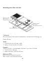
Mounting more than one hob
Distance to wall:
Min. 150 mm
(flammable material)
Distance to wall:
Min. 50 mm
(non-flammable material)
m
0m
49
Reinforcement beam
Cutting out
The measurement of the selected combination is calculated in the following way:
Depth: 490 mm
Width:
1. Calculate the sum of all units’ width.
2. Subtract 20 mm from the total width.
Example:
A hob of 720 mm + a downdraught of 180 mm + a gas hob of 360 mm.
1. 720+180+360= 1260 mm
2. Width of the hole: 1260-20=1240 mm
Distance to Wall:
Min. 150 mm to flammable material.
Min. 50 mm to non-flammable material
28
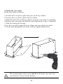
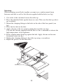
Mounting:
When mounting several hobs together you must use a reinforcement beam
between each hob as well as the silicone supplied with the hobs (see fig.)
1. Cut a hole of the calculated size in the table top
2. Place the individual hobs upside down on a mat. Take care that the top side is
not scratched.
3. Mount the clamping fittings in the holes in the side of the base panels (see
fig.)
4. Place the first hob in the hole.
5. Apply silicone to the two corners joining the next hob (see fig.)
Use only the silicone supplied with the hobs as this is intended to tolerate the
high temperatures of the appliance.
6. Push a reinforcement beam up against the hob. Apply silicone on the reinforcement beam (see fig.)
7. Tighten the clamping fittings to the table top using a screwdriver.
8. Repeat the process for the other hobs.
Silikonet
29
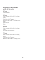
Overview of the outside
width of the units
180 mm
Downdraught
360 mm
Glass ceramic hob with 2 cooking
zones
Gas hob with 2 burners
Induction hob with 2 cooking zones
Grill
Grill / Fryer
Wok
580 mm
Glass ceramic hob with 4 cooking
zones
Gas hob with 4 burners
720 mm
Glass ceramic hob with 4 cooking
zones
Gas hob with 4 burners
Induction hob with 4 cooking zones
30
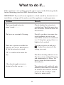
What to do if...
If the appliance is not working correctly, please carry out the following checks
before contacting your local AEG Service Force Centre.
IMPORTANT: If you call out an engineer to a fault caused by incorrect use or
installation, a charge will be made even if the appliance is under guarantee.
Problems
Remedy
The downdraught extractor
doesn’t work.............
Check whether the extractor is
switched on. Check the main fuse
has not failed. Check the fuses for
the extractor.
The fuses are constantly blowing..
Possibly, you have too many electrical appliances in use at one
time. If the extractor is connected
to a 13 Amp fuse group, there is a
high risk of overload.
There was a power cut while the
extractor was in use. Extraction is
off but the extractor is raised.
Turn the extractor on and press
. Adjust the extractor to the
setting you want.
k
“CL” is visible on the timer display.
The filter cleaning indicator is on.
See the section entitled “Cleaning
and maintenance of...Filter” for
how to clean the filter and reset
the indicator.
If the downdraught extractor is
obstructed on the way up...........
The extractor will switch off automatically and cannot be activated.
To activate the extractor, turn the
power off and reconnect at the
contact or main switch.
31
In-guarantee customers should ensure that the above checks have been made as
the engineer will make a charge if the fault is not a mecanicas or electrical
brakedown.
Please note that it will be necessary to provide proof of purchase for any
in-guarantee service calls.
32
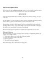
Service and Spare Parts
In the event of your appliance requiring service, or if you wish to purchase spare
parts, contact your local AEG Service Force Centre by telephoning:
08705 929 929
Your call will automatically be routed to the Service Centre covering your post
code area.
For the address of your local Service Force Centre and further information about
Service Force, please visit the website at www.serviceforce.co.uk
In-guarantee customers should ensure that the recommended checks under the
heading “What to do if..” have been made as the engineer will make a charge if
the fault is not a mechanical or electrical breakdown.
Please note that proof of purchase is required for in-guarantee service calls.
Help us to help you
Please determine your type of enquiry before writing or telephoning. When you
contact us we need to know:
1. Your name, address, post code and telephone number
2. Clear and concise details of the fault.
3. Date of purchase
4. The model and serial number
This information can be found on the rating plate.
33
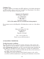
Customer Care
For general enquires concerning your AEG appliance or for further information
on AEG products, please contact our Customer Care Department at the address
below or visit our website at www.aeg.co.uk
Customer Care Department
AEG Domestic Appliances
55-77 High Street
Slough, Berkshire
SL1 1DZ
Tel 08705 350350*
*calls to this number may be recorded for training purposes
For customer service in the Republic of Ireland please contact us at the address
below:
AEG
Electrolux Group ( Irl ) Ltd
Long Mile Road
Dublin 12
Republic of Ireland
Tel: + 353 (0) 4090 754
Email: [email protected]
GUARANTEE CONDITIONS
Standard guarantee conditions
We, AEG, undertake that if within 12 months of the date of the purchase this
AEG appliance or any part thereof is proved to be defective by reason only of
faulty workmanship or materials, we will, at our discretion repair or replace the
same FREE OF CHARGE for labour, materials or carriage on condition that:
· The appliance has been correctly installed and used only on the electricity or
gas supply stated on the rating plate.
· The appliance has been used for normal domestic purposes only, and in
accordance with the manufacturer’s operating and maintenance instructions.
34
·
·
·
·
The appliance has not been serviced, maintained, repaired, taken apart or
tampered with by any person not authorised by us.
All service work under this guarantee must be undertaken by a Service Force
Centre. Any appliance or defective part replaced shall become the
Company’s property.
This guarantee is in addition to your statutory and other legal rights.
Home visits are made between 8.30am and 5.30pm Monday to Friday. Visits
may be available outside these hours in which case a premium will be
charged.
Exclusions
This guarantee does not cover:
· Damage or calls resulting from transportation, improper use or neglect, the
replacement of any light bulbs or removable parts of glass or plastic.
· Costs incurred for calls to put right an appliance which is improperly
installed or calls to appliances outside the United Kingdom.
· Appliances found to be in use within a commercial environment, plus those
which are subject to rental agreements.
· Products of AEG manufacture which are not marketed by AEG.
European Guarantee
If you should move to another country within Europe then your guarantee moves
with you to your new home subject to the following qualifications:
· The guarantee starts from the date you first purchased your product.
· The guarantee is for the same period and to the same extent for labour and
parts as exists in the new country of use for this brand or range of products.
· This guarantee relates to you and cannot be transferred to another user.
· Your new home is within the European Community (EC) or European Free
Trade Area.
· The product is installed and used in accordance with our instructions and is
only used domestically, i.e. a normal household.
· The product is installed taking into account regulations in your new country.
Before you move please contact your nearest Customer Care centre, listed below,
to give them details of your new home. They will then ensure that the local
Service Organisation is aware of your move and able to look after you and your
appliances.
35
France
Germany
Italy
Sweden
UK
Senlis
Nürnberg
Pordenone
Stockholm
Slough
+33 (0)3 44 62 29 29
+49 (0)800 234 7378
+39 (0)800 117511
+46 (0)8 672 53 60
+44 (0)1753 219899
36
37
38
39
40