1
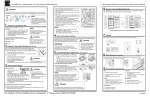
ECE 2036 First Mbed C/C++ Assignment
Due Date: Friday, September 14
Introduction to Embedded Devices and a Thermostat Example Product
Embedded devices account for 98% of the world’s microprocessors. For every desktop computer, there
are over 100 embedded devices. A high-end car can contain up to 100 microprocessors. Embedded
devices contain a computer with software that is typically not changed by the user (called Firmware).
Most users are not aware that their cellphones, cameras, audio players, and TVs contain a computer
with firmware. C/C++ is currently the most widely used language for embedded devices. ARM
processors similar to the one found in the mbed module are used in about 80% of embedded devices
including most cellphones.
Real-Time Systems
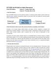
Many embedded devices are also real time systems. A real-time system needs to read in data from
external sensors, perform computations based on new sensor data, and update the control outputs
within a fixed period of time.
A Real-Time System reads in sensor data, processes the data, and updates control outputs
Examples in cars include airbags, antilock brakes, and engine controls. Autopilots in airplanes and
spacecraft are another example. In many of these systems, responding too slowly will cause system
failure. Most real-time systems need a response time on the order of milliseconds or even
microseconds.
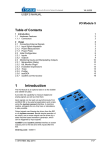
The new Nest Thermostat
Programmable home heating and cooling thermostats are also embedded devices. Thermostats could
perhaps also be considered a real-time system, but with a response in the minutes range that is several
orders of magnitude slower than most applications. The new nest thermostat seen on the next page was
designed by an engineer that previously designed Apple’s iPods. It uses a color LCD similar to those in
cellphones and a rotating ring for user input. Menus are used to change settings and display data. This
device is now available at your neighborhood Lowes, the Apple Store, and Amazon. Nest Labs is one of
Silicon Valley’s newest startup success stories. It is an interesting example of how even common
household devices are currently being re-engineered using new technology.
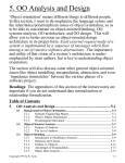
The Nest thermostat
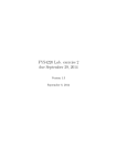
As seen in the printed circuit board (PCB) image below, the nest contains an ARM Cortex A8 32-bit
processor, temperature, light, motion, and humidity sensors and Wi Fi. The motion sensor senses when
no one is home to save energy. A learning algorithm monitors your inputs to setup automatic
scheduling. Wi Fi can be used for remote control via the web and for automatic firmware updates.
Hardware found in the Nest
Most home heating systems use 24V AC relays to turn the fan, heater, and cooling on and off. A driver
circuit converts a digital logic output signal from the processor to the higher voltage and current levels
required to trigger the relays.
Building a Thermostat using mbed
For this assignment, we will use the ARM processor on the mbed module and develop C/C++ code to
build a basic thermostat. Mbed’s I/O devices all have been setup with easy to use C++ Application
Programming Interface (API) calls that are described in the mbed handbook. The API code provided with
mbed uses C++ classes and methods to make them easier to use. These are similar to a simple device
driver and it is not necessary to understand the hardware details of each I/O device to develop complex
C/C++ applications on mbed. Follow the hyperlinks provided in this document for additional
documentation and C/C++ code examples.
An LM61 analog temperature sensor will be used to read the temperature. Using mbed’s built in analog
to digital convertor and a C/C++ I/O Application Programming Interface (API) call, the voltage from the
sensor will be converted from analog to a floating point value returned in a C/C++ variable. This
temperature value is then checked to determine when to turn on and off the heating and cooling
systems. Two of mbed’s built in LEDs will be used to indicate the value of the output signals that control
the heating (LED4) and cooling (LED3). It will not be attached to an actual HVAC system or require a
driver circuit to control the relays.
Thermostats and control systems must use hysteresis to avoid rapidly switching on and off. Mechanical
systems take time to respond and wear out faster if they are constantly turned on and off. They need to
run for a longer period of time to avoid excessive mechanical wear. They are also more energy efficient
with longer run times. In the case of a thermostat for a heater, with hysteresis the heater would turn on
at the temperature control point, but then not turn off until the temperature has increased a couple
degrees. It would not turn back on until the temperature drops a couple degrees. This requires state
information (i.e. heater is on or off) and then checking a different temperature threshold when turning
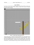
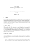
the device on versus turning it off. The figure below shows a simple state transition diagram for a
thermostat set at 75. The plus and minus 1s provide the hysteresis. It should start in the state where the
heater is off.
Temp<(75-1)
Heat
Heat
Off
On
Temp>(75+1)
State Diagram for a Thermostat set to 75
Modeling a State Machine in C/C++
Nested control structures are required to implement a complex state machine in software. As an
example, a simple state machine is shown below in C/C++ that blinks an LED. When the program runs,
LED1 changes every .3 seconds.
include "mbed.h"
DigitalOut myled(LED1);
int main()
{
enum Statetype { LED_off = 0, LED_on };
Statetype state = LED_off;
while(1) {
switch (state) {
case LED_off:
myled = 0;
state = LED_on;
break;
case LED_on:
myled = 1;
state = LED_off;
break;
}
wait(0.3);
}
}
A simple state machine in C/C++ that blinks an LED
An infinite while loop containing a switch() statement helps structure the code. The switch() statement
selects one of several cases based on the current state. Each case (i.e., state) then checks the
appropriate conditions to assign the next state. An enumerated type is used for state. Use this overall
structure in your code for the thermostat’s state machine. It will be more structured, readable, and
easier to understand. For just two unconditional states, an if..else statement could be used, but with a
case statement adding more states and input conditions will be easier as the state machine gets more
complex. A default case could be added to jump to the initial state just in case it ever entered an
undefined state.
Reading the Temperature Sensor
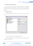
An LM61 wiki page is provided that shows how to connect the LM61 sensor and read the temperature
using C/C++ on the mbed module. Start by wiring up the LM61 sensor to mbed and getting the demo
code at the wiki page to work as shown. Use the compiler import code link (i.e., box after source code)
on the LM61 wiki page to copy over the complete project demo files for the LM61. This will verify your
hardware connections before trying your new code. See the breadboard theory wiki, if you have not
used a breadboard before and be very careful whenever inserting or removing the mbed module, as
the pins can easily bend and break. If that happens, you will need a new mbed module. It is a good idea
to put the mbed on your breadboard once and leave it there. A larger version of the LM61 breadboard
setup photograph is also available using the link under the image on the LM61 wiki page. You will need
to follow the instructions provided in your mbed box to setup a user account for access to the C/C++
compiler and space to save source files, if you have not already done so.
The sensor outputs a voltage that indicates the current temperature. An Analog to digital convertor
inside the processor converts the analog voltage input to a 12-bit integer value at a maximum sample
rate of 200Khz. The mbed C++ API AnalogIN reads a 3.3V max analog input and scales it to a float value
between 0 and 1.0 (i.e., a 1.0 would be 3.3V and 0 would be 0V). DigitalOut can be used to control the
LEDs. Use LED4 to indicate the state of the heater (i.e., LED4 on means the heater is on).
The mbed I/O APIs use C/C++ classes to enable users to work at a higher level of abstraction without
dealing with the low-level hardware details. As example, here is what happens automatically when you
use the AnalogIn API C++ class to read an analog input pin:
1. The pin is configured for analog input on initial use of AnalogIn. Most I/O pins can have one of
several different functions that are controlled by registers. I/O registers on RISC processors are
in memory addresses in a special range reserved just for I/O devices . Pins are a critical resource
on an IC, so most I/O pins are configurable on new ICs. A pin can cost as much as 100K
transistors inside the chip.
2. Whenever the AnalogIn variable is read, the eight input analog multiplexor is set to select the
correct analog channel to read the pin. This requires writing a value to another I/O control
register along with a small delay for the analog voltage to stabilize.
3. The A/D convertor is then started by writing a start A/D conversion bit in the A/D control
register.
4. The software then waits in a while loop for the A/D to report back that the conversion is
complete. The hardware sets a bit in an A/D status register when this happens. The A/D can only
read 200K samples per second. This is a lot slower than instruction execution times, so code
needs to wait for the A/D conversion complete bit.
5. The AnalogIn value is then read in from the A/D data register, scaled from 0.0 to 1.0, and
returned as the float value of the AnalogIn variable.
A lot of development time is saved by using AnalogIn, there is no need to find and understand all of
these hardware details in the LPC1768 User’s Manual to get the I/O device to work. This is why I/O
device drivers are typically used in larger systems.
Since temperature changes slowly, it is engineering overkill to check the temperature as fast as possible
in a tight while loop. In an actual system, running slower can save power or provide extra CPU time for
other tasks. On mbed, a time delay can be added using wait(). Check the temperature no more than
twice a second.
Printf() can be used to display data using the USB cable on a terminal application window running on a
PC. In Windows, you need to install a USB virtual com port driver with your mbed attached before using
printf() the first time. This driver is only used for printf() and not to download code. The driver needs to
be re-installed, if you switch to another mbed as it locks to each mbed’s unique serial number. Printf() is
a handy way to display additional data to debug your program. Spare LEDs can also be used to output a
couple values as a debugging aid.
With the temperature sensor connected and the program running, you can simulate the effect of the
heater turned on by pushing down on the sensor with your finger (being careful not to knock it loose
from the protoboard). Your finger is typically a bit cooler than your core body temperature and it does
not cover the entire sensor, but you should be able to warm the sensor up to the high 80s after a few
seconds. So you can test the thermostat by setting the control point a bit higher than room temperature
so that the heat comes on (LED4). Then by warming it up a couple degrees with your finger you should
see the heat turn off after a couple seconds. Monitor the temperature using printf()s while this is
happening. It is also possible to cool down the sensor using an ice cube in a small plastic bag (be careful
not to get water on the breadboard or sensor leads). By spraying it with an aerosol can of dust off
cleaner, it can be even be cooled below freezing.
The basic heater thermostat counts 70% (out of 100%). Demonstrate the thermostat to the TAs for
checkoff using the checkoff sheet provided. It is possible to demo each part or you can wait until all
parts are working. Turn in the checkoff sheet after getting the last signoff, so that the TA can record your
grade.
Further Enhancements
Add Cooling (additional 10%) Build a thermostat that controls heating (use LED4) and cooling (use LED3)
at the same time (with two different temperature thresholds (i.e., a heat and a cool setting) and three
states (off, heat, cool). The heat temperature setting should always be several degrees lower than the
cooling setting. The cooling system also needs a couple degrees of hysteresis. Use printf()s in addition to
the two LEDs to output status and temperature. It might be helpful to draw a new state diagram first.
Add Sensor Data Logging (additional 10%) Once every 10 seconds, write the temperature, thermostat
state, time and date to a file. An example showing local file I/O is in the handbook. The mbed has 2MB
of file storage. It is also used to store your code, so be careful not to fill it up or erase the file system.
Write out two minutes of data and stop (if you leave a file open and the program continues to write to it
you might need to reset the file system on mbed by holding the reset switch down, so use LED1 to show
when it is done logging two minutes of data). For time and date, mbed has a real-time clock calendar
that is supported by C/C++ time functions. The date and time will power up to a default value, but it can
be set using a time function API. The file system can be viewed on your PC just like any USB flash drive,
so after the program runs view the datalog.txt file using the PC. You can also delete it from the PC. It is
best not to leave the file system open while waiting, since if power is lost the directory or files may be in
a strange state, so the file is closed each time a line is written before the time delay and then opened
again for write with append (i.e., “a”). Here is a C/C++ example that logs a line with “Hello File World”
very 10 seconds to a file along with the number of seconds from the real time clock:
#include "mbed.h"
LocalFileSystem local("local");
// Create the local filesystem under the name "local"
DigitalOut myled(LED1);
int main()
{
for(int i=0; i<5; i++) {
FILE *fp = fopen("/local/datalog.txt", "a");
// Open "datalog.txt" on file system for writing with append
fprintf(fp, "Hello File World! ");
time_t seconds = time(NULL);
fprintf(fp," %d seconds running \n\r", seconds);
fclose(fp);
wait(10);
}
myled = 1;
}
Local File System I/O and Time Example
The thermostat feature must still be operational while data logging is turned on.
Add User Input (additional 10%) Use two pushbuttons to change the temperature setting for the heater.
One pushbutton to increase and the other to decrease a degree each time it is hit. See the pushbutton
wiki page for additional help using pushbuttons with mbed. Use a printf() to output the temperature
setting each time it changes. Small pushbuttons are available for use on your breadboard.
Additional Sensor and I/O Devices
For those that want to try additional projects with mbed on their own, most new ICs come in small
surface mount packages that will not directly plug into a student breadboard. Devices similar to those
used in the nest are available on small breakout boards that will plug directly into a breadboard for use
with mbed. A large assortment of devices is available using this table of additional sensor ICs, LCD
displays, and networking hardware. Many have code examples in the mbed cookbook.