1
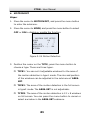
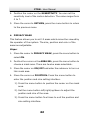
C7DN User Manual Day Night Box Camera· User Manual Thank you for purchasing our product. If there are any questions, or requests, please do not hesitate to contact the dealer. This manual applies to following cameras: Model C7DN This manual may contain several technical incorrect places or printing errors, and the content is subject to change without notice. The updates will be added to the new version of this manual. We will readily improve or update the products or procedures described in the manual. 2 Day Night Box Camera· User Manual DISCLAIM ER STATEMENT “Underwriters Laboratories Inc. (“UL”) has not tested the performance or reliability of the security or signaling aspects of this product. UL has only tested for fire, shock or casualty hazards as outlined in UL’s Standard(s) for Safety, UL60950-1. UL Certification does not cover the performance or reliability of the security or signaling aspects of this product. UL MAKES NO REPRESENTATIONS, WARRANTIES OR CERTIF ICATIONS WHATSOEVER REGARDING THE PERFORMANCE OR RELIABILITY OF ANY SECURITY OR SIGNALING RELATED FUNCTIONS OF THIS PRODUCT.” 3 Day Night Box Camera· User Manual Regulatory Information FCC Information FCC compliance: This equipment has been tested and found to comply with the lim its for a digital device, pursuant to part 15 of the FCC Rules. These limits are designed to provide reasonable protection against harmful interference when the equipment is operated in a commercial environment. This equipment generates, uses, and can radiate radio frequency energy and, if not installed and used in accordance with the instruction manual, may cause harmful interference to radio communications. Operation of this equipment in a residential area is likely to cause harmful interference in which case the user will be required to correct the interference at his own expense. FCC Conditions This device complies with part 15 of the FCC Rules. Operation is subject to the following two conditions: 1. This device may not cause harmful interference. 2. This device must accept any interference received, including interference that may cause undesired operation EU Conformity Statement This product and - if applicable - the supplied accessories too are marked with "CE" and comply therefore with the applicable harmonized European standards listed under the Low Voltage Directive 2006/95/EC, the EMC Directive 2004/108/EC. 4 Day Night Box Camera· User Manual 2002/96/EC (WEEE directive): Products marked with this symbol cannot be disposed of as unsorted municipal waste in the European Union. For proper recycling, return this product to your local supplier upon the purchase of equivalent new equipment, or dispose of it at designated collection points. For more information see: www.recyclethis.info. 2006/66/EC (battery directive): This product contains a battery that cannot be disposed of as unsorted municipal waste in the European Union. See the product documentation for specific battery information. The battery is marked w ith this symbol, which may include lettering to indicate cadmium (Cd), lead (Pb), or mercury (Hg). For proper recycling, return the battery to your supplier or to a designated collection point. For more information see: www.recyclethis.info. 5 Day Night Box Camera· User Manual Safety Instruction These instructions are intended to ensure that user can use the product correctly to avoid danger or property loss. The precaution measure is divided into “Warnings” and “Cautions” Warnings: Serious injury or death may occur if any of the warnings are neglected. Cautions: Injury or equipment damage may occur if any of the cautions are neglected. Warnings Follow these Cautions Follow these safeguards to prevent precautions to prevent serious injury or death. potential injury or material damage. Warnings Please adopt the power adapter which can meet the safety extra low voltage (SELV) request. And source with DC 12V or AC 24V (depending on models) according to the IEC60950-1 and Lim ited Power Source standard. If the product does not work properly, please contact your dealer or the nearest service center. Never attempt to disassemble the camera yourself. (We shall not assume any 6 Day Night Box Camera· User Manual responsibility for problems caused by unauthorized repair or maintenance.) To reduce the risk of fire or electrical shock, do not expose this product to rain or moisture. This installation should be made by a qualified service person and should conform to all local codes. Please install blackouts equipment into the power supply circuit for convenient supply interruption. Please make sure that the ceiling can support more than 50(N) Newton gravities if the camera is fixed to the ceiling. Cautions Make sure the power supply voltage is correct before using the camera. Do not drop the camera or subject it to physical shock. Do not touch sensor modules w ith fingers. If cleaning is necessary, use a clean cloth with a bit of ethanol and wipe it gently. If the camera w ill not be used for an extended period of time, put on the lens cap to protect the sensor from dirt. Do not aim the camera at the sun or extra bright places. A blooming or smear may occur otherwise (which is not a malfunction however), and affecting the endurance of sensor at the same time. 7 Day Night Box Camera· User Manual The sensor may be burned out by a laser beam, so when any laser equipment is being used, make sure that the surface of the sensor will not be exposed to the laser beam. Do not place the camera in extremely hot or cold temperatures (the operating temperature should be between -10°C ~ 60°C, dusty or damp locations, and do not expose it to high electromagnetic radiation. To avoid heat accumulation, good ventilation is required for a proper operating environment. Do not let water and any liquid flow into the camera. While shipping, the camera should be packed in its original packing, or packing of the same texture. Improper use or replacement of the battery may result in hazard of explosion. Replace with the same or equivalent type only. Dispose of used batteries according to the instructions provided by the battery manufacturer. 8 Day Night Box Camera· User Manual Table of Contents 1 Introduct ion ......................................................................10 1.1 Product Features .................................................... 10 1.2 Overview ............................................................... 13 1.2.1 Rear Panel (A) ............................................... 16 1.2.2 Rear Panel (B) ............................................... 17 1.2.3 Rear Panel (C)............................................... 18 1.2.4 Rear Panel (D) .............................................. 22 1.2.5 Rear Panel (E) ............................................... 26 1.2.6 Rear Panel (F) ............................................... 28 2 Installat ion........................................................................30 2.1 Wall Mounting ........................................................ 30 2.2 Wiring .................................................................... 37 3 Menu Operat ions ...............................................................39 3.1 Menu Description (A).............................................. 39 3.1.1 Menu Overview ............................................. 39 3.1.2 Lens Settings ................................................ 40 3.1.3 Shutter/AGC Setting ..................................... 42 3.1.4 White Balance Setting ................................... 45 3.1.5 Backlight Setting ........................................... 48 3.1.6 Picture Adjust Setting.................................... 48 3.1.7 ATR Setting ................................................... 50 3.1.8 Motion Detection Setting ............................... 50 3.1.9 Privacy Mask Setting ..................................... 53 3.1.10 Day/Night Setting ....................................... 54 3.1.11 NR Setting .................................................. 56 3.1.12 Camera ID Setting ...................................... 57 3.1.13 SYNC Setting .............................................. 59 9 Day Night Box Camera· User Manual 3.1.14 Language Sett ing ........................................ 59 3.1.15 Camera Reset Setting.................................. 59 3.1.16 Defective Pixel Correct Setting ..................... 60 3.1.17 RS-485 Setting ........................................... 60 3.1.18 Save All/Exit ............................................... 60 3.2 Menu Description (B).............................................. 61 3.2.1 Menu Overview ............................................. 61 3.2.2 Scene ........................................................... 62 3.2.3 Exposure....................................................... 62 3.2.4 Function ......................................................... 72 3.2.5 System ......................................................... 81 3.2.6 Language ...................................................... 85 3.2.7 Exit ............................................................... 85 Appendix...............................................................................87 1 Glossary ................................................................... 87 2 Troubleshooting......................................................... 91 3 Technical Maintenance ............................................... 94 10 Day Night Box Camera· User Manual 1 Introduction 1.1 Product Features This camera adopts high performance sensor and advanced print circuit board design techno logy. It possesses of high resolution, low distortion, and low noise features, etc. It is extremely suitable for surveillance system and image process system. 11 Day Night Box Camera· User Manual 1.2 Overview The appearances of the cameras are as follows: Figure 1-1 Overview 1-Lock Screws: available both on top and bottom for ceiling mounting and wall mounting respectively. 2-Auto-Iris Drive Interface: It connects the lens to the auto drive circuit in the camera which outputs direct current to drive the iris. 12 Day Night Box Camera· User Manual Figure 1-2 Side View 3-Lens: the optical lens adopted for the box camera (not provided. Please purchase a compatible lens for the camera). 4-Back Focus Lever: It is set to optimum status by default. You can also manually pull and adjust it for more accuracy focus. Notes: The back focus has been configured to optimum value by default. But it can be adjusted slightly to coordinate with different lens. Adjust the back focus lever when the lens connector has been confirmed but the lens is still not focalized. The setting steps are as follows: Steps: 1. Rotate the lens to the camera tightly. 13 Day Night Box Camera· User Manual 2. Loosen the set screw of back focus lever. 3. Adjust the stick left and right until lens gets clear image 4. Lock the set screw. Video DC 1 Power Damp- 2 NC Damp+ 3 Video Driver+ 4 GND Driver- Figure 1-3 Pins of the Auto Iris Interface The auto iris interface is composed of four square pins as shown in Figure 1-3. Power, Video and GND pins are used in video driven mode. Damp+, damp-, drive+ and drive- pins are used in DC driven mode. There are two driven modes of auto iris as follows: Video Driven: The camera inputs the video signal level into lens interior, and internal drive circuit of the lens outputs control voltage for the electronic motor to adjust lens iris. Direct Current Driven: There is a drive circuit for electronic motor of the iris in the camera. The drive circuit can directly output DC control voltage to control electronic motor. 14 Day Night Box Camera· User Manual 1.2.5 Rear Panel The rear panel is shown as follows. Figure 1-8 Rear Panel Table 1-7 Rear Panel Description No. 1 Items Description Alarm OUT, IN, GND Support alarm in and Interface out. 15 Day Night Box Camera· User Manual No. Items 2 D/N Interface Description Used to switch day/night mode externally Used 3 RS-485 Interface for control remote by DVR, keyboard, etc. Output up to 700 TVL 4 Video Output 5 Power Interface 6 PWR Indicator 7 Grounding Screw 8 Joystick high-definition video. Support both 12V DC and 24V AC. The indicator is on, when the power is up. Used for selecting the 9 DD and VD Switch iris mode to DD(DC Drive) Drive). 16 or VD(Video Day Night Box Camera· User Manual 2 Installation Before you start: Please make sure that the device in the package is in good condition and all the assembly parts are included. 2.1 Wall Mounting Steps: 1. Rotate the lens clockwise onto the lens mount of the camera. 2. Plug the wire of auto iris lens to the auto iris interface of the camera. Notes: Please prevent dust from entering between the lens mount and the lens. The weight of the lens must be less than 1kg. It’s better to install a lens with CS type interface. If the interface of lens is C type, you need to install a C adaptor between the lens and the camera. 17 Day Night Box Camera· User Manual Figure 2-1 Lens Installation 3. Attach the camera to the fixing metal plate and fix t hem together with a 1/4# screw. Note: Please install the camera correctly to avoid a reversed image displayed in the monitor. 18 Day Night Box Camera· User Manual Figure 2-2 Install the Metal Plate 4. Install the camera with the metal plate to the housing and fix them with screws. 19 Day Night Box Camera· User Manual Figure 2-3 Housing Installation 5. Connect the power supply and video output and cover the housing. For more details, please refer to the user manual of the housing. 6. Attach the wall mount to the wall and tighten the screws to fix it. Notes: The wall mount (not provided) should be longer than 1/2 of the camera length. Please make sure that the wall is strong enough to withstand three times the weight of the camera. For cement wall mounting, you need to use the expansion screw to fix the mount. The mounting hole of the expansion 20 Day Night Box Camera· User Manual pipe on the wall should align w ith the mounting hole on the bracket. For wooden wall mounting, you can just use the self-tapping screw to fix the bracket. Figure 2-4 Install the Wall Mount 7. Attach the camera with the housing to the wall mount and tighten the fix screw to fix the camera. 21 Day Night Box Camera· User Manual Figure 2-5 Wall Mounting 8. Loosen the panning lock screw. You can adjust the panning angle of the camera (F igure 2-6). 9. Loosen the tilting lock screw. You can adjust the tilting angle of the camera (Figure 2-7). 22 Day Night Box Camera· User Manual Figure 2-6 Panning Figure 2-7 Tilting 23 Day Night Box Camera· User Manual 10. After wiring the camera properly, display the live view of the camera using a monitor. 11. Move the zoom lever between T (Telephoto) and W (Wide angle) to obtain the appropriate angle of view. 12. Move the focus lever between F (Far) and N (Near) to obtain the optimum focus. 2.2 Wiring Please make sure that the power adapter can m atch with that of the camera. For the transm ission distance of DC power is limited, please plug the power adapter not too far away. The power supply of camera models with no –A or –C suffix is 12V DC. The power supply of camera models with suffix –A is 12V DC or 24V AC. The power supply of camera models with suffix –C is 100~240V AC (Please refer to technical specifications for more details). 24 Day Night Box Camera· User Manual Monitor Power Figure 2-8 Wiring 25 C7DN· User Manual 3 Menu Operations 3.2.1 Menu Overview This series of camera supports OSD. The menu tree is listed below: Main Menu INDOOR STD INDOOR BACKLIGHT EXPOSURE FUNCTION SYNC ANTI-SHAKE CAMERA ID WHITE BALANCE MOTION DET SYSTEM INFO 3D-NR PRIVACY MASK SHARPNESS DIGITAL ZOOM SHUTTER AGC LOW LUMINANCE FLICKERLESS IRSTD DIGITAL WDR Y GAIN C GAIN SMART IR DEFINITION MIRROR PIXEL CORRECT HLC IR ADJUST Figure 3-15 Menu Tree 26 CAMERA RESET EXIT LENS BLC DAY/NIGHT OUTDOOR CUSTOMIZE SYSTEM LANGUAGE SCENE C7DN· User Manual Note: You can use the menu button on the rear panel to operate the OSD menu. 3.2.2 Scene There are 6 scenes selectable: INDOOR STD, INDOOR BACKLIGHT, OUTDOOR, LOW LUMINANCE, IRSTD and CUSTOMIZE. You can select one of the scenes according to the application environment. Under CUSTOM IZE mode, the scene parameters can be configured manually to get the best image quality when the monitoring conditions are complicated. 3.2.3 Exposure LENS Setting (Iris/Shutter Mode Setting) Purpose: In this menu, you can set the modes of iris and shutter to adjust the brightness of image. Steps: 1. Move the cursor to LENS, and press the menu button to enter the LENS SETUP menu. 27 C7DN· User Manual 2. Position the cursor on LENS in the LENS SETUP menu. ELC, ALC, and ELC+ALC are selectable. ELC If you choose ELC, the camera adjusts the electronic shutter value automatically according to the VALUE setting. The iris is opened to the maximum size. The shutter value in the SHUTTER SETUP menu is AUTO. ALC If you choose ALC, the camera adjusts the iris automatically according to the value setting. The electronic shutter value is a fixed value. The shutter value in the SHUTTER SETUP menu is adjustable. ELC+ALC If you choose ELC+ALC, according to the VALUE setting, the camera automatically adjusts the electronic shutter and the iris too. The electronic shutter value will be in the range from1/50s to the value you set in the SHUTTER SETUP menu. 3. Position the cursor on VALUE. Set the menu button left/right to choose a value. The value ranges from 0 to 15. 4. To adjust the difference in color and light between parts of the image, you can adjust the CONTRAST value. The value ranges from 0 to 15. 5. Move the cursor to RETURN, and press the menu button to return to the previous menu. 28 C7DN· User Manual LENS LENS VALUE CONTRAST SETUP ALC ▽ - - |- - 007 - - |- - 007 RETURN Figure 3-16 LENS SETUP BLC/WDR/HLC Setting (Back Light Compensation/Wide Dynamic Range/High Light Compensation) BACK LIGHT COMPENSATION Purpose: If there's a strong backlight, the object in front of the backlight appears silhouetted or dark. BLC can correct the exposure of the subject. But the backlight environment is overexposed. Steps: 1. Move the cursor to BLC/WDR , and press the menu button to enter the BLC/WDR menu. 2. Position the cursor on the BLC, and press the menu button to enter the BLC settings menu. 29 C7DN· User Manual 3. You can set the AREA and the brightness VALUE of BLC in this menu. The AREA can be set to UP, DOWN, LEFT, RIGHT, CENTER, CUSTOMIZE. When you select CUSTOMIZE, the SIZE and POSITION menu items will display under the AREA item. You can adjust the size and position of the BLC area under customize mode. The VALUE ranges from 0 to 15. The larger the value is, the brighter the object is in front of the backlight. 4. Move the cursor to RETURN, and press the menu button to return to the previous menu. BLC/WDR SETUP MODE BLC ▽ AREA CUSTOMIZE ▽ SIZE ENTER POSITION ENTER VALUE - - |- - 008 RETURN Figure 3-17 BLC SETUP WIDE DYNAMIC RANGE Purpose: The Wide Dynamic Range function combines a long time exposed image and a short time exposed image to get an image for both bright and dark areas to be visible. Steps: 30 C7DN· User Manual 1. Move the cursor to BLC/WDR , and press the menu button to enter the BLC/WDR menu. 2. Position the cursor on the WDR, and press the menu button to enter the WDR settings menu. 3. You can set the VALUE, CONTRAST and WD ADJUST in this menu. The VALUE ranges from 0 to 15. The value is larger, the exposure time is longer. The dark areas will be brighter in the image. You can adjust the CONTRAST value after the setting of WDR VALUE. If the effect of WDR is not obvious in the dark scene, you can turn on the WD ADJUST to enhance the WDR. But the noise in the image w ill be amplified too. Do not turn this function on in the normal scene. 4. Move the cursor to RETURN, and press the menu button to return to the previous menu. BLC/WDR SETUP MODE WDR ▽ VALUE - - |- - 008 CONTRAST - - |- - 005 WD ADJUST OFF RETURN Figure 3-18 WDR SETUP 31 C7DN· User Manual High L ight Compensation Purpose: HLC makes the camera identify and suppress the strong light sources that usually flare across a scene. This makes it possible to see the detail of the image that would normally be hidden. Steps: 1. Move the cursor to BLC/HLS in the MAIN MENU. 2. Press the menu button to enter the BLC/HLS SETUP submenu. 3. Move the cursor to MODE and select HLS. 4. Adjust the VALUE to suppress the high light. The value ranges from 0 to 15. 5. Move the cursor to RETURN, and press the menu button to return to the previous menu. BLC/HLS SETUP MODE HLS ▽ VALUE - - |- - 006 RETURN Figure 3-19 HLC 32 C7DN· User Manual DAY/NIGHT Setting Move the cursor to DAY/NIGHT and press menu button to enter the DAY/NIGHT edit mode. DAY, NIGHT, and AUTO mode are selectable. Steps: 1. Move the cursor to DAY/NIGHT, press the menu button to enter the DAY/NIGHT SETUP menu. 2. Position the cursor on the MODE, press the menu button to choose a selection. DAY mode is used for normal lighting conditions. The camera delivers color image. NIGHT mode can increase the sensitivity in low light conditions. The camera delivers black and white image. In AUTO mode, the day mode and the night mode can switch automatically. The following parameters display on the screen when you select the AUTO mode: D→N(N→D) LEVEL: The camera switches between the day and night mode according to this value. D→N(N→D) DELAY: The value can be set to 1s, 3s, 5s, 10s, 20s, 25s and 30s. This value is the duration before the day and night mode switches. Note: The DAY mode switches to the NIGHT mode automatically when the infrared LEDs are turned on. 3. Move the cursor to RETURN, press the menu button to return to the previous menu. 33 C7DN· User Manual Note: When the IR SWITCH is on, the camera w ill be in the night mode for one hour if the day mode switches to night mode 5 times continuously in 10 minutes. One hour later, the camera detects the illumination of the environment, and switches to the day mode if the illumination reaches to the N→D LEVEL value. DAY/NIGHT SETUP MODE AUTO ▽ D→N LEVEL (L)--|--(H) D→N DELAY 3S ▽ N→D LEVEL (L)--|--(H) N→D DELAY 3S ▽ IR SWITCH ON ▽ RETURN Figure 3-20 Day/Night SHUTTER Setting You can set the shutter speed in this menu. Shutter speed is the duration of the electronic shutter. It affects the brightness of the image. Note: When the LENS mode is the ELC, the shutter mode is AUTO and not adjustable. When the WDR function is on, the shutter mode is not adjustable. In the SHUTTER SETUP menu, the configurable menu items are SHUTTER, SLOW S HUTTER and MOTION. 34 C7DN· User Manual SHUTTER: You can set the shutter to OFF, 1/120, 1/175, 1/250, 1/500, 1/750, 1/1K, 1/2K, 1/4K, 1/10K and 1/100K. Note: the value varies depending on the different camera models. SLOW SHUTTER: The SLOW SHUTTER can be set to OFF, ×2, ×4, ×6, ×8, ×12, ×16, ×24, ×32, ×48, ×64, ×128, ×160, ×256, ×512. This function can be used in underexposure condition. MOTION: You can set the MOTION values according to the speed of the moving objects in the scene. This can reduce the streaking of the fast moving objects. If the speed of the moving objects is low, you can choose SLOWER and SLOW. If the speed of the moving objects is normal, you can choose NORM. If the speed of the moving objects is high, you can choose FAST and FASTER. SHUTTER SETUP SHUTTER 1/120 ▽ SLOW SHUTTER MOTION SLOW RETURN Figure 3-21 SHUTTER SETUP 35 C7DN· User Manual AGC (Auto Gain Control) When the light of the scene decreases to a certain value, the AGC funct ion will take effect to adjust the brightness of the image. The AGC function can be set to OFF, HIGH, MID or LOW. FLICKERLESS This function can avoid the image flicker. Move the cursor to FLICKERLESS, and press the menu button to set it ON or OFF. This function is used for PAL standard camera under 60Hz light source, and NTSC standard camera under 50Hz. Digital WDR Setting Purpose: The video effects of the Digital Wide Dynamic Range function are similar to that of Wide Dynamic Range function. Steps: 1. Move the cursor to DIGITAL WDR, press the menu button to enter the DIGITAL WDR menu. 2. You can set the VALUE and CONTRAST values in this menu. The VALUE ranges from 0 to 15. The larger the value is, the longer the long exposure time is. The dark areas will be brighter in the image. You can adjust the CONTRAST value after the setting of VALUE. The CONTRAST value ranges from 0 to 15. 36 C7DN· User Manual 3. Move the cursor to RETURN, press the menu button to return to the previous menu. Note: The back light compensation is disabled when the digital WDR is enabled. The digital WDR is disabled when the back light compensation is enabled. DIGITAL WDR SETUP MODE ON ▽ VALUE - - | - - 004 CONTRAST - - |- - 005 RETURN Figure 3-22 Digital WDR SETUP SMART IR Setting This function reduces the entire brightness of the image for adjusting the overexposure in the center of the image. The SMART IR value ranges from 0 to 7. 3.2.4 Function SYNC Both internal and line lock synchronization are available. (Only the camera which supports 12V DC and 24V AC power has line lock synchronization.) 37 C7DN· User Manual If 12V DC power supply is applied, SYNC mode is internal synchronization and not adjustable. If 24V AC power supply is applied, you can select either internal or line lock synchronization. WHITE BALANCE This feature processes the viewed image to retain color balance over a color temperature range and remove the unrealistic color casts. The WHITE BALANCE mode can be set to ATW1, ATW2 , ATC, and MANUAL. ATW1: The Auto Tracking White Balance. In the ATW mode, white balance is continuously being adjusted in real-time according to the color temperature of the scene illumination. The color temperature range of the ATW1 mode is from 2500K to 9500K. ATW2: The Auto Tracking White Balance. In the ATW mode, white balance is continuously being adjusted in real-time according to the color temperature of the scene illumination. The color temperature range of the ATW2 mode is from 2200K to 15000K. ATC: Select ATC mode, the camera retains color balance automatically according to the current color temperature. If the lighting environment is changed, you have to readjust the settings accordingly. MANUAL: You can adjust the color temperature manually to meet your own demand. 38 C7DN· User Manual WHITE BALANCE MODE TEMP MANUAL▽ ◄ ► RETURN Figure 3-23 MANUAL WHITE BALANCE 3D-NR Three Dimensional Digital Noise Reduction You can turn this funct ion on to reduce the noise in the image. The reduce value ranges from 0 to 7. SHARPNESS SHARPNESS enhances the detail of the image by sharpening the edges in the image. The value ranges from 0 to 15. Y GAIN This feature is used to adjust brightness of the image. The value ranges from 0 to 7. C GAIN This feature is used to adjust color saturation of the image. The value ranges from 0 to 7. DEFINITION DEFINITION describes the clarity of detail in the image. The value ranges from 0 to 7. ANTI-SHAKE 39 C7DN· User Manual Turning the ANTI-SHAKE function on may reduce the image vibration caused by external environment. Note: When the ANTI-SHAKE function is enabled, the MOTION DET function is disabled. 40 C7DN· User Manual MOTION DET Steps: 1. Move the cursor to MOTION DET, and press the menu button to enter the submenu. 2. Move the cursor to MODE, and press the menu button to select OFF or ON to disable or enable the function. MOTION DET SETUP MODE ON ▽ TYPE 1 ▽ AREA SET 1 ▽ SENSITIVITY - - |- - 004 RETURN Figure 3-24 Motion Detection 3. Position the cursor on the TYPE, press the menu button to choose a type. There are three types. TYPE1: You can set 4 adjustable windows for the area of the motion detection in type1 mode. The size and position of the windows can be adjusted in the submenu of AREA SET. TYPE2: The area of the motion detection is the full screen in type2 mode. The AREA SET is not adjustable. TYPE3: The area of the motion detection is 12 × 8 windows on full screen. You can press the menu button to cancel or select a window in the AREA SET submenu. 41 C7DN· User Manual 4. Position the cursor on the SENSITIVITY. You can set the sensitivity level of the motion detection. The value ranges from 0 to 7. 5. Move the cursor to RETURN, press the menu button to return to the previous menu. PRIVACY MASK This feature allows you to set 12 areas which cannot be viewed by the operator of the system. The size, position and color of the areas are adjustable. Steps: 1. Move the cursor to PRIVACY MASK, press the menu button to select ON. 2. Position the cursor on the AREA SEL, press t he menu button to choose a mask area. There are twelve areas selectable. 3. Move the cursor on ON/OFF and enter the submenu to turn on this mask area. 4. Move the cursor on POSITION. Press the menu button to enter the position and size setting interface. 1). Press the menu button to position the cursor on the mask area. 2). Set the menu button left/right/up/down to adjust the position and size of the area. 3). Press the menu button five times to exit the position and size setting interface. 42 C7DN· User Manual 5. Move the cursor on COLOR to select the color you want. There are eight colors available. 6. Turn the MOSAIC on, if you want a mosaic mask area. 7. Move the cursor to RETURN, press the menu button to return to the prev ious menu. PRIVACY MASK SETUP MODE ON ▽ AREA SEL 1 ▽ ON/OFF ON ▽ POSITION COLOR MOSAIC ▽ RETURN Figure 3-25 PRIVACY MASK SETUP DIGITAL ZOOM The DIGITAL ZOOM RATIO can be set to OFF, x2, x4, x8 and x16. Steps: 1. Move the cursor to DIGITAL ZOOM, press the menu button to enter the submenu of DIGITAL ZOOM RATIO. 2. Position the cursor on the zoom value you w ant and press the menu button to enter the submenu. 3. Move the cursor on the POSITION, press the menu button. Then you can set the menu button left/right/up/down to adjust the position of the image. 43 C7DN· User Manual Note: The DIGITAL ZOOM is disabled when the A NTI-S HAKE function is ON. DIGITAL ZOOM RATIO OFF X2 X4 X8 X 16 DIGITAL ZOOM RATIO POSITION X2 ENTER RETURN Figure 3-26 DIG ITAL ZOOM SETUP MIRROR If you turn the MIRROR funct ion on, the image will be flipped. It is like the image in the mirror. The flip direction can be set to OFF, H-FLIP, V-FLIP or CENTER. PIXEL CORRECT There might be defect pixels in the Charge Coupled Device (CCD) after a long time use. You can use PIXEL CORRECT function to correct the defect pixels. Move the cursor to PIXEL CORRECT, press the menu button. The PIXEL CORRECTING… words will be displayed on the screen. After the pixel correcting, the FUNC menu displays on the screen. Note: This function will be more active in the absolutely dark environment. Make sure that the IRIS of the lens is closed before using this function. Eclipse 44 C7DN· User Manual Eclipse masks strong light sources that usually flare across a scene. This makes it possible to see the detail of the image that would normally be hidden. The VAULE ranges from 0 to 7. The value is larger, the mask is darker. HLC HLC VALUE ON ---|--- ▽ 004 RETURN Figure 3-27 Eclipse IRIS ADJUST You can adjust the zoom speed of the iris in this menu. There are two modes to adjust the speed. AUTO mode: Select the AUTO mode and aim the camera at the high light scene. The camera adjusts the speed automatically. MANUAL mode: Select the MA NUAL mode. Adjust the DAMP value to set the speed of the iris. The value ranges from 0 to 15. The value is larger, the speed is slower. 45 C7DN· User Manual IRIS ADJUST MANUAL ▽ ---|--004 MODE DAMP RETURN Figure 3-28 IRIS ADJUSTING 3.2.5 System CAMERA ID In the CAMERA ID submenu, you can customize the camera ID. It also allows you to adjust the camera ID position on the screen of the monitor. Select OFF, if you want to disable the Camera ID. Select ON, if you want to enable the Camera ID. Customizing the camera ID Steps: 1. After selecting ON, press the menu button to enter the submenu. 2. Set the menu button up/down/left/right to position the cursor on the character you want. Note: The characters include letters, numbers and symbols. 46 C7DN· User Manual 3. Press the menu button to enter your selection. The selected character displays under the CAMERA ID and above the characters. 4. Repeat the steps 1 through 3 to select other characters. Modifying the camera ID Steps: 1. Position the cursor on one of the arrows . 2. Press the menu button to position the cursor on the character that needs to modify. 3. Select one of the other characters to replace it. Clearing the camera ID Steps: 1. Position the cursor on CLR. 2. Press the menu button to clear the characters. Positioning the camera ID Steps: 1. After moving the cursor to POS, press the menu button to enter the position setting interface. 2. Set the menu button up/down/left/right to position the camera ID. 3. Press the menu button to save the position and exit. 47 C7DN· User Manual CAMERA ID CAMERA ID ON ▽ -------------ABCDEFGHIJKLMNOPQRSTUV WXYZ0123456789-!”#$%&’ ()_`,:;<=>?@\^*.x+/ ← → CLR POS RETURN Figure 3-29 CAMERA ID RS-485 Setting If you need to configure the menu items remotely, you have to set the RS-485 parameters of control device the same as those of camera. The default address is 0, protocol is PELCO-D, and baudrate is 9600. Steps: 1. Move cursor to RS485 SET in the main menu. 2. Press the menu button to display the RS-485 setting menu on the screen. ADDRESS The address ranges from 0 to 254. PROTOCOL PELCO-P and PELCO-D are selectable. BAUDRATE You can set the baudrate to 1200, 2400, 4800, 9600, 19200 or 115200(bps). 48 C7DN· User Manual RS485 SETUP ADDRESS |-----------000 PROTOCOL PELCO D ▽ BAUDRATE 9600 ▽ RETURN Figure 3-30 RS485 SETUP SYSTEM INFO SYSTEM INFO menu displays the hardware, software and DSP version. This information cannot be changed in this menu. It is the reference for maintenance or modification in the future. SYSTEM INFO HARDWARE REV1.00 SOFTWARE REV1.00.00 DSP REV1.00.00 RETURN Figure 3-31 System Information CAMERA RESET Steps: 49 C7DN· User Manual 1. Move the cursor to CAMERA RESET, press the menu button to enter the submenu. 2. Position the cursor on ENTER, press the menu button to reset the parameters of the camera to the factory settings. Or position the cursor on CANCEL, press the menu button to return to the previous menu. 3. Move the cursor to RETURN and press the menu button to return to the previous menu. 3.2.6 Language Steps: 1. Move the cursor to LANGUAGE, press the menu button to enter the submenu. 2. Select the language you need. 3. Move the cursor to RETURN and press the menu button to return to the previous menu. 3.2.7 Exit Purpose: EXIT is used for saving or canceling the settings. Steps: 1. Move the cursor to EXIT, press the menu button to enter the submenu. 2. Set the menu button left/right to choose an option. SAVE ALL: Select SAVE ALL and press the menu button to save all the settings. 50 C7DN· User Manual CANCEL: Select CANCEL and press the menu button to cancel all the settings. 3. Position the cursor on RETURN, press the menu button to return to the submenu. 51 C7DN· User Manual Appendix 1 Glossary Note: The glossary gives brief explanations to the basic operation principle or the basic function of the camera. However, it doesn’t mean the listed functions are all supported by the cameras mentioned in this manual. Please take the function in the corresponding specification as the standard. Definition: Definition is the degree to distinguish the edge between two parts. Contrast: Contrast is the color difference between the brightest and darkest parts. Saturation: Saturation is the degree of color purity. The color is purer, the image is brighter. DAY/NIGHT Auto Switch: The cameras deliver color images during the day. And as light diminishes at night, the cameras switch to night mode and deliver black and white images with high quality. AGC: AGC is a control circuit that automatically changes the gain of a receiver or other pieces of equipment, so that the desired output signal remains essentially. When under low illumination, AGC will regulate the gain and amplification of the video signal. 52 C7DN· User Manual S/N ratio: It is the ratio of Signal voltage to noise voltage. The ratio is larger, the effect of noise is less, and the image is clearer. White Balance: White balance can remove the unrealistic color casts. White balance is the white rendition funct ion of the camera to adjust the color temperature according to the environment automatically. BLC: If you focus on an object against strong backlight, the object will be too dark to be seen clearly. The BLC (Backlight Compensation) function can compensate light to the object in the front to make it clear, but this causes the over-exposure of the background where the light is strong. SMART IR: The SMART IR adopts the smart image processing technique to automatically adjust the brightness curve by detecting multi-zone brightness, and so as to prevent the over exposure of central point existed in short IR distance conditions. Motion Detection: In the user-defined motion detection surveillance area, the moving object can be detected and trigger alarm. The sensitive level can be customized according to the environment. Privacy Mask: This function allows you to block or mask certain area of a scene, thus prevent the personal privacy from recording or live viewing. OSD (On Screen Display): 88 C7DN· User Manual OSD is the texts superimposed on a screen. It can show the menu on the screen. Synchronous System: There are two modes for the camera synchronization. Internal synchronization is realized by the synchronous signal which is generated by the inside crystal oscillator. ICR Auto Switch: The filter will filter infrared light during the daytime and change to normal filter at night to ensure a high sensitivity and clear image. WDR (Wide Dynamic Range): The wide dynamic range (WDR) function helps the camera provide clear images even under back light circumstances. When there are both very bright and very dark areas simultaneously in the field of view, WDR balances the brightness level of the whole image and provide clear images with details. EIS (Electronic Image Stabilization): Electronic image stabilization function can reduce certain ranges of vibration which is caused by the external environment. 3D Digital Noise Reduction: Comparing with the general 2D digital noise reduction, the 3D digital noise reduction function processes the noise between two frames besides processing the noise in one frame. The noise will be much less and the video will be clearer. HLC (High Light Compensation): 89 C7DN· User Manual HLC makes the camera identify and suppress the strong light sources that usually flare across a scene. This makes it possible to see the detail of the image that would normally be hidden. Digital Zoom: Digital zoom helps to crop the entire image, and then digitally enlarge the size of a portion of image that is needed to zoom in on. 90 C7DN· User Manual 2 Troubleshooting Problem 1: Why does the camera restart intermittently? And the problem is much more serious when infrared lights of IR camera are turned on at night. Possible Reasons: The main and common reason is power supply shortage. This problem may happen to the IR camera especially at night, because the infrared lights are turned on at night and increase the power consumption. To Solve the Problem: You need to ensure that the power supply matches with ±10% of the nominal voltage. And the power consumption of power adapter should meet the demand of the camera. Problem 2: The camera can never be focused by adjusting the focus-stick on the lens. And there is also no use adjusting the back focus. Possible Reasons: The camera needs the lens with CS lens mount. When you install a lens with C lens mount, the camera will never focus. To Solve the Problem: You can change a lens with CS lens mount to the camera. Or you can use a C/CS adapter ring between the camera and the lens with C lens mount. 91 C7DN· User Manual Problem 3: The camera is installed with an auto -iris lens. You adjust the focus to get a clear image in the daytime. But the image is defocused at night. Possible Reasons: In the daytime, the illumination is high, so the iris is adjusted to a small size automatically. The DOF (depth of field) is long. But at night, the iris is adjusted to a large size automatically, so the DOF is shortened. The focus you adjusted in the daytime now locates out of the DOF, so the image is defocused at night. To Solve the Problem: When you adjust the focus for a camera with an auto -iris lens, you need to set the lens type to AES (auto electronic shutter) mode. Under AES mode, the iris is adjusted to the largest size automatically. Then you can adjust the focus to get a clear image. At last, you need to set the lens type back to AI (auto iris) mode. Or you can adjust the focus in low illuminat ion condit ion, such as at night. Problem 4: A camera with OSD menu and an auto -iris lens displays black video. But the OSD menu can be called and displayed. Possible Reasons: Auto-iris lens connector is loose contact. Or the iris driven mode of the camera does not match with the mode of auto-iris lens. 92 C7DN· User Manual To Solve the Problem: Check the auto-iris lens connector to ensure good contact. Set the iris driven mode of the camera the same as that of lens. The modes can be VD (video drive) or DD (direct drive). DD mode is commonly used. 93 C7DN· User Manual 3 Technical Maintenance Lens Maintenance The lens surface is plated an anti-reflection coating. The dust, oil and finger print, etc. will cause scratch, mildewed and performance degraded. Please refer to the following method to clean the lens. Handling dust Use oil free soft brush or blowing dust ball to clean the dust. Handling oil Steps: 1. Wipe off the water-drop or oil by soft cloth and dry the lens. 2. Use oil free cotton cloth or lens clean paper to wipe the lens from center to outside with alcohol or detergent. 3. Change the cloth to wipe the lens until the lens is clean. Bubble Maintenance of Domes The bubble is of transparent plastic. The dust, oil and finger print, etc. will cause scratch or image blur. Please refer to the following method to clean the bubble. Handling dust Use oil free soft brush or blowing dust ball to clean the dust. Handling oil Steps: 1. Wipe off the water-drop or oil by soft cloth and dry the bubble. 2. Use oil free cotton cloth or bubble clean paper to wipe the bubble from center to outside with alcohol or detergent. 94 C7DN· User Manual 3. Change the cloth to wipe the bubble until the bubble is clean. Glass Maintenance of IR Camera Steps: 1. Wipe off the dust, water-drop or oil by soft cloth and dry the glass. 2. Use oil free cotton cloth or glass clean paper to wipe the glass from center to outside with alcohol or detergent. 3. Change the cloth to wipe the glass until the glass is clean. 95 C7DN· User Manual 96