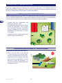
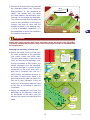
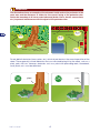
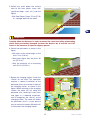
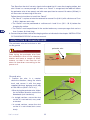
1
SUMMARY
General Information....................................................................................... 1
Installation of charging station ..................................................................... 2
Installation of perimeter wire ........................................................................ 6
Start up .......................................................................................................... 7
GENERAL INFORMATION
EN
Important
This manual is an addition to the user manual of the robot.
This robot, if equipped with a docking (charging) station, can operation in two different modes
based on the installation and configuration of the robot.
The standard operation, without changing the configuration, is described in the user manual. The
robot operates inside the mowing area detected by drop-off and grass sensors. On completion
of the work cycle, the robot runs along the mowing area until it encounters the guide wire. It then
follows this wire until it reaches the charging station.
This operating method is very fast and easy to install, however, there may be some passages
with no grass between one area and another, or where the quality of the lawn does not conform
to the robot specifications.
MD-CT-RO-01-ADDITION - XX - REV 3.3- EN - 10-2011 - (L50EEU)
In cases where the mowing area does not conform to the specifications, the robot can be
configured to operate with the drop-off and grass sensors turned off. In this case, the mowing
area must be marked by the perimeter wire.
The purpose of this integrative manual is to describe the installation and use of the robot with the
perimeter wire marking the outside boundary of the mowing area and all the objects inside that
must be excluded so that the robot can operate correctly.
1
User’s manual
INSTALLATION OF CHARGING STATION
Install the charging station by following the instructions described in the “INSTALLATION OF
CHARGING STATION” chapter of the user manual, except for the laying of the guide wire whose
function is performed by the perimeter wire described below.
SETTING UP OF THE PERIMETER WIRE
Before installing the perimeter wire, it is necessary to check the entire surface of the lawn.
Assess whether modifications or adjustments need to be made to the grassy surface during
the laying of the perimeter wire in order to allow the robot to operate properly.
• Proceed with the “Preparation and
defining of the work areas”.
• Installation of the perimeter wire. When
laying the perimeter wire, respect
the installation direction (clockwise)
and the rotation direction around the
flowerbeds (anti-clockwise). As shown
in the figure.
• Installation of the charging station and
power supply-transmitter unit.
PREPARATION AND DEFINING OF THE WORK AREAS
Preparation of the lawn to be mowed
1. Make sure the lawn to be mowed
is even and does not contain holes,
stones or other obstacles. If necessary,
prepare the lawn by filling in any holes
and removing any obstacles. If some
obstacles cannot be removed, it is
necessary to properly define them with
the perimeter wire.
User’s manual
HOLES
EN
2
NO
2. Check that no areas of the lawn exceed
the allowable slopes (see “Technical
Specifications”. In the presence of
slopes, the wheels may slip when
the robot detects the perimeter wire,
causing it to fall outside the perimeter.
The maximum slope that the robot can
mow on the conditions of the grassy
surface, the type of lawn and the
humidity present in the mowing area.
In case of boundary conditions, it is
recommended to have the conditions
assessed by a technician.
NO 40 %
40 cm (15,75 Inc.)
100 cm (39,3 Inc.)
0-40%
0-30%
31-40%
NO
OK
perimeter wire
31-40%
35 cm
NO
13,78 Inc.
Important
Areas with slopes greater than those specified cannot be mowed with the robot.
Therefore, position the perimeter wire in front of the slope so that it is excluded from
the mowing area.
Defining the boundary of work area.
5 cm
1,97 inc.
3. Check the whole surface of the lawn.
To make installation of the perimeter
wire easier, check the entire path.
The illustration shows a lawn with the
track for burying the perimeter wire.
During installation of the system, any
narrow passages must be identified.
A narrow passage is a section of lawn
connected to the main lawn with a
path that is narrower than 150 cm /
59.05 inches and difficult to reach by
the robot. In these cases, there is no
guarantee that the robot can reach this
area on its own; therefore, it may be
necessary to bring the robot by hand
to this area or to exclude it from the
installation.
70 cm
5 cm
27,56 inc.
1,97 inc.
70 cm
27,56 inc.
5 cm
5 cm
1,97 inc.
1,97 inc.
4-10 mt.
157,5 - 393,7 inc.
5 cm
1,97 inc.
35 cm
2 mt.
13,78 inc.
78,75 inc.
35 cm
13,78 inc.
35 cm
13,78 inc.
35 cm
35 cm
13,78 inc.
13,78 inc.
35 cm
13,78 inc.
drain cover
4. Define the boundaries and trace the
perimeters of the elements inside and
on the border of the work area that
obstruct the correct functioning of the
robot.
35 cm
13,78 inc.
35 cm
flowerbed
3
13,78 inc.
User’s manual
EN
Important
The illustration shows an example of the elements inside and on the perimeter of the
work area and the distances to follow for the correct laying of the perimeter wire.
Define the boundary of all iron or metal elements (drain covers, electric connections,
etc.) to prevent interferences with the signal of the perimeter wire.
EN
35 cm
wall
13,78 inc.
shower plate
35 cm
70 cm
13,78 inc.
27,56 inc.
35 cm
13,78 inc.
35 cm
13,78 inc.
protruding roots
Do not delimit obstacles (trees, poles, etc.) which do not obstruct the normal operation of the
robot. These generally include obstacles that can withstand being hit by the robot, such as a
plant, pole, wall, etc. However, obstacles such as a plant with protruding roots, flowerbeds,
small plants, etc. must be delimited.
OK
User’s manual
OK
plant
4
pole
5. Delimit any areas below the surface
level of the lawn (pools, areas with
significant drops, stairs, etc.) (see the
figure).
70 cm
27,56 inc.
- With Pool, Steps, Drops: 70 cm (27.56
in.) a danger point for the robot.
70 cm
27,56 inc.
EN
Important
Carefully follow the distances in order to prevent the robot from falling and breaking
and/or being irreversibly damaged. Increase the distance by at least 30 cm/11.81
inches in the presence of slopes or slippery ground.
6. Delimit the perimeters as shown in the
figure.
- With paths at the same height as the
lawn: 5 cm (1.96 in.)
- With paths higher than the lawn: 35
cm (13.78 in.)
35 cm
13,78 inc.
- With the presence of an enclosing
wall: 35 cm (13.78 in.)
35 cm
13,78 inc.
5 cm
1,97 inc.
7. Before the charging station, install the
“Recall on the Wire.”This operation
requires a special installation of the
perimeter wire in the section in front of
the charging station, as shown in the
figure. When returning to the charging
station, the robot will run along the
perimeter wire, touching it every now
and again in a rebound movement,
until it recognises the “Recall” to the
charging station. The robot will follow
the perimeter wire in a more precise
way for around 10 meters (33 feet) until
it encounters the charging station.
5 cm
1,97 inc.
70 cm
27,56 inc.
5 cm
1,97 inc.
70 cm
27,56 inc.
5 cm
1,97 inc.
4-10 mt.
5 cm
1,97 inc.
157,5 - 393,7 inc.
5 cm
1,97 inc.
35 cm
2 mt.
13,78 inc.
78,75 inc.
35 cm
13,78 inc.
35 cm
13,78 inc.
35 cm
35 cm
13,78 inc.
13,78 inc.
35 cm
13,78 inc.
5
User’s manual
The “Recall on the wire” not only signals to the robot that it is near the charging station, but
also if there is a narrow passage. As soon as a “Recall” is recognised, the robot will follow
the perimeter wire at low speed, and with more precision for around 10 meters (33 feet). It
will then return to bouncing off the wire.
Follow these instructions to install the “Recall.”
• The “Recall” is a piece of wire that extends for around 2 m (6.6 ft.) with a distance of 5 cm
(1.96 in.) between each wire.
• The “Recall” must be positioned at a distance of 4 and 10 m. (13.2 - 33 ft.) before the
charging the station.
EN
• The “Recall” must be positioned in the section before any narrow passages that are less
than 2 meters (6.6 feet) long.
8. Connect the perimeter wire to the charging station as indicated in the chapter “INSTALLATION
OF CHARGING STATION” of the user manual.
INSTALLATION OF PERIMENTER WIRE
The perimeter wire can be buried or laid
on the ground.
perimeter wire
Important
Start laying the perimeter wire from
the installation zone of the charging
station and leave a couple of extra
meters, so that it can then be cut
down to size when connecting to the
power unit.
Max.
5 cm (1,96 inc.)
Ground wire
1. Position the wire, in a counter
clockwise direction, along the whole
track and secure it with the pegs
supplied (distance between each peg
of 100÷200 cm (39.37÷78.74 in.)).
NO
– When laying the perimeter wire, follow
the installation direction around the
flowerbeds (anti-clockwise).
– In straight sections, secure the wire
so that it is not too taut, wavy and/
or twisted.
wire fastening pegs
– In curved sections, secure the wire
so that it is not twisted, but curves
nicely.
User’s manual
6
perimeter wire
Buried wire
1. Dig the ground in a regular and symmetrical manner with respect to the line traced on the
ground.
2. Position the wire in an anti-clockwise direction along the track a couple of centimetres deep
(around 2÷3 cm (0.7874÷ 1.1811 in.)) so that the quality and intensity of the signal received
by the robot is not reduced.
3. During the laying of the wire, it may be necessary to secure it in some parts with special pegs
to hold it in position when covering with dirt.
4. Cover all the wire with the soil and make sure it does not twist, but remains straight and that
the curved sections are neat and tidy.
EN
Important
In sections where it is necessary to
pass two parallel wires (e.g. to delimit
a flowerbed), make sure they are laid
on top of each other at a minimum
distance of 1 cm. (0.40 in.)
NO
Max 1 cm
(0,40 inc.)
START UP
On first use, the robot must be configured to operate with the outside perimeter. This only
has to be done once. After which, this configuration will remain even if the robot is turned off.
Press “ON” to turn on the robot and keep it pressed for about 4-5 seconds until the “ON” and
“PAUSE” leds start flashing alternatively. Release the “ON” key while only the “PAUSE” led is
flashing.
PAUSE
LOW BATTERY
START
STOP
PAUSE
LOW BATTERY
START
STOP
PAUSE
LOW BATTERY
HIGH BATTERY
ON
7
OFF
ON
HIGH BATTERY
ON
OFF
ON
HIGH BATTERY
ON
OFF
ON
START
STOP
4 sec.
User’s manual
Important
If this operation was done by mistake, return to the standard configuration by
following this operation. Press “ON” to turn on the robot and keep it pressed for
about 4-5 seconds until the “ON” and “PAUSE” leds start flashing alternatively.
Release the “ON” key while the “ON” led is flashing.
At this point, the robot can be started as described in the “START UP. ROBOT WITH CHARGING
STATION” section of the user manual.
EN
User’s manual
8