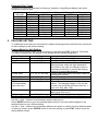
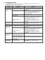
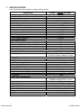
1
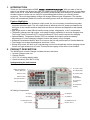
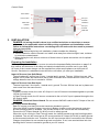
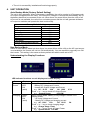
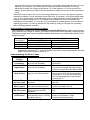
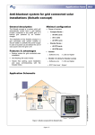
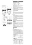
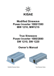
Abso Sinewave
Inverter-Charger
3000W (IC1230150)
Owner’s Manual
For safe and optimum performance, the KISAE Abso Inverter-Charger 3000 must be used
properly. Carefully read and follow all instructions and guidelines in this manual and give special attention
to the CAUTION and WARNING statements.
PLEASE KEEP THIS MANUAL FOR FUTURE REFERENCE
Disclaimer
While every precaution has been taken to ensure the accuracy of the contents of this guide, KISAE
Technology assumes no responsibility for errors or omissions. Note as well that specifications and
product functionality may change without notice.
Important
Please be sure to read and save the entire manual before using your KISAE Inverter-Charger.
Misuse may result in damage to the unit and/or cause harm or serious injury. Read manual in its
entirety before using the unit and save manual for future reference.
Product Numbers
IC1230150
Abso Inverter-Charger 3000
Document Part Number
MU IC1230 Rev A
1. INTRODUCTION
Thank you for purchasing the KISAE Abso Inverter-Charger. With our state of the art,
easy to use design, this product will offer you reliable service by providing AC power for your home,
cabin, boat, RV or Trailer and recharge your battery automatically when utility AC is available. The
sinewave output inverter can run many AC-powered appliances when you need AC power
anywhere. The multi-stage battery charger will charge different types of batteries. The transfer
switch will automatically switch the load to the battery power when the utility power is interrupted.
Feature Highlights
• The inverter provides true sinewave output power for your microwave, entertainment system,
computer and other loads. The AC output power is identical to the AC power provided by the
utility grid. It can handle sensitive loads such as dimmer switches and appliances with speed
controls.
• High surge power to start difficult load like sump pumps, refrigerators, or A/C compressors.
• The battery charger has high output, multi-stage charging capability to minimize charging time.
The Power Factor Corrected (PFC) input minimizes AC input current required for charging.
• Optional Battery Temperature Sensor (BTS) is available and used to sense the battery
temperature to correct charging voltage to ensure the battery is fully charged.
• A Manual Equalization Mode is built-in to improve the life and performance of flooded batteries.
• The charger can charge dead batteries as low as 3 volts.
• During utility mode, the built-in AC load sensing circuit will automatically reduce charging current
if there is a high demand on AC load. This avoids the tripping of the shore circuit breaker.
2. PRODUCT DESCRIPTION
The KISAE Abso Inverter-Charger includes the items list below.
• Inverter-Charger base unit
• Remote Display
• 25 ft (7.6 m) remote display cable
• Owner’s manual (P/N: MU IC1230)
Understanding the unit features
Front Panel
AC Input 1 (30A)
Battery Temperature
Sensor (BTS) port
AC Output (30A)
Remote 1 Port
AC Input 2 (30A)
Remote 2 Port
AC Wiring
Compartment
DC Input Terminal +
AC Input wire
opening
DC Input Terminal -
AC output wire
opening
AC Wiring Compartment
AC Input 1
AC Output 1
AC Input 2
AC Output 2
AC GND bus for AC
Input 1 and 2
AC GND bus for AC
Output 1 and 2
Control Panel
Reset button
Power button
DC Input
Terminal +
Status LED
Indicator
Ventilation
Fan opening
DC Input
Terminal GND Stud
3. INSTALLATION
DANGER: All wiring should be done by a certified technician or electrician to ensure
adherence to the applicable electrical safety wiring regulations and installation codes.
Failure to follow these instructions can damage the unit and could also result in personal
injury or loss of life.
CAUTION: Before beginning unit installation, please consider the following:
• The unit should be used or stored in an indoor area away from direct sunlight, heat, moisture
or conductive contaminants.
• When placing the unit, allow a minimum of three inches of space around the unit for optimal
ventilation.
Preparing for Installation
Before you begin the installation, be sure to review the Important Safety Instruction on page 3 of
this manual and be aware of all safety and electrical codes which must be met in your area.
AC Input of the inverter charger can be supplied from either a split-phase or a dual-input AC
Source. See below to understand more about the unit before you start your installation.
Input AC Source from Split-Phase:
The split-phase AC source has 2 lines, 1 neutral and 1 ground. The two 120Vac lines are 180
degree out of phase with each other with a total of 240Vac when measured from line to line. The
voltage between each line to neutral is 120Vac.
Input AC Source from Dual Input:
The dual input has 2 line inputs, 1 neutral and 1 ground. The two 120Vac lines are in phase and
must come from the same source.
AC Loads:
In Battery-Inverter mode, the unit’s AC Output L1 and L2 lines are connected together to provide
120Vac on both lines.
In Pass-Through mode, the AC source connected to the unit’s AC input is passed through to the
AC Output (load).
DANGER: Electrical Shock Hazard. Do not connect 240VAC load to the AC Output of the unit.
AC Output Neutral Bonding:
Each AC source must have its neutral conductor bonded to ground.
When the KISAE Inverter-Charger is running in Battery-Inverter mode, the internal neutral-toground bonding system is enabled. The unit will act as an AC source and will automatically
connect the AC Output Neutral (N1 & N2) circuit to safety ground.
When the unit is running in Pass-Through mode, the internal neutral-to-ground bonding system
is disabled. The unit will not act as an AC source and the AC Output (N1 & N2) to safety ground
is disconnected inside the unit. Therefore, the AC Input source that is connected to the InverterCharger should have its own neutral-to-ground connection. If not, have an electrician look into
bonding the AC source’s neutral to ground at your AC source.
Typical Wiring block diagram of the Inverter-Charger
Inverter
AC Output
Panel
(AC Output)
Input:
AC Source
Inverter-Charger
(IC1230150)
DC
Disconnect
Switch
DC Fuse or Over
Current Protective
Device
12V
Battery
Bank
Main AC
Input Panel
(AC Input)
12V Battery Bank:
• The use of a deep cycle battery is highly recommended for power inverter application.
• For battery size, you need to identify what you wish to operate, and for how long. KISAE
recommends that you purchase as much battery capacity as possible. See more on Estimated
Run Times in Section 4.
DC Cable:
• All DC cables used require multi-strand insulated cable.
• The DC cables must be copper and must be rated 105°C minimum.
• Based on National Electrical Code, cable size of 4/0 AWG is required for cable length < 5 ft.
Use of smaller gauge cable or longer cable length may cause the inverter to shutdown under
heavy load and may also melt the cable insulation and catch fire and can result in death or
serious injury.
DC Grounding:
• The chassis of the unit has to be grounded properly.
• For Marine application, the DC grounding cable size may be one size smaller than the
minimum size conductor required for the DC current carrying conductors, providing the
overcurrent protection device in the DC positive conductor is rated no greater than 135% of
the capacity of the DC grounding conductor, and the conductor is no smaller than #16AWG.
• For Recreational Vehicle application, the unit has to be grounded to the vehicle chassis with a
minimum #8 AWG copper conductor with either green insulator or bare wire.
Important: The unit is grounded through the ground stud of the unit .
DC Fuse or Over Current Protective Device:
• A DC-rated fuse or a DC-rated over-current protective device connected along the DC positive
line is required.
• Based on the National Electrical Code requirement, a fuse or circuit breaker with a minimum of
350 Adc is required.
• Based on the size of your 12V Battery Bank, determine the overall short circuit current rating
of the battery bank from the battery manufacturer. The fuse or circuit breaker chosen must be
able to withstand the short circuit current that may be generated by the battery bank.
• For Marine application, the over current protective device needs to be installed within 7 inches
(17.8cm) from the battery positive terminals.
DC Disconnect Switch:
• Select a DC Disconnect Switch with the same or higher rating of the selected fuse or over
current protective device.
• The DC Disconnect Switch is used to disconnect the DC power between the unit and the
battery bank during service, maintenance or trouble shooting.
Main AC Input Panel (wire size and breaker size):
• For Dual AC Input, #6 AWG AC Input wire is required.
• For Split Phase AC Input, #10 AWG AC Input Wire is required for all the AC connections
between the AC source and the AC Input port.
• To meet CSA, UL and electrical code requirements and to protect system wiring, the AC input
line must be provided with an overcurrent protection device for which a 30A branch circuit
breaker is required to connect each AC Line to the unit’s AC Input.
Important: Follow the electrical and/or building code when you connect the unit to any AC
source.
Inverter AC Output Panel (wire size and breaker size):
• #10 AWG wire is required for all AC Output connections based on the full 30A pass-through
rating between the unit and the AC Inverter AC Panel.
• To meet CSA, UL and electrical code requirements and to protect system wiring, the AC input
line must be provided with an overcurrent protection device for which a maximum 30A branch
circuit breaker is required to connect each AC Output Line to the unit’s AC Output. If an AC
Output wire of smaller than #10 AWG is used, then the overcurrent protection device will have
to be smaller. Follow the electrical and or building code to choose your protection device rating.
Installing the Inverter-Charger System
WARNING: Electrical Shock Hazard
The unit ‘On/Off’ switch does not disconnect the DC power from the battery. Use the DC
Disconnect Switch or disconnect the DC input cable connection to disconnect the DC
power from the battery before working on any circuits connected to the unit. Use the AC
circuit breaker to disconnect any AC power to the unit before servicing. Failure to follow
these instructions can result in death or serious injury.
Installation:
• Choose an appropriate mounting location. The unit should be installed away from the battery
in a separate well ventilated compartment. Do not install the unit in any compartment
containing flammable gases or liquids like gasoline or in the battery compartment where they
may be explosive hydrogen gas from the batteries present.
• The length and size of the DC cables will affect unit performance.
• For indoor use, the unit can be mounted in any direction except with the fan panel (panel with
fan opening) facing upwards or downwards.
• The location to install the unit has to have a normal air temperature between 0°C – 60°C
(32°F-140°F). The cooler the better, or overheating may result.
• Use the mounting template below to mark the positions of the mounting screws.
• Drill the 4 mounting holes and place the Inverter-Charger in position and fasten the unit to the
mounting surface.
AC Input Wire Connection:
DANGER: Make sure all the AC wiring being connected to the unit is physically
disconnected or by opening the circuit breaker from the electrical sources. All wiring
must be done in accordance with local and national electrical wiring codes.
CAUTION: The terminal block is split into AC Input and AC Output sections. Damage will
occur to unit if it is wired incorrectly.
• The AC and DC wire cannot be mixed together in the same conduit.
• The AC input and AC Output wire should be separated out through the two AC knockouts
located at the bottom of the unit.
• Remove AC compartment cover by unscrewing the four screws located on the four corners of
the AC compartment cover.
• There are two ground bus locations inside the AC Wiring Compartment. The ground bus
•
•
•
•
located at the left hand side of the AC compartment is intended for use with AC Input ground
wire. The right hand side ground bus is intended for use with AC Output ground wire.
Remove the left hand side AC knockout. Install the strain-relief clamp in the AC knockout.
Run the AC input wire through the strain relief clamp.
Connect AC Input wire Line 1 to L1, Neutral to N and Line 2 to L2 of the terminals and Ground
to ground bus.
Secure the strain-relief clamp.
AC Output Wire Connection:
• Similar procedure as connecting the AC Input wire: remove the right hand side AC knockout.
Install the strain-relief clamp in the AC knockout.
• Run the AC output wire through the strain relief clamp.
• For Line for Dual Output, connect AC output wire Line 1 to L1, Neutral 1 to N1 and Line 2 to L2,
Neutral 2 to N2 of the terminals and Ground to the ground bus.
• Secure the strain relief clamp.
• Place the AC compartment cover and secure with the four screws.
Unit Chassis Grounding Connection:
DANGER: The unit chassis has to be grounded properly. Never operate the InverterCharger without proper grounding. Failure to do so may result in death or serious injury.
• Connect the grounding cable’s ring terminal to the unit ground screw.
• Connect the other side of the cable to the common grounding point.
DC Input Connection:
CAUTION: Reversing the DC Input terminal will damage the unit and it cannot be
repaired. Damage caused by reverse polarity connection is not covered by the warranty.
• Connect one end of the negative DC input cable to the Inverter-Charger DC negative terminal.
Connect the other end of the negative DC input cable to the battery negative terminal.
• Make sure the DC Disconnect Switch is in the OFF position.
• Connect one end of the positive DC input cable to the Inverter-Charger DC positive terminal.
Connect the other end of the positive DC input cable to one of the terminals of the DC
Disconnect Switch.
• Connect a DC input cable between the other terminal of the DC Disconnect Switch and one
side of the terminal of the fuse holder.
• Connect a DC input cable between the other terminal of the fuse holder and the battery
positive terminal.
• Install the selected fuse to the fuse holder.
• Turn DC Disconnect Switch to ON position.
Remote Display Connection:
• Install the RJ45 standard cable to your desired location. Please note polarity.
• Connect one end of the RJ45 cable to one of the two Remote 1or 2 port on the unit and the
other end of the cable to the Display Panel. Please note the polarity.
Optional Battery Temperature Sensor Connection:
• Insert the RJ45 plug from the battery temperature sensor to the Inverter-Charger’s Battery
Temperature Sensor port. Please note the polarity
• Select the battery for which you would like to monitor the temperature, connect the Battery
Temperature Sensor to the negative terminals of this battery.
Test the Installation:
• Switch DC disconnect switch and all AC circuit breaker to ON to provide DC power to the unit.
• The status LED display will turn on. If AC input source is available, ‘Charging’ green LED turns
On. This indicates the unit is running in by-pass mode meaning AC output is running from the
AC input source.
• Disconnecting the AC input source by turning OFF the 30A branch breaker. ‘Battery Power’
green LED will turns On. This indicates the unit is running in battery power mode.
• Plug in a small AC load like a 40W table lamp or small appliance to the AC socket to verify AC
is available.
• The unit is successfully installed and functioning properly.
4. UNIT OPERATION
Auto Backup Mode (Factory Default Setting)
The unit is fully automatic. When utility power is available, the unit is running in AC bypass mode.
AC output is supplied from the utility. The internal AC charger is ON and will automatically top up
the battery bank that is connected to the unit. When there is a power failure from the utility or an
AC source is not available, the unit will run on battery power and the unit will generate sinewave
AC output to maintain and operate the load continuously.
Factory Default Setting
Charger
On
Inverter
On
SCR set
30A
Power Save
Off
Battery Type
AGM
Set Current
150A
EQ Mode
Off
Fault Alarm
On
Display Background Brightness
80%
Background Light Timer
3 minutes
Non-Backup Mode
Same as Auto Backup Mode but when there is a power failure of the utility or the AC input source
is not available, the inverter will not turn ON automatically. You are required to manually turn ON
the inverter. This setting is the same as factory default but with Inverter set to OFF.
Understanding the Display Functions
LED Indicator functions on unit display and remote display:
Status
Battery
Power
Display
Green
LED
ON
(solid)
Charging
Green
LED
ON
(solid)
Function/Status
Battery Power Mode. Remote LCD Display shows:
- Battery DC Voltage and Current
- Inverter AC Output Voltage and Current
e.g. DC: 12.5V
30A
AC: 120V
2.7A
Press ‘+’ or ‘-‘ key to check AC Output Power.
e.g. System Power
0.33 KW
Pass-Through Mode. Battery is fully charged. Remote LCD
Display shows:
- AC Input Voltage and Current
- Battery DC Voltage and charging current
e.g. AC: 120V
15A
DC: 12.0V
5A
Press ‘+’ or ‘-‘ key to check charging stage.
e.g. Charge Stage Float
Press ‘+’ or ‘-‘ key to check AC Input Power.
e.g. System Power 1.80 KW
Green
LED
ON
(flashing)
Fault
Red ON
(solid)
Pass-Through Mode (AC mode). Battery Charging is in progress.
Remote LCD Display shows:
- Battery DC Voltage and charging current
- AC Input Voltage and Current
e.g. AC: 120V
20A
DC: 12.0V
50A
Press ‘+’ or ‘-‘ key to check charging stage.
e.g. Charge Stage ABS
Press ‘+’ or ‘-‘ key to check AC Input Power.
e.g.
System Power
2.4 KW
Unit has shutdown. Display shows error code and error message.
- Low battery shutdown
e.g. FAULT: E01
Low Battery
Push Button Functions on Unit
A beeping sound will occur every time that any button on the unit is triggered.
Button
Power
Reset
Function
Turns unit On/Off. Press and hold for 1 second to turn unit On/Off
Reset the unit: Press once to reset the unit. This may be required when an error
is detected on the unit
Push Button Functions on Remote Display
A beeping sound will occur every time any button on the unit is triggered.
Button
O
Enter
+
EXIT
Function
Turns LCD display On/Off. Press and hold for 2 seconds to turn display On/Off.
Display shows unit model number and revision.
e.g.
Inverter/Charger
3000W REV 1.1
Save the selected setting or go to the next stage
Scroll up on the menu
Scroll down on the menu
Exiting or entering the feature setting mode
Understanding the Charger Functions
Three-Stage Charging:
The Three-Stage Charging algorithm has a Bulk, then Absorption and then Float sequence.
During the Bulk stage, the battery accepts the maximum constant current from the charger. In
the Absorption stage, the battery voltage is held to constant voltage and the charging will
slowly reduce. In Float stage, the charger continuously produces voltage at a lower level to
fully top up the battery and maintain the battery in a fully charged state.
The charger will automatically restart the charging cycle in Bulk stage if the battery is
discharged to 12.5V. Also, after seven days, the charger will automatically restart the
recharging cycle to refresh the battery.
Battery Type:
Three types of battery setting (GEL, AGM and Flooded) are available. See reference battery
charging voltage as shown:
Battery Type
GEL
AGM
Flooded
Absorption
14.4 V
14.3 V
14.4 V
Float
13.8 V
13.45 V
13.5 V
Equalization
N.A.
N.A.
16.0 V
Equalize the Flooded Battery:
For Flooded battery type, equalization mode is available. Use the following procedure to
equalize the flooded battery. See also section 5 on setting EQ mode for flooded battery.
DANGER: Explosion Hazard. The flooded battery generates explosive gases during
equalization. Follow all the battery safety precautions listed in the manual.
CAUTION: Risk of Battery and Equipment damage. Only a Flooded lead-acid battery can
be equalized. Consult your battery manufacturer or read the battery manual when you try to
equalize your batteries. Disconnect any DC load connected to the battery, as during
equalization mode, the charger will produce 16V to the batteries. You must monitor the
battery specific gravity throughout the equalization to determine the end of the equalization
cycle.
When EQ mode is set to ON, the unit will charge batteries in one full cycle before it starts to
equalize the battery. Check the battery electrolyte level. If necessary, refill with distilled water
only. All cells should have similar electrolyte levels. If distilled water is added, batteries must
undergo a complete charge cycle. The charger cannot determine when to terminate the
equalization of the battery. A 1 hour time-out is intended as a safety feature to terminate the
equalizing process. You can re-activate the EQ mode by setting it ON again as necessary
after checking batteries manually.
Optional Battery Temperature Sensor Feature:
Optional Battery Temperature Sensor KISAE Part Number #BTS-10K is highly recommended
to be used with the charger to protect your battery and provide better charging voltage accuracy.
The battery temperature sensor senses the battery temperature and makes adjustments to the
charging voltage.
Battery
Battery Charging Voltage Adjustment from 25 °C normal setting
Temperature
Flooded and GEL type
AGM type
< 25 °C
+ 0.027 V /°C
+ 0.021 V /°C
25 °C
0V
0V
> 25 °C
- 0.027 V /°C
- 0.021 V /°C
Note: The charger will terminate battery charging when the BTS senses the battery
temperature reaching 60 °C. It will not continuously make voltage adjustments when the
battery temperature drops to below 0 °C.
Understanding the Error Codes
Error Code on
Display
Fault: E01
Low Battery
Fault: E02
High Battery
Battery voltage is too low
and unit has shutdown
Battery voltage is too high
and unit has shutdown
Fault: E03
Temp Protect
Internal temperature is too
high and unit has shutdown
Fault: E04
AC Over Load
Fault: E05
Short Protect
Fault: E06
INV Over Load
Inverter AC Output has
overload
Inverter output is short
circuited and has shutdown
Inverter output voltage is too
high or too low and has
shutdown
Battery temperature is high
and warning occurs. Unit will
shutdown shortly.
Fault: E08
BTS Protect
Condition
Corrective Action
Recharge battery immediately and
restart unit.
Check battery voltage or determine if
any external charger with high voltage
output is connected to the battery bank
Check if any object has blocked the air
flow of the unit. Check environmental
temperature. The unit will restart when
the internal temperature has reduced
to about 50 °C.
Check AC load connected and restart
the unit.
Check load connected to the AC
output and restart the unit.
Check unit and load and restart the
unit.
Check battery. Check ventilation in
battery compartment. Check
environmental temperature.
Estimated Run Times
Following run times are estimates for reference, based on using different battery bank sizes.
Actual run times may vary.
Estimate run time on different 12V Battery Bank Size
AC Load
60AH
120AH
180AH
240AH
300AH
50 W
11 hrs.
22 hrs.
33 hrs.
44 hrs.
55 hrs.
100 W
5 hrs.
11.5 hrs.
17 hrs.
23 hrs.
29 hrs.
200 W
2.5 hrs.
5 hrs.
8 hrs.
11 hrs.
13.5 hrs.
500 W
49 mins
2 hrs.
3 hrs.
4 hrs.
5 hrs.
1000 W
15 mins
49 mins
1.5 hrs.
2 hrs.
2.5 hrs.
1500 W
8 mins
27 mins
49 mins
1 hr
1.5 hrs
2000 W
N.R.
15 mins
34 mins
49 mins
1 hrs
2500 W
N.R.
11 mins
25 mins
37 mins
49 mins
3000 W
N.R.
N.R.
17 mins
27 mins
37 mins
Note: N.R. – Not Recommended
5. FEATURE SETTING
To understand more about the unit features, read the following section and follow the instructions
to make changes to the desired setting.
Feature Menu for Unit Setting
To enter feature setting mode, on remote display, press and hold ‘EXIT’ button for 5 seconds.
The feature setting menu will display on the screen with the following sequence:
Menu Sequence
Charger
Inverter
SCR set
Setting
On/Off
On/Off
15, 20,25,30 A
Power Save
0, 5, 10, 15, 20, 50W
Battery Type
Set Current
EQ Mode
(Flooded battery
type use only)
AGM, GEL, Flooded
60 – 150A (5A step)
On/Off
Fault Alarm
Brightness
Backlight Timer
On/Off
10-100% (10% step)
1–9 mins (1 min step)
Function
Turns Battery Charger On/Off
Turns Power Inverter On/Off
Set AC Input Source Power Breaker Rating.
During by-pass mode with high demand for
AC power for the load, the charger current is
reduced automatically to prevent the tripping
of the AC Source power breaker.
Lowers power draw when low power loads are
connected to inverter
Select battery type
Set charger current
EQ mode is used to equalize the flooded
battery. The charging voltage is 16V and the
current is set to half the set bulk current for 1
hour (min: 30A, Max: 75A).
Silent mode: Enable or Disable the audible
alarm when fault occur
Set LCD Background lighting brightness
Set timer ON for LCD background lighting
Use the ‘+’ and ‘-‘ button to scroll between feature setting menu.
Press ‘ENTER’ button to go to the selected feature and you can now make changes on the
selected feature to your desired setting.
Use the ‘+’ and ‘-‘ button to scroll between different set values or setting. Once the desired values
or setting is chosen, press ‘ENTER’ button to save the setting or press ‘EXIT’ button to quit the
setting without saving.
6. TROUBLESHOOTING
To troubleshoot the unit, please note the error code displayed on the main unit and review
“Understanding the Error Codes” in section 4.
Problem
Symptom
Solution
Condition: Inverter setting is set to Off, AC source is available
No AC Output. Unit is turned Off
Turn unit ON by following the instruction in
Charging LED
Section 4
is off.
AC source is not available
Check AC source.
Check AC input branch breaker is off
Check AC connection between the AC
source and the unit
AC Input breaker is turned
Check AC Load and reset AC Input breaker
off or tripped
No DC power to unit
Check DC fuse, DC Disconnect switch (if
installed) and check if Branch breaker is
either blown or turned OFF
Battery voltage is low
Use a separate charger to boost battery
(<7Vdc)
voltage to above 7V and unit can be
restarted.
30A Circuit Breaker is
Check load and reset the AC breaker and
No AC output.
tripped and check fault code
verify the error condition and make
Fault LED is
correction.
on
Condition: Inverter setting is set to On, AC source is not available
No AC Output. Unit is turned Off
Turn unit ON by following the instruction as
Battery Power
in Section 4
LED is off
No DC power to unit
Check DC fuse, DC Disconnect switch (if
installed) and check if Branch breaker is
either blown or turned OFF
Battery voltage is low
Use a separate charger to boost battery
(<7Vdc)
voltage to above 7V and unit can be
restarted.
No AC Output. AC breaker connected
Switch on or reset breaker
Battery Power
between the Unit AC Output
LED is on
to load is turn off or tripped
Check AC Load Sense
Decrease AC load sense power level or
setting. AC Output power
increase AC load connected to AC Output.
consumption is lower than
the AC Load
No AC output.
Check error code
Verify the error condition and make
Fault LED is
correction.
on
7. SPECIFICATIONS
Note: Specifications are subject to change without notice.
Specification
Inverter
AC Output Power
AC Output Current
AC Surge Power (Peak)
AC Output Voltage/Frequency
AC Output Waveform
Nominal DC Input Voltage
No Load battery draw
DC Input Voltage Operating Range
Under Voltage Alarm
Under Voltage Alarm Recovery
Under Voltage Shutdown
Under Voltage Recovery
Over Voltage Shutdown
AC Transfer Switch
Transfer Time
Transfer Relay Rating
AC Input Source Current Setting (SCR set)
AC Input L1, N1
AC Output Line 1 (L1, N1) and Line 2 ( L2, N2)
Remote Display
Display Panel Port
LCD Display
Battery Temperature Sensor Port
BTS Port
Charger
Charging Voltage Range
Floated Voltage Range
Charging Control
Charger Current (max)
Charger Current Setting
Equalization Voltage (Flooded battery setting)
Equalization Current (Flooded battery setting)
Efficiency
Safety and Environmental
Conformance
Agency Markings
Operating Temperature
Storage Temperature
Relative Humidity
Operating Altitude
Weights and Dimensions
Weights
Dimensions
KISAE BATTERY
Abso Inverter-Charger
3000
3000W
25A
6000W (5 seconds)
120 VAC / 60 Hz
True Sinewave (<5% THD)
12.5 VDC
< 3.5 A nominal, <1A with load sense
11.0 - 16.0 VDC
11.8 VDC
12.2 VDC
10.5 VDC
11.5 VDC
16.5 VDC
< 20 ms
30A
15, 20, 25A, 30A
30A
30A
RJ45 socket
AC Input / Output Voltage & Current
DC Input / Output Voltage & Current
RJ45 socket
7.0 – 16.0 VDC
13.45 – 13.8 VDC
3 Stages (Bulk/Absorption/Float)
150A
60A – 150A
16.0 VDC
½ Bulk Current (min 30A, max 75A)
>80%
Conforms to UL 458
Certified to CSA C22.2 no. 107.1
cETLus
0°C to 40°C (32°F to 104°F)
-20°C to 60°C (-4°F to 140°F)
5-90% noncondensing
Up to 9,843ft (3000m) above sea level
66 lb (30 kg)
15.4 x 13.4 x 7.8” (392x340x197mm)
CAR BATTERIES