1
PLEASE KEEP THIS MANUAL FOR FUTURE REFERENCE
USER’S MANUAL
Supreme Combi
Inverter Charger
Disclaimer
While every precaution has been taken to ensure the accuracy of
the contents of this guide, WhisperPower BV assumes no responsibility for errors or omissions. Note as well that specifications
and product functionality may change without notice.
Important
Please be sure to read and save the entire manual before using
your WP-BC Surpreme Battery Charger. Misuse may result in
damage to the unit and/or cause harm or serious injury. Read
manual in its entirety before using the unit and save manual for
future reference.
Product Numbers:
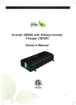
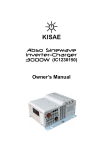
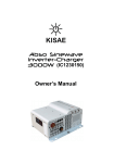
61121040 WP-Supreme Combi 1000-40
61122055 WP-Supreme Combi 2000-55
Service Contact Information
Email:[email protected]
Phone : +31 (0) 512 571 555
Web :www.whisperpower.com
1000W-40A
2000W-55A
- Convert 12V battery power to AC power
- Sinewave output ideal for running
demanding motorloads, sensitive electronics
and battery rechargeble devices
- Multistage charger ensures batteries
are recharged safety and efficiently
- Runs small microwave ovens, computers,
televisions, powertools and more
- Detachable remote on/off display
can be mounted anywhere
- Ideal for boats, trucks and caravan
Table of Contents
1. Introduction
2. Product description
3. Installation
4. Unit operation
5. Troubleshooting
6. Specifications
7. Warranty
1. INTRODUCTION
Thank you for purchasing the WhisperPower Inverter-Charger.
With our state of the art, easy to use design, this product will offer
you reliable service by providing AC power and 5V USB power
for your home, cabin, boat, RV or Trailer using battery power and
recharge your battery automatically when utility AC is available.
The Sinewave Inverter-Charger can run many AC-powered appliances when you need AC power anywhere. The 5V USB power
can charge many USB-powered devices. The multi-stage battery
charger will charge different type of batteries.
This manual will explain how to use this unit safely and effectively.
Please read and follow these instructions and precautions carefully.
Important safety information
This section contains important safety information for the Sinewave Inverter-Charger. Each time, before using the unit, READ
ALL instructions and cautionary markings on or provided with the
unit, and all appropriate sections of this guide.
The Sinewave Inverter-Charger contains no user-serviceable parts.
See Warranty section for how to handle product issues.
WARNING: Fire and/or Chemical Burn Hazard Do not
cover or obstruct any air vent openings and/or install
in a zero-clearance compartment. WARNING: Failure
to follow these instructions can result in death or
serious injury.
- When working with electrical equipment or lead acid batteries,
have someone nearby in case of an emergency.
- Study and follow all the battery manufacturer’s specific precautions when installing, using and servicing the battery connected
to the inverter.
- Wear eye protection and gloves.
- Avoid touching your eyes while using this unit.
- Keep fresh water and soap on hand in the event battery acid
comes in contact with eyes. If this occurs, cleanse right away
with soap and water for a minimum of 15 minutes and seek
medical attention.
- Batteries produce explosive gases. DO NOT smoke or have an
open spark or fire near the system.
- Keep unit away from moist or damp areas.
- Avoid dropping any metal tool or object on the battery. Doing
so could create a spark or short circuit which goes through the
battery or another electrical tool that may create an explosion.
WARNING: Shock Hazard. Keep away from children!
Avoid moisture. Never expose unit to snow, water
etc. Unit provides 230 Vac, treat the AC output
socket the same as regular wall AC sockets at home.
WARNING: Explosion hazard!
DO NOT use the unit in the vicinity of flammable
fumes or gases (such as propane tanks or large
engines). AVOID covering the ventilation openings.
Always operate unit in an open area. Prolonged
contact to high heat or freezing temperatures will
decrease the working life of the unit.
Ce emc information
This equipment has been tested and found to comply with the
limits for CE EMC standard. These limits are designed to provide
reasonable protection against harmful interference in a residential
installation. This equipment generate, uses and can radiate radio
frequency energy and, if not installed and used in accordance
with the instructions, may cause harmful interference to radio
communications. However, there is no guarantee that interference
will not occur in a particular installation. If this equipment does
cause harmful interference to radio or television reception, which
can be determined by turning the equipment off and on, the user
is encouraged to try to correct the interference by one or more of
the following measures:
- Reorient or relocate the receiving antenna.
- Increase the separation between the equipment and the receiver.
- Connect the equipment into an outlet on a circuit different from
that to which the receiver is connected.
- Consult the dealer or an experienced radio/TV technician for help.
Limitations on use
Do not use in connection with life support systems or other medical equipment or devices.
2. PRODUCT DESCRIPTION
The Sinewave Inverter-Charger includes the items list below.
- Inverter-Charger base unit (one of the following models)
1000W Unit: Sinewave Inverter 1000W with 40A charger
2000W Unit: Sinewave Inverter 2000W with 55A charger
- Owner’s manual
3. INSTALLATION
WARNING: It is recommended that all wiring be done
by a certified technician or electrician to ensure
adherence to the applicable electrical safety wiring
regulations and installation codes. Failure to follow
these instructions can damage the unit and could
also result in personal injury or loss of life.
CAUTION: Before beginning unit installation, please
consider the following: The unit should be used or
stored in an indoor area away from direct sunlight,
heat, moisture or conductive contaminants. When
placing the unit, allow a minimum of three inches of
space around the unit for optimal ventilation.
Understanding the unit features
AC Output Front Panel
USB Output
AC Wiring
Compartment:
AC Output Port 2
Status Indicator
AC Output strain relief
Display
AC Input strain relief
AC Input Source and Branch Breaker:
- Standard AC Input wire is required for all the AC connections
between the AC source & the AC Input port, and the AC Output
ports to load.
- A 16A branch circuit breaker is required to connect between AC
Input source and unit’s AC Input port.
Important: Follow the electrical and or building code when you
connect the unit to any AC source.
AC Output Port 1
AC
Ground
AC Input
Port
Select
button
On/Off
button
DC Input Rear Panel
Fan opening
DC Input Terminals
Preparing for Installation
Typical Wiring block diagram of the Power Inverter:
AC Output
Port
1, 2 & USB
AC Input
Source
+
DC
InverterDisconnect
Charger
Switch
(1000W Unit, 2000W Unit)
Fuse or
Circuit
Breaker
Grounding Cable Size:
Important: The unit is grounded through the ground stud of the
unit located near the DC Input terminal and the chassis of the unit
has to be grounded properly before use.
- For Marine application, the DC grounding cable size may be one
size smaller than the minimum size conductor required for the
DC current carrying conductors and the conductor is no smaller
than #10AWG.
- For Recreational Vehicle application, the unit has to be grounded
to the vehicle chassis with a minimum #8 AWG copper conductor.
12V
Battery
Bank
Branch
Breaker
12V Battery Bank:
- The use of deep cycle battery is highly recommended for power
inverter application
- For battery size, you need to identify what you wish to operate,
and for how long. It is recommended that you purchase as
much battery capacity as possible. See more on Battery Run
time and Load in Section 4.
Fuse or Circuit Breaker:
- DC-rated fuse or DC-rated circuit breaker connected along the
DC positive line is required.
- For 1000W Unit, select a fuse or circuit breaker
with a minimum of 150 Adc
- For 2000W Unit, select a fuse or circuit breaker
with a minimum of 300 Adc
- Based on the size of your 12V Battery Bank, determine the
overall short circuit current rating of the battery bank from the
battery manufacturer. The fuse or circuit breaker chosen has to
be able to withstand the short circuit current that may be generated by the battery bank
Disconnect Switch:
- Select a DC Disconnect Switch with the same or higher rating of
the selected fuse or circuit breaker.
- The DC Disconnect Switch is used to disconnect the DC power
between the unit and the battery bank during service, maintenance or trouble shooting.
DC Input Cable Size:
- Use of low resistance wire is required for all the DC connections
between the unit and the battery bank.
- For 1000W Unit, use minimum #2 AWG wire with maximum
cable length of 5 feet.
- For 2000W Unit, use minimum #2/0 AWG wire with maximum
cable length of 5 feet.
Installing the Inverter-Charger System
WARNING: Electrical Shock Hazard
The unit ‘On/Off’ switch does not disconnect the
DC power from the battery. Use the DC Disconnect
Switch or disconnect the DC input cables connection
to disconnect the DC power from the battery before
working on any circuits connected to the unit. Failure
to follow these instructions can result in death or
serious injury.
Installation:
- Choose an appropriate mounting location.
- For indoor use, the unit can be mounted in any direction except
with the DC Input panel facing downwards.
- Use the mounting template below to mark the positions of the
mounting screws.
- Drill the 4 mounting holes and place the Inverter-Charger in
position and fasten the unit to the mounting surface.
Chassis Grounding Connection:
DANGER: The unit chassis has to be grounded
properly. Never operate the Inverter-Charger without
proper grounding. Failure to do so will result in death
or serious injury.
- Connect the grounding cable’s ring terminal to the unit ground
screw.
- Connect the other side of the cable to the common grounding
point.
DC Input Connection:
CAUTION: Reversing the DC Input terminal will
damage the unit and it cannot be repaired. Damage
caused by reverse polarity connection is not covered
by the warranty.
- Connect one end of the negative DC input cable to the InverterCharger DC negative terminal. Connect the other end of the
negative DC input cable to the battery negative terminal.
- Make sure the Disconnect Switch is in the OFF position.
- Connect one end of the positive DC input cable to the Power
Inverter DC positive terminal. Connect the other end of the positive DC input cable to one of the terminals of the Disconnect
Switch.
- Connect a DC input cable between the other terminal of the Disconnect Switch and one side of the terminal of the fuse holder.
- Connect a DC input cable between the other terminal of the
fuse holder and the battery positive terminal.
- Install the selected fuse to the fuse holder.
- Turn Disconnect Switch to ON position.
AC Input Connections:
Warning: Please double check on the location of the
AC input port located inside the wiring compartment.
Misconnecting to the AC output port inside the same
compartment will blow the unit and may catch fire.
Before making any AC Input and output connection,
please be sure the AC Input Source is not energized
and the DC disconnect switch is OFF.
Important: A 16A branch breaker (not provided) is
required to connect between the AC source and the
Inverter-Charger.
- Remove AC compartment cover by unscrewing the two screws
located at the front of the AC compartment cover.
- Connect the AC Input ‘H’ wire between the unit’s AC Input port
and the branch breaker terminal.
- Connect the AC Input ‘N’ wire between the unit’s AC Input port
and the AC source ‘N’ terminal.
AC Output Connections:
CAUTION: Please be sure that the AC Input source
is not energized before making any AC Input and
Output connection and that the DC disconnect switch
is turned OFF.
The AC Output connection has three types of configurations:
Use of the provided AC socket (Port 1) for AC load:
- This configuration does not require AC Output installation. Plug
in the AC load to the provided AC output socket. During the bypass mode, the AC output is limited to 16A.
- Use of the provided Hardwire AC Output terminal (Port 2).
- Remove AC compartment cover located on the front panel of
the unit.
- Hardwire the AC load or any external AC socket to the AC
Output port 2. Please verify the ‘H’ and ‘N’ connection on the
AC Output port.
Note: During Battery Power Mode, all AC output is limited to 4.3A
for 1000W model or 8.7A for 2000W model.
Remote Display Connection:
- The Remote Display on the unit is detachable. To install the
remote to different location, an optional 6 pin standard RJ12
cable (not provided) is required.
- Remove the 2 screws at the front of the Display Panel and
remove the small RJ12 cable.
- Install the optional RJ12 standard cable to your desired location.
Please note polarity.
- Connect one end of the RJ12 cable to the unit and the other
end of the cable to the Display Panel. Please note polarity.
Test the Inverter-Charger connection:
- Switch DC disconnect switch to ON.
- Switch the AC Branch circuit breaker to ON.
- The LED on display will turn on. If AC input source is available,
‘Status’ LED turns green. This indicates the unit is running in
by-pass mode meaning AC output is running from the AC input
source.
- Disconnecting the AC input source by turning OFF the 16A branch
breaker will change the ‘Status’ LED on the Display to amber.
- Both AC output and 5V USB are now available.
- Plug in a small AC load like a 40W table lamp or small appliance to the AC socket to verify AC is available.
- The unit is successfully installed and functioning properly.
WhisperPower BV Kelvinlaan 82, 9207 JB Drachten, The Netherlands, Tel: +31 (0) 512 571 550, Fax: +31 (0) 512 571 599, [email protected], www.whisperpower.com
28042014Manual Supreme Combi
For safe and optimum performance, the WhisperPower InverterCharger must be used properly. Carefully read and follow all instructions and guidelines in this manual and give special attention
to the CAUTION and WARNING statements.
4. UNIT OPERATION
Auto Backup Mode (Factory default setting-“Fd”):
The unit is fully automatic. When utility power is available, the unit
is running in AC bypass mode. AC output is supplied from the utility. The internal AC charger is ON and will automatically top up the
battery bank that is connected to the unit. When there is a power
failure from the utility or an AC source is not available, the unit will
run on battery power and the unit will generate sinewave AC output
to maintain and operate the load continuously.
Non-Backup Mode
Same as Auto Backup Mode but when there is a power failure of
the utility or the AC input source is not available, the inverter will
not turn ON automatically. You are required to manually turn ON the
inverter using the ‘Power’ button.
Understanding the Display Function:
AC Load on Inverter
Although the Power Inverter can provide high surge power up
to two times the rated output power, some high surge loads like
sump-pumps, heavy duty motors etc. may still trigger the inverter
protection system even though the load falls within the power rating of the inverter. A higher power Inverter-Charger is required for
these appliances.
Estimate Run time on Load
Following run times are estimates for reference, based on using
different battery bank sizes. Actual run times may vary.
Estimate run time on different 12V Battery Bank Size
AC Load
60AH
120AH
180AH
240AH
300AH
50W
11 hrs.
22 hrs.
33 hrs.
44 hrs.
55 hrs.
100W
5 hrs.
11.5 hrs. 17 hrs.
23 hrs.
29 hrs.
200W
2.5 hrs.
5 hrs.
8 hrs.
11 hrs.
13.5 hrs.
500W
49 mins
2 hrs.
3 hrs.
4 hrs.
5 hrs.
1000W
15 mins
49 mins
1.5 hrs.
2 hrs.
2.5 hrs.
1500W
8 mins
27 mins
49 mins
1 hr
1.5 hrs
2000W
N.R.
15 mins
34 mins
49 mins
1 hrs
2500W
N.R.
11 mins
25 mins
37 mins
49 mins
3000W
N.R.
N.R.
17 mins
27 mins
37 mins
Note: N.R. - Not Recommended
5. FEATURE SETTING
To understand more about the unit features, read the following section
and follow the instructions to make changes to the desired setting.
Status LED Display LED Display
Function/Status
Green (solid) Green
‘FuL’
By-Pass Mode. Battery is fully charged
OFF
‘buL’
By-Pass Mode. Battery charging in
progress and is in ‘BULK’ mode
OFF
‘Abs’
By-Pass Mode. Battery charging in
progress and is in ‘ABSORPTION’ mode
Green
‘12.5’
Battery Mode, inverter is running, display
shows battery voltage in DC volts
Amber
‘0.80’
Battery Mode, inverter is running, display
shows output power in kW (800W as shown)
Green
(flashing)
Amber
(solid)
Amber
(flashing)
Battery Mode and AC Input is detected and AC output
will switch to By-Pass mode within 20 seconds
Red (solid) OFF
Unit has shutdown. Display shows error
E01-E12
code (See error code reference chart below)
Understanding the Power and Select push button function
A beep sound will occur every time when the ‘Power’ or ‘Select’
button is trigger.
‘Power’ button function:
- Turns inverter On/Off during Battery Power Mode. Press and
hold for 1 second to turn unit ON or OFF
Note: The ‘Power’ button cannot be used to turn AC Output OFF
during AC By-Pass mode.
‘Select’ button function:
- Check unit setting: Press once to check or verify unit’s present
set functions
Understanding the Error Code
Code Condition
E01
Input battery voltage is too
low and unit has shutdown
E02
Input battery voltage is too
high and unit has shutdown
E03
AC output is overloaded or
short circuited and unit has
shutdown
Default Factory Setting:
In (Inverter): In1 - inverter enabled in standby mode with
load sense off
Cu (Charger): 40A or 55A - charger enabled (40A for
1000W Unit and 55A for 2000W Unit)
AL (Alarm):
AL1 - alarm enabled
Sd (UV shutdown):
SdL - Under voltage shutdown set to low setting
bAt (Battery type):
FLo - Flooded typed
Cb (Maximum current):Cb3 - Maximum Shore Power Current draw is 16A
Turn unit off and wait for 15 minutes
before restarting. Check if any object
has blocked the air flow of the unit
Recharge battery as unit will
shutdown shortly
Internal temperature is too
high and unit has shutdown
E05
Input battery voltage is low
and warning occurs
E06
AC output has sensed high
Reduce load
and is close to shutdown limit
E07
Internal temperature is high
Reduce load and check if any
and is close to shutdown limit ventilation of the unit is blocked
E08
Not used
FLo
Flooded: 14.4V / 14.4V / 13.5V
GEL
GEL:
14.2V / 14.2V / 13.8V
AG
AGM:
14.3V / 14.3V / 13.4V
FI
Fixed:
13.5 Vdc fixed voltage
SdL
Battery under voltage setting is set to LOW
(setting used for normal operation)
Under voltage alarm:
11.0 Vdc
Under voltage alarm recovery: 11.3 Vdc
Under voltage shutdown:
10.5 Vdc
Under voltage recovery:
12.0 Vdc
Not used
E10
Battery Charging voltage
too high
Check battery setting
E11
Battery bad
Battery did not accept charge
E12
Internal transfer switch
temperature is high and
shutdown occurs
Reduce load and check if any
ventilation of the unit is blocked
>90°C (194°F)
Internal
>95°C (203°F)
Temperature
<85°C (185°F)
Environment >60°C (140°F)
Temperature >55°C (131°F)
Maximum charger will de-rated to half
Charger current reduced to 5A
Charger current recover back to set value
Charger current reduced to 5A
Charger current recover back to set value
Enter Function Menu for unit setting:
To enter unit Function Menu, press and hold “Power” and “Select”
button together for about 5 seconds until a beep is sounded.
When you are in Function Menu:
- Press ‘Power’ button for 1 second to toggle between different
Functions Menu like ‘Cu’, ‘In’, ‘AL’, ‘Sd’, ‘bAt’, ‘Cb’ and ‘Fd’ etc.
- Press ‘Select’ button for 1 second to enter Individual Function
Set Menu and you can make change to the settings.
- The unit will EXIT the Main Menu automatically if ‘Power’ and
‘Select’ buttons is not trigger for more than 5 seconds.
When you are in Individual Function Set Menu:
- Press ‘Select’ button for 1 second to toggle between different
setting values.
- Press ‘Select’ button for 5 seconds to set selected setting and
exit to next Main Menu
See more details on flow chart below.
7. SPECIFICATIONS
Note: Specifications are subject to change without notices.
WP-Supreme Combi WP-Supreme Combi
1000-40
2000-55
Article nr.
Inverter
AC Output Power
AC Output Current
AC Surge Power (Peak)
AC Output Voltage/Frequency
AC Output Waveform
Nominal DC Input Voltage
No Load battery draw
DC Input Voltage operating range
Under Voltage Alarm
Under Voltage Alarm Recovery
Under Voltage Shutdown
Under Voltage Recovery
Over Voltage Shutdown
61121040
61122055
1000W
2000W
4.3A
8.7A
2000W
4000W
230VAC / 50Hz
Sinewave (<3% THD)
12.5VDC
< 1.5ADC
10.5 – 15.5VDC
11.0/12.1VDC
11.3/12.3VDC
10.5/11.8VDC
12.0/12.6VDC
15.5VDC
USB
USB Port
5V, 750mA
AC Transfer Switch
Transfer Time
Transfer Relay Rating
AC Input Source Setting
AC Output Port 1 (AC Socket) CB1-3
AC Output Port 2 (Hard Wire Connector)
< 30ms
16A
8, 10, 16A
16A max
16A max
Display
Display Panel Port
Inverter Mode
Charger Mode
Charger
Charging Voltage Range
Float Voltage Range
Charger Current (max)
Charger Current Setting
Battery Type
Charge Control
Efficiency
RJ12
Input Voltage, Output Power
Status & Battery voltage
13.5 -14.4VDC
13.4 – 13.8VDC
40ADC
55ADC
5,10,20,40
5,15,35,55
Gel, Flooded, AGM, Fixed
Bulk/Absorption/Flooded
>80%
Safety and Environmental
Agency Markings
CE
Operating Temperature
0°C to 40°C (32°F to 104°F)
Storage Temperature
-20°C to 60°C (-4°F to 140°F)
Relative Humidity
5-90% noncondensing
Operating Altitude
Up to 9,843ft (3000m) above sea level
Weights and Dimensions
Weights
Dimensions
12.5lbs (5.7kg)
14.5lbs (6.6kg)
9.0 x 18.8 x 4.5” ( 230 x 478 x 114 mm)
8. WARRANTY
One Year Limited Warranty
The limited warranty program is the only one that applies to this
unit, and it sets forth all the responsibilities of WhisperPower
Technology. There is no other warranty, other than those described
herein. Any implied warranty of merchantability of fitness for a
particular purpose on this unit is limited in duration to the duration
of this warranty.
This unit is warranted, to the original purchaser only, to be free of
defects in materials and workmanship for one year from the date of
purchase without additional charge. The warranty does not extend
to subsequent purchasers or users.
Manufacturer will not be responsible for any amount of damage in
excess of the retail purchase price of the unit under any circumstances. Incidental and consequential damages are specifically
excluded from coverage under this warranty.
This unit is not intended for commercial use. This warranty does
not apply to damage to units from misuse or incorrect installation/
connection. Misuse includes wiring or connecting to improper
polarity power sources.
Return/repair policy:
If you are experiencing any problems with your unit, please contact
our customer service department at [email protected] or
(0031)512 571 550 before returning product to retail store. After
speaking to a customer service representative, if products are
deemed non-working or malfunctioning, the product may be returned to the purchasing store within 30 days of original purchase.
Any defective unit that is returned to manufacturer within 30 days
of the date of purchase will be replaced free of charge.
If such a unit is returned more than 30 days but less than one year
from the purchase date, manufacturer will repair the unit or, at
its option, replace it, free of charge. If the unit is repaired, new or
reconditioned replacement parts may be used, at manufacturer’s
option. A unit may be replaced with a new or reconditioned unit of
the same or comparable design. The repaired or replaced unit will
then be warranted under these terms for the remainder of the warranty period. The customer is responsible for the shipping charges
on all returned items.
Limitations:
This warranty does not cover accessories, such as adapters and
batteries, damage or defects result from normal wear and tear
(including chips, scratches, abrasions, discoloration or fading
due to usage or exposure to sunlight), accidents, damage during
shipping to our service facility, alterations, unauthorized use or
repair, neglect, misuse, abuse, failure to follow instructions for care
and maintenance, fire and flood. If your problem is not covered
by his warranty, call our Customer Service Department at sales@
whisperpower.com or (0031)512 571 550 for general information
if applicable.
EC DECLARATION OF CONFORMITY
We Whisper Power BV, Kelvinlaan 82, 9207 JB Drachten,
The Netherlands, hereby declare that:
Product:
61121040 WP-Supreme Combi 1000-40
61122055 WP-Supreme Combi 2000-55
Is in conformity with the following provisions of the EC
2004/108/EC (EMC directive). The following
harmonized standards have been applied:
- Generic emission standard: EN61000-6-3: 2007
- Generic immunity standard: EN61000-6-1: 2007
2006/95/EC (Safety directive),
with the following standard:
- Low voltage standard: EN60950: 2000
Drachten,
R. ter Heide
C.E.O. Whisper Power B.V.
Battery Under Voltage Setting
SdH
AL0
AL1
Battery under voltage setting is set to HIGH (setting to
avoid battery over discharge when connected to car start battery)
Under voltage alarm:
12.1 Vdc
Under voltage alarm recovery: 12.3 Vdc
Under voltage shutdown:
11.8 Vdc
Under voltage recovery:
12.6 Vdc
Alarm Setting
Fault and warning audible alarm is disabled. Display panel only
shows error code and audible alarm will not sound.
Audible alarm will sound when fault or warning occurs.
AC Input Branch Breaker Setting
1000W Unit
2000W Unit
AC Load current Charger Current AC Load Current
Cb1
E09
De-rated Values
Inverter Setting
Inverter is disabled, unit will not provide backup function when utility
In0
power is not available
In1
Inverter is set to standby mode with power save mode OFF. Unit will
provide backup function when utility power is not available
Inverter is set to standby mode with power save mode ON. Unit will
provide backup function only when utility power is not available AND
In2
the load connected to the output is >10W and once it is ON, it will
turns off when the output is <3W. Note: Unit will turns ON every 10
s to check on the power consumption.
Charger Current Setting
Bulk/Float current setting:
5A-40A
1000W Unit: 5A/1.5A, 10A/2A, 20A/3A, 40A/4A
5A-55A
2000W Unit: 5A/1.5A, 15A/3A, 35A/4A, 55A/6A
Battery Type and Voltage Setting (Bulk/Absorption/Float)
Check load connected to the output.
Reduce load and restart the unit
E04
Unit
Understanding the Unit Settings
Corrective Action
Recharge battery immediately and
restart unit
Check battery voltage or determine if
any external charger is connected to
the battery bank
Understanding the Charger De-rating Current:
The charger current will be de-rated when the environment
temperature reaches 60 °C (140 °F) or the internal temperature
reaches the pre-set values.
Cb2
Cb3
Fd
Charger Current
Setting for AC Input Breaker with 8A rating. Maximum current draw
from AC Input Breaker = 8A. Battery charger charging current will
automatically reduce when there is a high power draw from AC input.
> 9 Aac
5 Adc
> 6.5 Aac
5 Adc
6 - 7 Aac
10 Adc
4.5 - 6.5 Aac
15 Adc
4 - 6 Aac
20 Adc
2.5 - 4.5 Aac
35 Adc
< 4 Aac
40 Adc
< 2.5 Aac
55 Adc
Setting for AC Input Breaker with 10A rating. Maximum current
draw from AC input Breaker = 10A.
> 9 Aac
5 Adc
> 8.5 Aac
5 Adc
8 - 9 Aac
10 Adc
6.5 - 8.5 Aac
15 Adc
6 - 8 Aac
20 Adc
4.5 - 6.5 Aac
35 Adc
< 6 Aac
40 Adc
< 4.5 Aac
55 Adc
Setting for AC Input Breaker with 16A rating. Maximum current
draw from AC input Breaker = 16A
> 15 Aac 5 Adc
> 14.5 Aac
5 Adc
14 - 15 Aac 10 Adc
12.5 - 14.5 Aac
15 Adc
12 - 14 Aac 20 Adc
10.5 - 12.5 Aac
35 Adc
< 12 Aac 40 Adc
< 10.5 Aac
55 Adc
Manufacturing Default Setting
Reset all settings to manufacturing default settings
(40A for 1000W Unit or 55A for 2000W Unit, In1, AL1, SdL, Flo, Cb3)
6. TROUBLESHOOTING
To troubleshoot the unit, please note the error code displayed on the
main unit and review “Understanding the Error Codes” in section 4.
Problem
Symptom
Solution
Turn unit ON by following the
instruction in Section 4 to turn unit ON
The unit is off
No output
voltage. And
Check DC fuse, Disconnect switch (if
Status LED is off. No power to unit installed) and check if Branch breaker
is either blown or turned OFF
No AC output.
Circuit Breaker
Status LED is
Check load and reset the breaker
is tripped
Green
No Output.
Status LED is
in Amber
Circuit Breaker
is tripped
Check error
code on display
Check AC Load
Sense setting
Check load and reset the breaker
Verify the error condition and make
correction
AC Load connected must be below
the threshold of the AC Load sense
setting
WhisperPower BV Kelvinlaan 82, 9207 JB Drachten, The Netherlands, Tel: +31 (0) 512 571 550, Fax: +31 (0) 512 571 599, [email protected], www.whisperpower.com