1
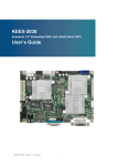
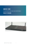
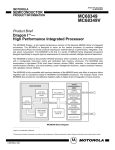
MOTOROLA SEMICONDUCTOR USER’S MANUAL M68HC705SR3 PGMR March, 1994 M68HC705SR3 PROGRAMMER USER’S MANUAL First Edition MOTOROLA INC., 7/22/96 ALL Rights Reserved CONTENTS CHAPTER 1 1.1 1.2 M68HC705SR3 Programmer Board Layout ............................................................. 4 Installation ................................................................................................................. 6 CHAPTER 2 2.1 STAND-ALONE MODE (Single Device Programming) ....... 8 Programming Procedures ......................................................................................... 8 CHAPTER 3 3.1 INTRODUCTION .............................................................................. 4 STAND-ALONE MODE (Gang Programming) .................... 10 Programming Procedures ........................................................................................ 10 CHAPTER 4 4.1 4.2 SERIAL PROGRAMMING MODE ........................................ 12 Programming Procedures ...................................................................................... 12 Programming Commands ....................................................................................... 14 FIGURES 1.1 1.2 1.3 Programmer Board Layout ..................................................................................... 5 Typical Programmer Adaptor Board ...................................................................... 6 Serial Port Pin Assignment ..................................................................................... 7 3.1 Gang Programming Configuration ........................................................................ 10 4.1 Memory Mapping Between EPROM Buffer and MC68HC705SR3 ..........................13 TABLE 2.1 M68HC705SR3 PGMR Programming Mode ............................................................................................... 9 MOTOROLA 3 CHAPTER 1 INTRODUCTION This document provides general information, connections, installation instructions, operating instructions, and support information for the MC68HC705SR3 Programmer. The M68HC705SR3 programmer enables the user to program MC68HC705SR3 OTPROM or EPROM devices. The Programmer is designed to support programming of four kinds of MCU packages via the use of M68HC705R3 programmer adaptor boards. The programmer supports programming of 40-pin DIP, 42-pin SDIP, 44-pin PLCC and 44-pin QFP MCU packages. The M68HC705SR3 programmer can be configured to program MCU devices by either of the two operating modes : STAND-ALONE programming mode and SERIAL programming mode. In stand-alone programming mode, user target code contained in an external EPROM is copied into the internal EPROM areas of the MCU device. Under stand-alone configuration, the M68HC705R3 programmer board can be cascaded together to perform gang programming operation. In serial programming mode, the target MCU EPROM areas can be programmed via the serial communication port equipped on the programmer board. Gang programming operation is not available in serial programming mode. 1.1 PROGRAMMER BOARD LAYOUT Figure 1.1 shows the simplified layout of the programmer board. For illustration purpose, only the necessary component locations are identified. Each MCU OTPROM or EPROM device is equipped with a built-in bootloader program contained in its mask ROM area between $0100 to $01FF and $1FFF to 1EDF. The MCU bootloader program together with the programmer circuitry enable the user to configure the programmer board to perform six modes of operations. The rotary switch SW1 determines the operating mode of the programmer board. Switch SW2 is the power supply switch. Since the M68HC705SR3 programmer is designed with an emphasis on ease of use and consequently has as few controls as possible. In either stand-alone or serial programming modes only two switches need to be operated : SW1 and SW2. When power is connected to the programmer board, controlled by switch SW2, the switch SW1 setting will be scanned and the required operation will then be performed automatically. The M68HC705SR3 programmer board supports programming of four kinds of MCU package types. Figure 1.2 shows the general layout of a programmer adaptor board. To program MCU of a particular package, fit together programmer adaptor board via connectors P1 & P2 and programmer board P3 & P4. MOTOROLA 4 M68HC705SR3 PGMR Connector P1 is for +5 Volts d.c. external power supply. Connector P7 is for RS-232 communication with the host computer. Connectors P5 and P6 are for cascading with others M68HC705SR3 programmer boards for gang programming. U8 is the location of the external EPROM socket. Gang Programming Input Connector Gang Programming Output Connector SW1 P7 Serial Port Connector P5 P6 Adaptor Board Connectors Eprom Socket Power Connector P1 SW2 Power Programmer Mode Select U8 P3 P4 Figure 1.1 Programmer Board Layout M68HC705SR3 PGMR MOTOROLA 5 Programmer Board Connectors U1 MCU P1 Programming Socket P2 Figure 1.2 Typical Programmer Adaptor Board Layout 1.2 INSTALLATION Installation of the M68HC705SR3 programmer board consists of connecting M68HC705SR3 programmer adaptor board to the programmer board, connecting a +5V external power supply to P1, connecting a host computer to the programmer board via connector P7 for serial programming, copying software to the host computer and cascading other M68HC705SR3 programmer boards for gang programming. MOTOROLA 6 M68HC705SR3 PGMR Adaptor Board Connection : Insert the required M68HC705SR3 programmer adaptor board onto the M68HC705SR3 programmer such that connectors P1 and P2 of the adaptor board are inserted into the connectors P3 and P4 of the M68HC705SR3 programmer board respectively. Power Connection : Connect a +5 Volts d.c. power supply to connector P1 contact labelled +5V, and connector P1 connector labelled GND is for ground connection. Serial Communications Connection : Serial RS-232 connection to a PC host computer requires a user supplied cable with one end of the cable fitted with a male DB25 connector. This DB25 male connector should be plugged into the M68HC705SR3 programmer connector P7. Figure 1.3 shows the P7 connector pin assignments. The other end of the cable needs the appropriate connector for the serial communications port of the PC host computer. This connection is only required for serial programming mode. Copying Software : Copy the files contained on the SR3SPROG diskette onto the PC host computer hard drive or onto an execution diskette. Install ANSI.SYS to your MS-DOS CONFIG.SYS file (e.g. DEVICE=ANSI.SYS ) and reboot your system. This process is only required for serial programming mode. Gang Programming Connection : M68HC705R3 programmer board can be cascaded together for gang programming using the supplied cascade cable. Connect one end of this cable to connector P6 of the source programmer board and the other end to connector P5 of the next programmer board. Same connections should be carried out to connect more programmers together. GND 1 TXD 2 RXD 3 NC 4 CTS 5 DSR 6 SIG-GND 7 DCD 8 NC 9 NC 10 NC 11 NC 12 NC 13 14 15 16 17 18 19 20 NC NC NC NC NC NC DTR 21 22 23 24 25 NC NC NC NC NC Figure 1.3 Serial Port Pin Assignment M68HC705SR3 PGMR MOTOROLA 7 CHAPTER 2 STAND-ALONE MODE (SINGLE DEVICE PROGRAMMING) Stand-alone programming mode enables programming of the MCU internal EPROM areas directly from an external 27C64 EPROM. The 27C64 external EPROM should contain the data to be programmed with the same addresses as the 3857 byte (MOR, User ROM and User Vectors) internal EPROM or ROM areas of the M68HC705R3 and the external EPROM should only have data at $0FFF and between addresses $1000 to $1EFF and $1FF0 to $1FFF inclusive. When programming MC68HC705SR3 MCU devices, locations of the external EPROM not in the internal EPROM or ROM address range are omitted, as are locations containing the data $FF, thus speeding up the programming operation. During the programming operation the STATUS LED flashes to indicate normal programming operation. After the programming operation has been completed, the contents of the MCU are verified against the external EPROM. Any failure to verify will result in illumination of the ERROR LED. Successful verification will result in illumination of the VERIFY LED. 2.1 PROGRAMMING PROCEDURES To program a MC68HC705SR3 MCU device, perform the following steps : 1. Make sure the power switch SW2 is OFF 2. Carry out the necessary installation as described in Section 1.2. 3. Install the target OTP or EPROM MCU into the socket at location U1 of the Programer Adaptor Board. CAUTION For PLCC package, the MCU device should be inserted into the socket UPSIDEDOWN. 4. Install the prepared external 27C64 EPROM into the socket at location U8 of the programmer board. 5. (This step is OPTIONAL) Turn the rotary switch SW1 to position 4 to select the blank check operation, refer to Table 2.1 for mode selection. Switch the power switch SW2 to ON position to begin blank check operation. During blank checking, the STATUS LED will flash. If the MCU device is not blank, the ERROR LED will lit. Alternatively, a blank device will result in illumination of the VERIFY LED. MOTOROLA 8 M68HC705SR3 PGMR 6. Turn the rotary switch SW1 to position either 0, 1 or 2 to select the appropriate programming and verification operation, refer to Table 2.1 for mode selection. 7. Switch the power switch SW2 to ON position to begin programming. During programming, the STATUS LED will flash. If programming and verification fail the ERROR LED will turn on. Successful programming and verification will result in illumination of the VERIFY LED. 8. Switch the power switch SW2 to OFF position and remove MCU device from the programmer adaptor board. To program additional MCUs, repeat step 1 to 7. SW1 POSITION ( MODE ) MODE FUNCTION 0 PROG - Program MCU EPROM ( Stand-alone ) 1 PROG MOR - Program MCU MOR ( Stand-alone ) 2 PROG ALL - Program MCU EPROM and MOR ( Stand-alone ) 3 VERF - Verify MCU EPROM ( Stand-alone ) 4 BLANK_CHK - Blank check MCU EPROM ( Stand-alone ) 5 UNUSED 6 LOAD RAM - Load and execute program in MCU RAM ( Serial Programming Mode) Table 2.1 Programming Mode M68HC705SR3 PGMR MOTOROLA 9 CHAPTER 3 STAND-ALONE MODE (GANG PROGRAMMING) Under stand-alone programming mode M68HC705SR3 programmer boards can be cascaded together to provide gang programming operation, that is programming several OTP or EPROM MCU devices simultaneously. Figure 3.1 illustrates the gang programming configuration. Programmer boards are connected together by the supplied cascading cables. Power supply voltage, target code and mode control signals are connected via these cables sourcing from the master programmer board. Since programming and verification processes are synchronized processes, only one external 27C64 target code EPROM is needed for the master programmer board. The mode select switch SW1 and the external EPROM of the other slave programmer boards are ignored. Master Board Slave Board (with EPROM ) ( No EPROM ) P6 P5 P6 Slave Board ( No EPROM ) P5 Slave Board ( No EPROM ) P6 P5 SW1 Cascade Cable External Power U8 SW2 Stand-Alone Mode Stand-Alone Mode Stand-Alone Mode Stand-Alone Mode Figure 3.1 Gang Programming Configuration 3.1 PROGRAMMING PROCEDURES Perform the following steps for gang programming operation : 1. Carry out the necessary installation procedures as described in Section 1.2. MOTOROLA 10 M68HC705SR3 PGMR 2. Switch the power supply switch SW2 of the master programmer board to OFF position follow by switching the power switches of the slave programmer boards to ON position. 3. Install target OTPROM or EPROM MCUs into the socket at location U1 of each Programmer Adaptor Board. CAUTION For PLCC package, the MCU device should be inserted into the socket UPSIDEDOWN. 4. Install the prepared external 27C64 EPROM into the socket at location U8 of the master programmer board. 5. (This step is OPTIONAL) Turn the rotary switch SW1 of the master programmer board to position 4 to select the blank check operation, refer to Table 2.1 for mode selection. Switch the power switch SW2 of the master programmer board to ON position to begin blank check operation. During blank checking, the STATUS LED on each programmer board will flash. If the corresponding MCU device is not blank, the corresponding ERROR LED will light. Alternatively, a blank device will result in illumination of the VERIFY LED. When blank check operation is completed, switch the power switch SW2 of the Master Programmer board to OFF position. 6. Turn the rotary switch SW1 of the master programmer board to position either 0, 1 or 2 to select the appropriate programming and verification operation, refer to Table 2.1 for mode selection. 7. Switch the power switch SW2 of the master programmer board to ON position to begin programming and verification. During programming, the STATUS LED will flash. If programming and verification fail the ERROR LED will light. Successful programming and verification will result in illumination of the VERIFY LED. 8. Switch the power switch SW2 of the master programmer board to OFF position and remove MCU devices from Programmer Adaptor boards. To program additional batch of MCUs, repeat from step 1 to 8. M68HC705SR3 PGMR MOTOROLA 11 CHAPTER 4 SERIAL PROGRAMMING MODE (SINGLE DEVICE) Serial programming mode enables the user to program and read the MCU EPROM areas via the serial port equipped on the programmer board. Programming operation consists of downloading user code from a host computer, programming user code onto the M68HC705SR3 MCU EPROM or OTPROM, and reading the code back from the programmed locations for verification using routines preloaded in the MCU RAM. The preloading of operating routines into the MCU RAM are carried out automatically by the serial programming interface program : SR3SPROG.EXE. Serial programming mode is accomplished by selecting the programmer LOAD RAM mode operation. The programmer LOAD RAM mode is selected by turning SW1 of the programmer board to position 6. A program called SR3SPROG.EXE is available for the IBM PC and similar machine that communicates with the programmer board serial connector via a RS232 link. The SR3SPROG.EXE program facilitates user interface, downloads operating routines onto the MCU RAM to enable the MCU to carry out programming or other operations by itself, downloads user code for programming, and receives user code from the programmed MCU for verification and visual display. In addition to normal programming operations, a number of data (user code) manipulation functions are also provided by the serial programming interface program. The SR3SPROG.EXE is a menu driven interface program. Upon execution, an EPROM Buffer, which imitates the actual MCU EPROM or OPTROM areas (see Figure 4.1) is created in the Host computer. User can select the appropriate operations, from the on screen menu, to perform different operations with the buffer. Refer to later sections for detail descriptions of individual on screen command. 4.1 PROGRAMMING PROCEDURES For serial programming, perform the following steps : 1. Carry out the necessary installation as described in section 2.1. 2. Make sure the power switch SW2 of the programmer board is OFF. 3. Set the rotary switch SW1 of the programmer board to position 6 to select the LOAD RAM programming mode. 4. Run the serial programming interface program by typing SR3SPROG <CR> at DOS prompt. 5. Install the target OTPROM or EPROM MCU into the socket at location U1 of the programmer adaptor board. CAUTION For PLCC package, the MCU device should be inserted into the socket UPSIDE DOWN. MOTOROLA 12 M68HC705SR3 PGMR SPIDER SR3 Memory Map I/O INTERNAL REGISTERS HOST EPROM Buffer RAM 0-2 Reserved MOR $0FFF $1000 USER EPROM $1EFF 7704-7705 Bootloader Program $1FF4 VECTORS $1FFF Figure 4.1 Memory Mapping Between EPROM Buffer and SR3 M68HC705SR3 PGMR MOTOROLA 13 6. Switch the power switch SW2 to ON position. 7. Program or verify the target MCU by selecting appropriate commands from the on screen menu. A command can be selected by using the UP and DOWN arrow keys and executed by pressing <CR>. Explanations of all the individual commands are given in the following section. 8. When all the operations have been completed, switch the power switch SW2 OFF and remove the programmed MCU device. 9. To program additional MCUs, repeat step 2 to 8. 4.2 PROGRAMMING COMMANDS This section provides individual explanations of the on screen user selectable commands of the serial programming interface program. Specify Serial Port For Communication : This command allows the user to specify the serial communication port of the host computer, the default is COM1. Upon execution of this command, the selected host computer serial port will be initialized. Serial communication routines will also be down loaded onto RAM of the programmer resident MCU (also the programming target MCU). When initialization is completed, control will be returned back to the user. Fill EPROM Buffer : Fill the entire Host computer EPROM Buffer with either $FF (the erase state) or $00 values. When this command is selected, the user will be asked to choose $FF or $00. The default EPROM buffer value is $FF. Blank Check User ROM and User Vector areas : When this command is selected the MCU Blank Check operating routine will be downloaded into the MCU RAM for execution. This Blank Check routine scans the User ROM and User Vector areas and returns a status code to the host computer to indicate the blank check status. When this operation is completed the MCU Blank Check routine returns control back to the MCU Bootloader program and waits for the next operating program to be downloaded from the host computer. UpLoad HOST Buffer From MCU (EPROM And VECTORS) : When this command is selected the MCU Upload To Host routine will be downloaded to the MCU RAM for execution. During execution the MCU reads its EPROM areas (from $0FFF to $1EFF and $1FF4 to $1FFF) and sends the content of each location to the host via the serial link. The host interface program receives the MCU EPROM contents and store them onto the host computer EPROM buffer for later operations. When this process is completed the MCU Upload To Host routine will return control back to the Bootloader program. During processing the interface program will notify/update the user by displaying messages on the screen and when the process is completed, control will be returned back to the user. MOTOROLA 14 M68HC705SR3 PGMR Load HOST Buffer with User Code : When this command is selected, user will be asked to enter a file name. The file given by the user should contain target MCU EPROM code in Motorola S19 format. If the given file contains valid data/format, its contents will be loaded into the Host EPROM Buffer. When this process is completed the interface program will return control back to the user. View/Edit HOST Buffer (EPROM and VECTORS) : This command will activate the EPROM Buffer Editor. The EPROM Buffer Editor allows the user to view and edit the EPROM Buffer (imitating the actual EPROM areas of the target MCU) values currently stored in the host computer in an interactive manner. Program/Verify MCU EPROM And VECTOR Locations Only : When this command is executed the MCU Program Eprom routine will first be downloaded onto the MCU RAM. Upon execution the host computer reads data from its EPROM Buffer and downloads data, byte by byte, to the programmer board, and the MCU will receive the data and program it into the next User EPROM location. The programmed location is then immediately read back by the MCU itself for verification. As in standalone programming mode, bytes to be programmed with $FF are skipped, thus reducing the overall programming time and allowing verification to be performed. If verification failed during processing, the whole operation will be terminated immediately. Programmer and Host controls will then be released back to the Bootloader and User respectively. Edit/Program/Verify The MASK OPTION REGISTER (MOR) : Similar to ‘Program/Verify User ROM areas except that MOR location is being worked on. Upon execution, the current MOR EPROM Buffer content (for MOR location only) will be displayed and the user will be asked to enter a new MOR value for the target MCU. As soon as the MOR Buffer has been updated the target MCU MOR location will be programmed and verified. User will then be notified of the program/verify result before controls are released back to Bootloader program and user. Verify MCU EPROM With HOST Buffer (EPROM/VECTORS) : When this command is executed, the contents of the Host EPROM Buffer will be compared with the contents of the actual MCU EPROM and VECTOR areas. The Dump MCU EPROM routine preloaded onto the MCU RAM reads and sends the contents of each EPROM and VECTOR location to the host. The Host receives the data and compares them with the corresponding value in the EPROM Buffer. The host will report the first location which fails the comparison and terminate the process immediately. Programmer and Host controls will then be returned back to the Bootloader and User respectively. Save Host Buffer To A File (In Motorola S19 Format) : This command will allow the user to save the contents of the Host EPROM Buffer to a file in Motorola S19 format. The user will have a choice of saving the entire EPROM Buffer (regardless of the contents including $FF value) or Non-$FF locations only. Exit : Quit the Serial programming host control program. M68HC705SR3 PGMR MOTOROLA 15 All products are sold on Motorola’s Terms & Conditions of Supply. In ordering a product covered by this document the Customer agrees to be bound by those Terms & Conditions and nothing contained in this document constitutes or forms part of a contract (with the exception of the contents of this Notice). A copy of Motorola’s Terms & Conditions of Supply is available on request. Motorola reserves the right to make changes without further notice to any products herein. Motorola makes no warranty, representation or guarantee regarding the suitability of its products for any particular purpose, nor does Motorola assume any liability arising out of the application or use of any product or circuit, and specifically disclaims any and all liability, including without limitation consequential or incidental damages. “Typical” parameters can and do vary in different applications. All operating parameters, including “Typicals”, must be validated for each customer application by customer’s technical experts. Motorola does not convey any license under its patent rights nor the rights of others. Motorola products are not designed, intended, or authorized for use as components in systems intended for surgical implant into the body, or other applications intended to support or sustain life, or for any other application in which the failure of the Motorola product could create a situation where personal injury or death may occur. Should Buyer purchase or use Motorola products for any such unintended or unauthorized application, Buyer shall indemnify and hold Motorola and its officers, employees, subsidiaries, affiliates, and distributors harmless against all claims, costs, damages, and expenses, and reasonable attorney fees arising out of, directly or indirectly, any claim of personal injury or death associated with such unintended or unauthorized use, even if such claim alleges that Motorola was negligent regarding the design or manufacture of the part. Motorola and !are registered trademarks of Motorola, Inc. Motorola, Inc. is an Equal Opportunity/Affirmative Action Employer. The Customer should ensure that it has the most up to date version of the document by contacting its local Motorola office. This document supersedes any earlier documentation relating to the products referred to herein. The information contained in this document is current at the date of publication. It may subsequently be updated, revised or withdrawn. Literature Distribution Centres: EUROPE: Motorola Ltd., European Literature Centre, 88 Tanners Drive, Blakelands, Milton Keynes, MK14 5BP, England, U.K. ASIA PACIFIC: Motorola Semiconductors (H.K.) Ltd., Silicon Harbour Center, No. 2, Dai King Street, Tai Po Industrial Estate, Tai Po, N.T., Hong Kong. JAPAN: Nippon Motorola Ltd., 4-32-1, Nishi-Gotanda, Shinagawa-ku, Tokyo 141, Japan. USA: Motorola Literature Distribution, P.O. Box 20912, Phoenix, Arizona 85036, U.S.A. M68HC705SR3 PGMR