1
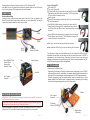
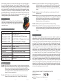
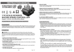
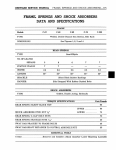
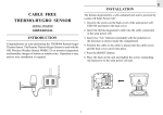
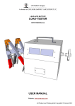
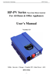
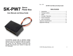
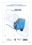
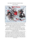
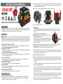
INSTRUCTION MANUAL
For best results clean the bottom of the speed control and chassis. Peel off the cover on one
side of the doubled-sided tape, and stick to the bottom of the speed control. Peel off other
side and stick the ESC to the chassis.
You may use the mounting plate(included) to fix the ESC to the chassis.
53mm
45.4mm
120
DAYS
14
+Yr
BRUSHLESS ESC FOR SHORT COURSE
Use a small piece of double-sided tape on the ON/OFF switch.
INTRODUCTION
Congratulations and thank you for purchasing TORO, Short Course(SC), high performance
brushless motor electronic speed control. The TORO SC,brushless ESC represents a latest
technologies, providing all the features and robust design qualities.
SAFETY NOTE
WARNING: This is an extremely powerful brushless motor system. We strongly
recommend removing your pinion gear for your own safety and the safety of those around you
before performing calibration and programming functions with this system. Please keep your
hands, hair, cloth, clear from the gear train and wheels of an armed high performance system.
WATER & ELECTRONICS DON'T MIX!
Never allow water, moisture, or other foreign materials to get inside ESC, motor, or on the
PC Boards. Water damage will void the warranty!
NO REVERSE VOLTAGE!
Reverse battery polarity can damage ESC & void warranty. Disconnect battery immediately
if a reverse connection occurs.
DISCONNECT BATTERIES WHEN NOT IN USE
Always disconnect the battery pack from the speed control when not in use to avoid short
circuits and possible fire hazard.
2 - 4 LI-PO CELLS ONLY
Never use fewer than 2 or more than 4 LIPO cells in the vehicle's main battery pack. The
TORO SC handles up to 4S LIPO input (16.8 Volts MAX).
TRANSMITTER ON FIRST
Turn on the transmitter first THEN turn on the speed control.
INSULATE WIRES
Always insulate exposed wiring with heat shrink tubing or electrical tape to prevent short
circuits, which can damage ESC.
SHORT COURSE OR SMALLER
The TORO SC is intended for4x4 Short Course or Smaller.
BEFORE YOU BEGIN
1)Plan Speed Control Placement
Choose a location for the speed control that is protected from debris. To prevent radio
interference place the speed control as far away from the radio receiver as possible
and keep the power wires as short as possible.
1/8
Ver. 1.1
2) Soldering
TIPS & TRICKS: Place the speed control upright and use double sided tape to secure it
to the bench. Doing so provides a stable work area and allows easy access to the solder
posts.
Attaching Wires to the Speed Control:
Red wires are usually used to connect the speed control to
the positive battery terminal.
Black wire is typically used for the battery negative terminal.
Inspect the housing on the speed control next to each post
or refer to the diagrams to determine which color wire to
attach to each post.
Strip back the insulation of the wire by about 2.4mm to 3.2mm (3/32" to 1/8") and "pre-tin"
the wire by heating the end and applying solder until it is thoroughly covered.
CAUTION: Be very careful not to splash yourself with hot solder.
Place the tip of the iron in the notch on top of the post and apply a small amount of solder to
the post. When the solder has flowed, remove the soldering iron, wipe the tip clean and
apply a small amount of fresh solder to it.
Pre-Heat both the wire and the post.
Hold the wire so the tinned end is in contact with the notch of the post. Now touch the iron
tip to the wire and the post. Wait about 4 seconds for the solder to flow, and then remove the
iron while still holding the wire. You may let go of the wire after a second or two when the
solder sets.
Same techniques described in the preceding section may be used to solder the wires to the
battery or to battery connectors.
IMPORTANT: Take precautions if removing factory battery connectors. Connecting the
battery backwards will cause damage, and will void warranty. When soldering connectors to
a battery pack, cut only one wire of the battery pack at a time to ensure that the exposed
wires cannot short together.
HINT: If you are using connectors for both the battery and the motor, make sure that they
are not the same or that you have a male and a female attached to the speed control wires.
That way, you cannot accidentally connect the battery to the motor wires or vice versa.
Make sure that the connector ends will be mated together correctly, male to female, and that
the wire colors match red to red and black to black.
2/8
Ver. 1.1
Prolonged/excessive heating of solder post (motor or ESC) will damage PCB.
Note: Make sure no wire strands have strayed to an adjacent solder post, this will result in
short-circuiting & severe ESC damage, which will void the warranty.
CONNECTIONS
Brushless Motor Wiring
Connect the blue, yellow and orange motor wires to the motor. There is no polarity on the
three ESC-to-motor wires, so do not worry about how you connect them initially. You may find
it necessary to swap two wires if the motor runs in reverse.
How to Calibrate ESC
ESC switch OFF.
Turn on the Transmitter.
Hold full throttle on your transmitter and turn the ESC's switch ON.
Keep holding full throttle on the transmitter. The ESC will flashes
LED and ring the initialization tones.
Wait 2 seconds
Green LED blinks rapidly and the motor will rings 1 second indicating
full throttle measured.
Red LED blinks whiles beeping, indicating it's time to push full
brake. Move throttle trigger to full brake and wait few seconds,
the ESC will blink red LED and rings 1 second indicating full brake
measure.
To Batt -
To Batt +
Switch
On/Off
Status LED(Multi Color)
Forward: Green
Reverse: Red
Stand By: Orange
Fan
To Receiver
Channel 2 (Throttle)
Orange LED blinks whiles beeping, indicating it's time for neutral.
Relax trigger to neutral (center). The ESC flash the orange LED
rapidly to accept the neutral position.
ESC rings 1 second indicating neutral position measure.
After calibration ESC will rings 1 second indicating that it is armed.
From this point on, when you connect batteries and turn on the switch, the ESC will give the
initialization tone and flash, and the arming tone will ring second or two later. If the ESC is
programmed for the Auto-Lipo setting, it will beep the number of cells in you Lipo pack
between the initialization tones and the arming tones. After the arming tone plays, the ESC
will ACTIVE and will respond to the throttle application.
Power Capacitor
ESC PROGRAMMING
Heat Sink
Fan / Program
Connector
1)Programming Card(Optional Part)
Programming Card allows you to modify the most commonly used settings in your TORO SC
controller all at the touch of a single button. No computer needed. Simply disconnect the Fan
lead from ESC and connect program lead form program card to ESC’s program connector.
Power the programming card as described below. Press and release button to move
between settings. Press and hold button to change the value for that setting. All the settings
will show on the programming card at once. Can't get any easier!
Battery
ESC/TRANSMITER CALIBRATION
IMPORTANT NOTE: Calibration is necessary for the first use of the ESC, or whenever
used with a new/different transmitter.
For users with a Futaba Transmitter, you must reverse the throttle channel signal on
your transmitter. Please refer to your Futaba instructions.
Individual transmitter's signals for full throttle, full brake and neutral vary. You must
calibrate your ESC so that it will operate more effectively with you transmitter.
3/8
Ver. 1.1
Fan / Program
Connector
To Receiver
Channel 2 (Throttle)
Program Lead
(Servo wire)
4/8
Ver. 1.1
2)Manual Programming
Manual Programming TORO SC is as simple as answering a few questions. The
TORO SC asks questing by beeping a setting number, followed by the possible
setting values. There are nine settings that can be programmed in the TORO SC.
Programmable Features
Question (Setting)
1)Reverse Lockout(D)*
2)Normal(D)*
Motor Direction
1) Normal(D)*
This is default motor rotation direction
2)Reverse
Opposite default motor rotation direction
2)50%(D)*
Note: Factory Defaults are indicated by asterisk (D)*
You must answer "yes" or "no" to the setting values as they are presented by TORO SC.
When you enter programming mode the ESC will emit a sequence of beeps and LED flashes
that tell you which programming step you are in. There are two parts to the beep sequence.
The first set of beeps indicates the 'Setting Number (Question), e.g. Brake/Reverse Type, and
the second set of beeps indicates a Setting Value, e.g. Reverse Lockout. Answering "No" to a
Setting value will cause the ESC to ask for the next value in that section. After a "Yes" answer
is accepted, the ESC knows you aren't interested in any other option in that section, so it
skips to the first option in the next section.
2)50%(D)*
Note: If you answer "no" to all Setting Values for a particular Setting Number, the ESC will
keep whatever value had been previously programmed. Only by answering "Yes" to a Setting
Value will the ESC store/change that value.
5)Disable(D)*
1)Disable(D)*
How to Enter Programming Mode
Plug Battery into the TORO SC
Hold full throttle on your transmitter
Turn the ESC switch ON
TORO SC flashes LED and rings once
Wait few seconds.
TORO SC flashes LED and rings 1 second indicating that it is ready for CALIBRATION mode
Continue to hold full throttle
TORO SC flashes LED while beeping
Wait another few seconds
TORO SC flashes LED and rings 1 second
TORO SC flashes LED while beeping indication that you are in PROGRAMMING mode
Let trigger go neutral (Centre)
1)Large
2)Normal(D)*
3)Small
4)Very Small
5)Smallest
At this point the TORO SC will be flashing/beeping the following sequence:
Beep-Pause-Beep... and then repeats
This indicates that you are at Question 1 and it is asking to accept/reject value 1.
2)Auto-Lipo(D)*
5/8
Ver. 1.1
6/8
Ver. 1.1
When answering a question, you will need to move the trigger to yes (full throttle) position or
the no (full brake) position and keep it there for about 3 seconds. When the ESC has
accepted your answer it will confirm your reply by flashing the LED and emitting a beeping
tone. Release the trigger allowing it to go to Neutral to confirm that you are ready for ESC to
ask you next question. You are not required to continue through all nine programming options.
For example, if you wish only to change the Brake/Reverse Type (Option 1) then after
programming that setting you can disconnect power from the ESC and you're ready to run.
Disconnecting the controller in the middle of programming simply retains the values for the
remaining programming options that were previously set up.
FAN REPLACEMENT
The TORO SC comes with a 30mm x 30mm x 10mm 5V Brushless fan.
Should the fan need replacement, simply unplug the fans power wire
from the TORO SC, remove the 4 screws that secure the fan and
remove the fan cover.
Solution: Try moving the throttle trim one way, then the other (usually towards the
throttle side is best). If your transmitter has a 50/50 and 70/30 setting for the
throttle, set it for 50/50 and retry calibration. Also, if you have changed the
dead band to a narrower band you may want to try going back to the "normal"
setting.
Problem: My vehicle acts like it has " turbo lag " (poor acceleration/punch for the first
few feet or yards)
Solution: Make sure you're using high quality batteries and a battery connector capable
of high amp flow (40-100 amps). This behavior is very typical of a battery pack
that is having difficulty providing the power your vehicle/system requires for
top performance. Use copper bars to connect cells rather than welded tabs.
Copper bars have a much lower resistance.
Problem: My battery pack is plugged into the ESC and nothing is working
Solution: Make sure the ESC's receiver plug is plugged into channel 2 on the receiver,
and that it's plugged in with the correct orientation. Double check your solder
connections on the battery plug, and make sure the battery is showing good
voltage.
SPEED CONTROL SPECIFICATION
Controls, TORO SC
Rev/Brk/Brk or Fwd/Fwd
Motor Limits,TORO SC
Input Power (Cells)
PRODUCT WARRANTY
Brushless KV ≤ 6000
Up to 2S(8.4Volt), ideal for 1/10 short course
Brushless KV ≤ 4000
Up to 3S(12.6Volt), for 1/10 buggies and short course
Brushless KV ≤ 3000
Up to 4S(16.8Volt), ideal for 1/8 buggies
On Resistance,Brushless
0.0004 Ohms per phase at 25℃(77℉)Trans.Temp
Continuous /Burst Current
120Amp / 760Amp
Switching BEC
6V 5Amp
Status LED
1 with 3 color (Red, Green & Orange)
Thermal Overload Protection
Yes
Dimensions(LxWxH)
55x37.6x38.4mm (2.17x1.47x1.51in)
Weight (Without wires)
87g (3.07oz)
The TORO SC Brushless ESC is guaranteed to be free from defects in materials or
workmanship for a period of 120 days from the original date of purchase (verified by dated,
itemized sales receipt). Warranty does not cover incorrect installation, components worn by
use, damage to case or exposed circuit boards, damage due to timing, damage from using
more than 4S Li-Po cells input voltage, cross-connection of battery/motor power wires,
overheating solder tabs, reverse voltage application, improper use or installation of external
BEC, damage resulting from thermal overload or short-circuiting motor, damage from incorrect
installation of FET servo or receiver battery pack, tampering with internal electronics, allowing
water, moisture, or any other foreign material to enter ESC or get onto the PC board, incorrect
installation/wiring of input plug plastic, allowing exposed wiring or solder tabs to short-circuit,
or any damage caused by a crash, flooding or natural disaster. Because SKYRC has no
control over the connection & use of the speed control or other related electronics, no liability
may be assumed nor will be accepted for any damage resulting from the use of this product.
Every SKYRC speed control & motor is thoroughly tested & cycled before leaving our facility
and is, therefore, considered operational. By the act of connecting/operating speed control,
user accepts all resulting liability. In no case shall our liability exceed the product's original
cost. We reserve the right to modify warranty provisions without notice. This product is not
intended for use by children under 14 years of age without the strict supervision of an adult.
Use of this product in an uncontrolled manner may result in physical damage or injurise take
extra care when operating any remote control vehicle.
TROUBLE SHOOTING
Problem: My TORO ESC may or may not arm, but it will not calibrate to my transmitter
Solution: Most calibration issues can be solved by changing settings on the transmitter.
Make sure you have both your throttle and brake endpoints (called EPA or
ATV on your radio) on the throttle channel out to between 100 to 120%. Make
sure if you have a Futaba or Futaba made transmitter to have the throttle
channel set to the reversed position.
Problem: My ESC calibrates for the full throttle and full brake positions but won't
calibrate to the neutral throttle position. (Orange LED keeps flashing)
SPECIFICATIONS ARE SUBJECT TO CHANGE WITHOUT NOTICE.
Manufactured by
SKYRC TECHNOLOGY CO., LTD.
www.skyrc.com
2011 SkyRC Technology Co., Ltd. All Rights Reserved.
7504-0215-01
7/8
Ver. 1.1
8/8
Ver. 1.1