1
COAGULATION
ANALYZER
OPERATION MANUAL
Instrument manufactured by
Sigma Amelung,
Lemgo, Germany
REVISION DATE 10/23/01
SIGMA DIAGNOSTICS INSTRUMENT WARRANTY
Sigma-Aldrich Co., Inc. ("Sigma"), warrants that instruments it sells to be free from
defects in workmanship and materials during normal use by the original purchaser.
This Warranty shall continue for a period of one year from the date of invoice to the
original purchaser, or until title is transferred from the original purchaser, whichever
occurs first (the "Warranty Period").
If any defects occur during the Warranty Period, contact the Sigma Service Center
immediately, and be prepared to furnish pertinent details concerning the defect, the
model number, and the serial number.
Warranty service is provided 8:30 a.m. through 5:00 p.m., Monday through Friday,
except on Sigma observed holidays. Any service performed at other times, and all
service required to correct defects or malfunctions not covered by this Warranty, will be
billed on a time-and-material basis at Sigma's labor rates then in effect.
This Warranty does not cover defects or malfunctions which: (1) are not reported to
Sigma during the Warranty Period and within one week of occurrence; (2) result from
chemical decomposition or corrosion; (3) are described in the applicable Sigma
Operation Guide; (4) result from maintenance, repair, or modification performed
without Sigma's prior written authorization; or (5) result from misuse, abuse or
accident.
Sigma's liability for all matters arising from the supply, installation, use, repair, and
maintenance of the instrument, whether arising under this Warranty or otherwise, shall
be limited solely to the repair or (at Sigma's sole discretion) replacement of the
instrument or of components thereof. In no event shall Sigma be liable for injuries
sustained by third parties, incidental or consequential damages, or lost profits.
Replaced parts shall become the property of Sigma.
THE FOREGOING IS THE SOLE WARRANTY MADE BY SIGMA REGARDING THE
INSTRUMENT, AND SIGMA SPECIFICALLY DISCLAIMS ALL OTHER WARRANTIES,
EXPRESSED OR IMPLIED, INCLUDING THE WARRANTIES OF MERCHANTABILITY
AND OF FITNESS FOR A PARTICULAR PURPOSE.
KC4 ∆™ User Manual, October 2001
(Software Version 1.1B)
© 2001 Sigma-Aldrich Co.
October 2001
EN
KC4 ∆™
Table of Contents
1
2
3
4
0
INTRODUCTION.................................................................................................... 1-1
1.1
INTENDED USE ................................................................................................. 1-1
1.2
PRINCIPLES OF OPERATION.............................................................................. 1-1
1.3
PHYSICAL SPECIFICATIONS .............................................................................. 1-2
1.4
PERFORMANCE SPECIFICATIONS ..................................................................... 1-3
1.5
PHYSICAL DESCRIPTION ................................................................................... 1-6
1.6
FRONT VIEW (FIGURE 1) ................................................................................... 1-7
1.7
KEYPAD (FIGURE 2)........................................................................................... 1-8
1.8
BACK VIEW (FIGURE 3) ..................................................................................... 1-9
1.9
MULTIPETTE (FIGURE 4 A & B) ....................................................................... 1-10
1.10
BALL DISPENSER (FIGURE 5) .......................................................................... 1-11
1.11
THERMAL PRINTER (FIGURE 6) ....................................................................... 1-11
1.12
PRINTER OPTIONS ........................................................................................... 1-12
INSTALLATION ..................................................................................................... 2-1
2.1
UNPACKING ....................................................................................................... 2-1
2.2
KC4 ∆™ COAGULATION ANALYZER START-UP KIT ............................................ 2-1
2.3
LOCATION REQUIREMENTS .............................................................................. 2-2
2.4
ELECTRICAL REQUIREMENTS .......................................................................... 2-2
2.5
PRELIMINARY CHECK OF THE INSTRUMENT OPERATION ................................ 2-3
GENERAL OPERATION ......................................................................................... 3-1
3.1
INSTRUMENT PREPARATION ............................................................................. 3-1
3.2
TEMPERATURE INDICATOR SCREEN ................................................................ 3-1
3.3
MAIN MENU FUNCTIONS ................................................................................... 3-2
3.4
PASSWORD MODIFICATION .............................................................................. 3-2
3.5
PROGRAM MODIFICATION ................................................................................ 3-3
3.6
REAGENT HANDLING ........................................................................................ 3-4
3.7
CUVETTE PREPARATION ................................................................................... 3-4
3.8
SAMPLE PREPARATION ..................................................................................... 3-5
3.9
PIPETTING ......................................................................................................... 3-6
3.10
TO DISPENSE SAMPLE ...................................................................................... 3-7
3.11
TO DISPENSE FIRST REAGENT ......................................................................... 3-8
3.12
TO DISPENSE START REAGENT ........................................................................ 3-9
3.13
SELECTING A TEST TO BEGIN A RUN ............................................................. 3-10
3.14
PATIENT IDENTIFICATION ............................................................................... 3-11
3.15
TESTING .......................................................................................................... 3-11
3.16
MANUAL START PROCEDURE ......................................................................... 3-12
3.17
AUTOMATIC START PROCEDURE .................................................................... 3-12
3.18
PRINTING RESULTS ......................................................................................... 3-13
MODE PROGRAMMING ......................................................................................... 4-1
4.1
ROUTINE PROGRAMMING ................................................................................. 4-1
4.2
EMERGENCY PROGRAMMING ........................................................................... 4-2
4.3
INDIVIDUAL PROGRAMMING ............................................................................. 4-3
October 2001
TOC-1 EN
KC4 ∆™
0
5
Table of Contents
TEST PROGRAMMING........................................................................................... 5-1
5.1
INR .................................................................................................................... 5-1
5.2
INR FLOW CHART.............................................................................................. 5-3
5.3
PROTHROMBIN TIME (PERCENT ACTIVITY CURVE) .......................................... 5-4
5.4
PT (PERCENT ACTIVITY) FLOW CHART.............................................................. 5-7
5.5
RATIO FLOW CHART ......................................................................................... 5-8
5.6
ACTIVATED PARTIAL THROMBOPLASTIN TIME................................................. 5-9
5.7
APTT FLOW CHART ......................................................................................... 5-11
5.8
FIBRINOGEN ................................................................................................... 5-12
5.9
FIBRINOGEN FLOW CHART............................................................................. 5-15
5.10
FACTORS......................................................................................................... 5-16
5.11
FACTORS FLOW CHART .................................................................................. 5-19
5.12
STATS.............................................................................................................. 5-20
6
QUALITY CONTROL .............................................................................................. 6-1
7
MAINTENANCE ..................................................................................................... 7-1
8
TROUBLESHOOTING............................................................................................. 8-1
A
8.1
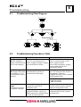
TROUBLESHOOTING FLOW DIAGRAM .............................................................. 8-1
8.2
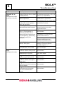
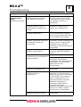
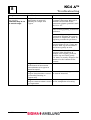
TROUBLESHOOTING PROCEDURES TABLE...................................................... 8-1
APPENDIX ............................................................................................................ A-1
A.1
INR FAST TRACK ............................................................................................... A-1
A.2
APTT FAST TRACK ............................................................................................. A-2
A.3
FIBRINOGEN FAST TRACK ................................................................................ A-3
A.4
FIBRINOGEN CALIBRATION CURVE DILUTION ................................................. A-4
A.5
EXTRINSIC FACTORS II, V, VII AND X FAST TRACK .......................................... A-5
A.6
EXTRINSIC FACTOR STANDARD CURVE DILUTIONS ........................................ A-6
A.7
INTRINSIC FACTORS VIII, IX, XI AND XII FAST TRACK ...................................... A-7
A.8
INTRINSIC FACTOR STANDARD CURVE DILUTIONS ......................................... A-8
TOC-2 EN
October 2001
KC4 ∆™
Introduction
1
1Introduction
Contents
1.1
INTENDED USE...................................................................................... 1-1
1.2
PRINCIPLES OF OPERATION.................................................................. 1-1
1.3
PHYSICAL SPECIFICATIONS .................................................................. 1-2
1.4
PERFORMANCE SPECIFICATIONS ......................................................... 1-3
1.5
PHYSICAL DESCRIPTION ....................................................................... 1-6
1.6
FRONT VIEW (FIGURE 1) ....................................................................... 1-7
1.7
KEYPAD (FIGURE 2)............................................................................... 1-8
1.8
BACK VIEW (FIGURE 3).......................................................................... 1-9
1.9
MULTIPETTE (FIGURE 4 A & B).............................................................1-10
1.10
BALL DISPENSER (FIGURE 5)............................................................... 1-11
1.11
THERMAL PRINTER (FIGURE 6)........................................................... 1-11
1.12
PRINTER OPTIONS ...............................................................................1-12
October 2001
1-0 EN
KC4 ∆™
Introduction
1.1
1
Intended Use
The KC4 ∆™ Coagulation Analyzer is a semi-automated mechanical clot detection
system designed for the determination of prothrombin times (PT), activated partial
thromboplastin times (APTT), fibrinogen concentrations determined by Clauss
methodology, and other clotting assays. Any clotting based assay, which has fibrin
formation as its endpoint may be performed on the KC4 ∆™ Coagulation Analyzer.
Measurement can be qualitative or quantitative. When used in conjunction with
appropriate reagents, the sample can be plasma, or whole blood.
The additions of both sample and reagents are manual. Time measurement of the
clotting endpoint is automated.
1.2
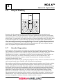
Principles of Operation
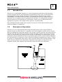
The KC4 ∆™ is an electromechanical clot detection system. The system utilizes a
special cuvette in which there is a stainless steel ball. Sample is added to the cuvette.
After an appropriate incubation period, the cuvette is placed into the measuring well of
the KC4 ∆™. The measuring well rotates slowly (50 rpm) causing the cuvette to rotate
along its longitudinal axis. Because the cuvette is positioned at a slight angle, gravity
and inertia always position the ball at the lowest point of the cuvette. Exactly opposite
the ball-position is a magnetic sensor. With the addition of appropriate reagent, a timer
is started. As coagulation takes place, fibrin strands form in the reaction mixture. The
fibrin strands pull the ball away from its position and triggers an impulse in the
magnetic sensor. This impulse electronically stops the timer (see diagrams).
October 2001
1-1 EN
KC4 ∆™
1
1.3
Introduction
Physical Specifications
Type:
Coagulation Analyzer, Bench Top
Online:
Unidirectional
Principle:
Ball Method
Measuring Channels:
4
Display:
LCD
Incubation Wells:
8
Reagent Wells:
5
Dimensions
Height:
12.0 cm
Width:
35.4 cm
Depth:
45.0 cm
Weight
6.3 kg
Power Supply
Voltage
110–220V/50–60 HZ
Power Consumption
1.5A at 100V; 0.4A at 220V
Temperature Control
Reagent Warming Wells:
37.0°C ± 0.5°C
Reaction Incubation Wells:
37.0°C ± 0.5°C
Measurement Wells:
37.0°C ± 0.5°C
Measurement Time
Minimum:
4.5 seconds
Maximum:
999.9 seconds
1-2 EN
October 2001
KC4 ∆™
1
Introduction
1.4
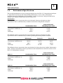
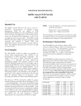
Performance Specifications
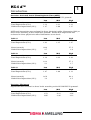
The overall performance of any testing performed on the KC4 ∆™ Coagulation Analyzer
is dependent not only on the instrument performance, but is also a function of
specimen integrity (collection and handling) as well as accuracy and precision of the
sample and reagent dispensing system being used.
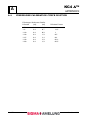
Correlation:
The following linear regression data was obtained during evaluation to show
equivalence with a commercially available mechanical coagulation analyzer.
Number of Samples
Correlation Coefficient (r)
Slope
Intercept
Prothrombin Time
121
0.998
1.051
–0.241
Activated Partial
Thromboplastin Time
110
0.896
1.235
0.873
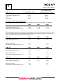
The following linear regression data was obtained during evaluation to show
equivalence with a commercially available photo-optical coagulation analyzer.
Number of Samples
Correlation Coefficient (r)
Slope
Intercept
Fibrinogen
109
0.930
1.067
30.749
Factor X
112
0.974
1.010
–0.166
Factor IX
101
0.897
0.958
3.403
The following linear regression data was obtained in three physician’s office laboratories
(POL) during evaluation to show equivalence with manufacturer derived results on the
KC4 ∆™ Coagulation Analyzer.
POL #1
Number of Samples
Correlation Coefficient (r)
Slope
Intercept
Prothrombin Time
47
0.991
0.981
0.492
Activated Partial
Thromboplastin Time
44
0.960
1.066
0.379
POL #2
Number of Samples
Correlation Coefficient (r)
Slope
Intercept
Prothrombin Time
45
0.989
1.019
–0.248
Activated Partial
Thromboplastin Time
46
0.965
1.029
1.021
October 2001
1-3 EN
KC4 ∆™
1
POL #3
Number of Samples
Correlation Coefficient (r)
Slope
Intercept
Introduction
Activated Partial
Thromboplastin Time
47
0.927
0.786
9.470
Prothrombin Time
52
0.974
1.012
0.326
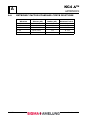
Precision: Prothrombin Time (PT)
Imprecision was evaluated at three levels according to the NCCLS EP5-T2 protocol.
Mean (seconds)
Total Imprecision (CV%)
Within-Run Imprecision (CV%)
Low
13.20
2.03
1.02
Mid
33.53
2.50
1.28
High
39.66
4.18
1.53
PT total imprecision was evaluated in three physician’s office laboratories (POL) at three
levels according to NCCLS EP10-T protocol. Within-Run imprecision was evaluated in
three physician’s office laboratories at two levels.
POL #1
Mean (seconds)
Total Imprecision (CV%)
Low
13.1
1.97
Mean (seconds)
Within-Run Imprecision (CV%)
12.7
1.3
POL #2
Mean (seconds)
Total Imprecision (CV%)
Low
12.1
2.59
Mean (seconds)
Within-Run Imprecision (CV%)
12.1
2.6
POL #3
Mean (seconds)
Total Imprecision (CV%)
Low
11.3
1.57
Mean (seconds)
Within-Run Imprecision (CV%)
11.4
2.0
1-4 EN
Mid
26.8
1.63
High
42.9
2.47
44.1
1.1
Mid
23.3
7.12
High
40.7
3.0
41.7
1.8
Mid
22.8
7.41
High
34.2
0.50
34.7
1.3
October 2001
KC4 ∆™
1
Introduction
Precision: Activated Partial Thromboplastin Time (APTT)
Imprecision was evaluated at three levels according to the EP5-T2 protocol.
Mean (seconds)
Total Imprecision (CV%)
Within-Run Imprecision (CV%)
Low
28.55
3.12
1.47
Mid
51.01
3.41
1.60
High
75.78
3.21
1.37
APTT total imprecision was evaluated in three physician’s office laboratories (POL) at
three levels according to NCCLS EP10-T protocol. Within-Run imprecision was
evaluated in three physician’s office laboratories at two levels.
POL #1
Mean (seconds)
Total Imprecision (CV%)
Low
29.0
2.83
Mean (seconds)
Within-Run Imprecision (CV%)
30.8
2.7
POL #2
Mean (seconds)
Total Imprecision (CV%)
Low
29.2
4.38
Mean (seconds)
Within-Run Imprecision (CV%)
28.2
2.1
POL #3
Mean (seconds)
Total Imprecision (CV%)
Low
30.0
1.87
Mean (seconds)
Within-Run Imprecision (CV%)
26.9
1.4
Mid
43.3
3.15
High
57.6
1.87
57.5
1.6
Mid
42.7
2.29
High
57.0
2.84
57.1
1.7
Mid
54.7
1.80
High
68.6
2.13
64.4
2.5
Precision: Fibrinogen
Imprecision was evaluated at three levels according to the NCCLS EP5-T2 protocol.
Mean (mg/dl)
Total Imprecision (CV%)
Within-Run Imprecision (CV%)
October 2001
Low
104.09
3.53
2.05
Mid
154.10
6.21
2.86
High
323.53
4.36
2.12
1-5 EN
KC4 ∆™
1
Introduction
Precision: Factor X
Imprecision was evaluated at three levels according to the NCCLS EP5-T2 protocol.
Mean (%)
Total Imprecision (CV%)
Within-Run Imprecision (CV%)
Low
31
8.28
2.63
Mid
57
5.71
2.22
High
102
5.22
2.20
Precision: Factor IX
Imprecision was evaluated at three levels according to the NCCLS EP5-T2 protocol.
Mean (%)
Total Imprecision (CV%)
Within-Run Imprecision (CV%)
1.5
Low
24
5.88
3.96
Mid
49
6.89
4.04
High
98
4.06
2.54
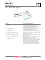
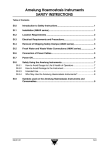
Physical Description
The external features of the KC4 ∆™ Coagulation Analyzer are shown in Figure 1
(Front), Figure 2 (Keypad), Figure 3 (Rear), Figure 4 (Automatic Multipette with starter
cable), Figure 5 (Ball Dispenser) and Figure 6 (Thermal Printer).
1-6 EN
October 2001
KC4 ∆™
1
Introduction
1.6
Front View (Figure 1)
1
3
4
1
5
6
2
7
Item
Function or Description
1. Rack
Used for transferring cuvettes from
preparation area to reaction incubation
wells and rotating test positions.
2. Preparation Area
Room temperature wells used for sample
preparation prior to incubation.
3. Pipette Tubes
Used to store the pipettes when not in use.
4. Reagent Warming Wells (5)
Three 15 mm, and two 11 mm heated wells
used to warm reagents.
5. Reaction Incubation Wells (8)
Heated wells used for incubation of sample
and first reagent.
6. Rotating Test Positions (4)
Positions where start reagent is added and
the clotting time is measured.
7.
Displays elapsed time in seconds during
incubation for each of 4 channels. Displays
elapsed time in seconds and tenths of
seconds during clot time measurement.
Displays incubation times, clotting times,
programming selections and other menus.
Display Screen
October 2001
1-7 EN
KC4 ∆™
1
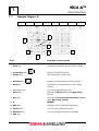
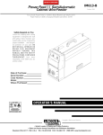
1.7
Introduction
Keypad (Figure 2)
2
1
2
3
4
4
4
4
5
12
6
11
7
10
9
8
Item
Function or Description
1. Start Key
Activates automatic measurement timer.
2. Incubation Key
Starts Incubation timers.
3. Ready Key
Not functional at this time.
4. Channel Key
Starts manual timing and incubation.
5. Stop Key
Terminates measurements, and aborts
testing.
6. Function Keys
Used in programming tests.
7. Menu Key
Returns to Main Menu from Operating
Screen.
8. Run Key
Returns to Test Program Selection Screen
from Operating Screen.
9. ↵
ENTER
10. ESC Key
Escapes back to previous function
11. Printer Key
Used to turn printer on or off
12. Dilution Key
Used to change the patient dilution.
13. DEL key
1-8 EN
October 2001
KC4 ∆™
1
Introduction
1.8
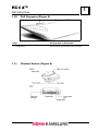
Back View (Figure 3)
3
3.
4.
2.
1.
Item
Function or Description
1. Thermal Printer Port
Thermal Printer connection.
2. Automatic Multipette Socket(s)
Used to connect pipettes (Remove the capplug in the Multipette).
3. Power Switch
Powers instrument off/on.
4. Power Supply Socket
Connects instrument to power cord.
October 2001
1-9 EN
KC4 ∆™
1
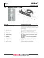
1.9
Introduction
Multipette (Figure 4 A & B)
4
Combitip
4-A
Multipette
4-B
Item 4-B
Function or Description
1. Volume selection dial
Determines pipetting volume: setting (1–5)
multiplied by the minimum pipetting
volume of the Combitip (1.25 ml or 2.50 ml
pipette tips).
2. Pipetting lever
The volume is pipetted by pressing the
pipetting lever down until it stops.
3. Filling lever
The Combitip is filled by sliding this lever
upward.
4. Locking clamp
The locking clamp serves to firmly clamp
the Combitip.
5. Combitip
The pipette tip used with the automatic
multipette.
6. Combitip Cone
Portion of the pipette tip that aspirates
reagent.
7. Starter Cable
Connects pipette to instrument.
1-10 EN
October 2001
KC4 ∆™
1
Introduction
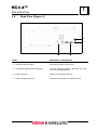
1.10
Ball Dispenser (Figure 5)
5
Item
Description or Function
1. Dispenser
For loading microballs into cuvettes
1.11
Thermal Printer (Figure 6)
6
October 2001
1-11 EN
KC4 ∆™
1
1.12
Introduction
Printer Options
From the Main Menu, press <↵>. Press the <PRINTER> key. The (*) shows which
options have been selected. If the analyzer is connected to a host LIS, ensure that
option 4 is selected. If the analyzer is not connected to a host LIS, select 5.
Print Test Page
1
Print Switch On
2*
Print Switch Off
3
Line - out incl. Error Val.
4*
Line - out excl. Error Val.
5
Press ENTER <↵> to continue
1-12 EN
October 2001
KC4 ∆™
Installation
2
2Installation
Contents
2.1
UNPACKING........................................................................................... 2-1
2.2
KC4 ∆™ COAGULATION ANALYZER START-UP KIT ................................ 2-1
2.3
LOCATION REQUIREMENTS................................................................... 2-2
2.4
ELECTRICAL REQUIREMENTS ............................................................... 2-2
2.5
PRELIMINARY CHECK OF THE INSTRUMENT OPERATION..................... 2-3
October 2001
2-0 EN
KC4 ∆™
2
Installation
2.1
Unpacking
The KC4 ∆™ Coagulation Analyzer is shipped in a transport box designed to protect the
instrument from damage during shipment. If damage is apparent, immediately notify
the shipping company. Note the damage on the shipping bill of lading and notify your
Sigma Diagnostics Sales Representative.
2.2
KC4 ∆™ Coagulation Analyzer Start-Up Kit
Carefully remove the instrument and accessories from the transport box. Check that
the following items have been included:
KC4 ∆™ Coagulation Analyzer
1. Power Cable
2. KC Micro Tetravettes
3. KC Delta Multipette with Starter Cable and Adapter Cord
4. Combitips (1.25 ml); 5 each
5. KC Pipette Tips, Yellow 200µl; 1 tray
6. Tubes, Plastic (14.5 x 85 mm); 100 each
7. Tubes, Glass (15 x 85 mm), 50 each
8. Power Supply 12V
9. Lead for Power Supply
10. Protective Dust Cover; 1 each
Optional Items
Catalog Number
Item
1. P2864
KC Series Printer with Power Adapter
2. K1638 *
KC Series Thermal Printer Paper
3. K4882
KC4 ∆™ Multipette with Starter Cable
4. K0508 *
KC4 ∆™ Combitips 1.25 ml
5. K1510 *
KC4 ∆™ Combitips 2.50 ml
6. K4257 *
KC Pipette Tips, Yellow, 200µl, 10 trays
7. T9304 *
Tubes, Glass (15 x 85 mm), 50 each
8. K4887 *
KC4 ∆™ Tetravettes
9. T2242*
Tubes, plastic (14.5 x 85 mm)
10. K1635*
KC Micro Cuvettes with Ball Dispencer
11. A6083
Coated Stir Bar
12. K6208
APTT Stir Bar
13. K0633
KC Pittette Tube Sleeves
October 2001
2-1 EN
KC4 ∆™
2
Installation
*These are consumable items and should be ordered as needed.
Pipettes are required for the test performance. Although the use of a Multipette will
ensure the start of the timing measurement is simultaneous with the addition of the
reagent, it is not mandatory.
Read the Operation Manual carefully prior to using the KC4 ∆™ Coagulation Analyzer.
The Operation Manual has been written to provide the most comprehensive
understanding of the operation of the KC4 ∆™ Coagulation Analyzer and to enable
you to fully utilize the features of the instrument.
2.3
Location Requirements
1. Place the KC4 ∆™ Coagulation Analyzer on a stable, vibration and dust free work
surface. It should not be positioned next to a centrifuge or other equipment, which
may cause vibration. The KC4 ∆™ Coagulation Analyzer should also be protected
from moisture.
2. To avoid exceeding the control range of the instrument, place the KC4 ∆™
Coagulation Analyzer in an area with a maximum room temperature of 30°C.
It should not be positioned in an area directly below ventilating ducts which
produce strong air currents. Do not expose the KC4 ∆™ Coagulation Analyzer
to direct sunlight. Sunlight influences the temperature control.
3. It is preferable to place the KC4 ∆™ Coagulation Analyzer in an area which is no
further than (6 ft.) 1.8 m from an electrical outlet. The instrument should not be
operated from an extension cord which does not employ protective grounding. The
electrical outlet used should not be shared with any devices, which consume large
amounts of power on a cyclic basis (e.g., centrifuges, air conditioners, and
refrigerators). When these type of devices cycle on and off, there may be a voltage
drop in the line which could interfere with the proper functioning of the instrument.
2.4
Electrical Requirements
The KC4 ∆™ Coagulation Analyzer is designed with a factory equipped three-pronged
grounding plug designed to be connected to the Power Supply, which is then plugged
into the analyzer. Under no circumstances should it be connected to an ungrounded
two-pronged receptacle. This procedure is in accordance with the National Electrical
Code and other applicable ordinances for this type of installation.
1. Do not use an extension cord which cannot to provide protective grounding.
2. It is recommended that any repair work other than routine maintenance
be performed by a trained specialist familiar with the hazards involved.
3. If safe operation of the KC4 ∆™ Coagulation Analyzer is no longer possible,
the instrument must be taken out of service.
2-2 EN
October 2001
KC4 ∆™
2
Installation
2.5
Preliminary Check of the Instrument Operation
The preliminary function checks of instrument operation should be performed prior to
using the instrument. This preliminary function check is to ensure that the instrument
is functioning properly prior to reporting patient results.
1. Connect the power cable to the power cable socket on the back of the
instrument (DC6.5V 2A).
2. Connect the Data Cable from the Serial Port on the Printer to the Printer port
on the back of the Analyzer if utilizing the KC4 ∆™ printer.
3. Activate the KC4 ∆™ Coagulation Analyzer by pressing the off/on switch
located on the left hand side of the back of the instrument.
4. Observe that the display screen lights up; a screen appears giving the operator
the option to select the operating language. After the language selection, a
screen showing a thermometer appears and will remain displayed while the
instrument warms up to 37°C.
5. Observe that four of the measurement wells are rotating. The wells will rotate
continuously whenever the instrument is on.
6. Place a KC4 ∆™ Micro cuvette or Tetravette into each position of the cuvette
rack. Place the cuvette rack on the rotating test positions such that the cuvettes
are sitting flush in the holes. If using a KC4 ∆™ Micro cuvette, dispense one
ball into each cuvette using the ball dispenser. Observe that the ball falls to the
front of the cuvette and stays there.
7. Verification of temperature can be performed by placing approximately 3 ml of
water into a 15-mm reagent tube. Place a thermometer into the tube and allow
to equilibrate until the temperature has stabilized. Approximately 15 minutes
will be required for temperature stabilization. The temperature should be
37° ± 0.5°C.
Note: The use of smaller diameter tubes is not recommended due to inadequate
heat transfer.
8. To verify the operation of the timers, use the pipette with the start cable, and
the measuring wells, a program modification is needed. From the Main Menu,
select 3 Program Selection.
9. Enter the password; default password is 1 2 3 4. Press <↵>.
10. Select 4 Individual Program Modify; press TZ (Thrombin Clotting Time) key.
Press <↵>.
11. To access the program settings, press <↵>. Press 2 (No) until “Test TZ” appears
at the top of the screen. Press 1 (Yes) to modify TZ.
12. Enter 1 (duplicate testing), and 10% for allowed CV; press <↵> to continue.
13. Enter incubation time of 10 seconds, press <↵>. Press 2 (No) when
modifications are done.
14. Press <↵> to continue. Press Run; select 3 Start Individual Program. Press TZ
(Thrombin Clotting Time) key; press <↵>.
October 2001
2-3 EN
KC4 ∆™
2
Installation
15. Enter 2 samples per rack; press <↵>. Press <↵> again to bring the Operating
Screen up.
16. If the automatic Multipette with the starter cable is being used, plug the pipette
cable connection into the pipette cable socket on the rear of the KC4 ∆™. Snap
the locking mechanism on the Multipette into place.
17. Start timers by pressing the <START> key
timers
, followed by the individual well
. When all timers are showing 0.0, press and hold the <START>
key
, while at the same time, depress the trigger switch on the Multipette 4
times. All wells should begin timing.
18. After at least 10 seconds, remove the cuvette rack from the rotating test
positions. Observe that the timers stop and are indicating the elapsed time in
seconds and tenths of seconds.
19. The first result will print automatically (if the optional printer has been
installed), or will appear on the screen. Press <↵> to print the second result,
and clear the memory.
With the completion of the Preliminary Checks of Instrument Operation, installation is
complete and the instrument is ready for operation. If the instrument fails to perform
any of the tests with the specifications listed, call Sigma Diagnostics Technical Service
for assistance.
2-4 EN
October 2001
KC4 ∆™
General Operation
3
3General Operation
Contents
3.1
INSTRUMENT PREPARATION ................................................................. 3-1
3.2
TEMPERATURE INDICATOR SCREEN..................................................... 3-1
3.3
MAIN MENU FUNCTIONS........................................................................ 3-2
3.4
PASSWORD MODIFICATION ................................................................... 3-2
3.5
PROGRAM MODIFICATION..................................................................... 3-3
3.6
REAGENT HANDLING............................................................................. 3-4
3.7
CUVETTE PREPARATION ....................................................................... 3-4
3.8
SAMPLE PREPARATION ......................................................................... 3-5
3.9
PIPETTING ............................................................................................ 3-6
3.10
TO DISPENSE SAMPLE........................................................................... 3-7
3.11
TO DISPENSE FIRST REAGENT.............................................................. 3-8
3.12
TO DISPENSE START REAGENT............................................................. 3-9
3.13
SELECTING A TEST TO BEGIN A RUN ...................................................3-10
3.14
PATIENT IDENTIFICATION ...................................................................3-11
3.15
TESTING...............................................................................................3-11
3.16
MANUAL START PROCEDURE ...............................................................3-12
3.17
AUTOMATIC START PROCEDURE .........................................................3-12
3.18
PRINTING RESULTS..............................................................................3-13
October 2001
3-0 EN
KC4 ∆™
3
General Operation
3.1
Instrument Preparation
The KC4 ∆™ is activated by the on/off button located on the back of the instrument.
Turn instrument on and select appropriate language. Press <↵>.
Note: This screen will only appear the first time the analyzer is turned on. After
a language has been selected, the analyzer will automatically display the
temperature indicator screen (shown below) on each subsequent power on.
Sprachwahl.
Deutsch
1
Englisch
*2
Franzoesisch
3
Italienisch
4
Niederlaendisch
5
Spanisch
6
Weiter mit Taste ENTER
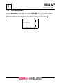
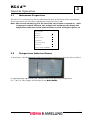
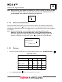
3.2
Temperature Indicator Screen
In this figure, the thermometer indicates operating temperature has not been reached.
In approximately 20 minutes the analyzer will reach operating temperature
(37° ± 0.5°C). The display will change to the MAIN MENU:
October 2001
3-1 EN
KC4 ∆™
3
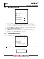
3.3
General Operation
Main Menu Functions
S I G M A - A M E L U N G
KC
4
DELTA
DATE: 12 Sep 2001
1
TIME:
10 : 08
2
PROGRAM SELECTION
3
PRINT PARAMETERS
4
Press ↵ to continue
1. To enter DATE, select 1. The date is in European format: dd,mm,yy.
12-09-2001 is September 12, 2001. The entry is confirmed with <↵> or
terminated with <ESC>. If terminated, the previous values remain valid.
2. To enter TIME, select 2. The format for time is hh:mm; example: 10:08
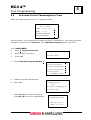
3. To modify Program Selection, select 3.
4. To PRINT a copy of all programmed tests and parameters, select 4.
5. To proceed to the Operating Screen, press <↵>.
3.4
Password Modification
From the Main Menu screen, press 3 Program Selection.
Password modify
1
Routine Program modify
2
Emergency Program modify
3
Individual Program modify
4
Delete all programs
5
Language modify
6
Press ↵ to continue
Parameter Check with Enter
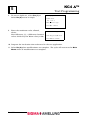
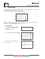
Select 1, Password modify. Enter a new password, Press <↵>. The default password
for a new analyzer is 1 2 3 4.
Enter Password:
Press ↵ to continue.
3-2 EN
October 2001
KC4 ∆™
General Operation
3.5
3
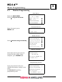
Program Modification
Selecting the tests to be available for each program
The programs ( Routine, Emergency, Individual) are modified by selecting tests from the
keypad to form a desired group.
From the Main Menu screen, select 3 Program Selection. From the Program
Selection screen, select:
2 Modify the Routine Program: This function allows the operator to select the tests
available to be run in the Routine Program. The tests are selected by pressing keys
(INR, APTT, FIB, etc.) and confirming with <↵>. Terminating is possible with
<ESC>. Upon termination, the previously set values will remain valid. In this
program, the analyzer will allow a sequential operation of tests (Batch – mode).
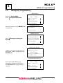
3 Modify the Emergency Program: This function allows the operator to select the
tests available to be run in the Emergency Program. The tests are selected by
pressing keys (INR, APTT, FIB, etc.) and confirming with <↵>. Terminating is possible
with <ESC>. Upon termination, the previously set values will remain valid. The
analyzer will do a selected profile of tests on a single patient (Patient – Selective).
4 Modify the Individual program: This function allows the operator to individualize
the test menu by sample if desired. The tests in the Individual Program are chosen
directly from the keyboard by pressing keys (INR, APTT, FIB, etc) and confirming
with <↵>. Terminating is possible with <ESC>. Upon termination, the previously set
values will remain valid.
5 To delete all programs.
6 Language Modify
Parameter Check with Enter
WARNING: All tests in the programs and all test parameters can be deleted with
one keystroke. A complete new installation of programs is necessary if all
programs are deleted.
See Section 4 for a more detailed description of Program Modification.
October 2001
3-3 EN
KC4 ∆™
3
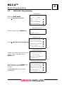
3.6
General Operation
Reagent Handling
Reagents for the appropriate test are prepared according to the manufacturer’s
instructions. Refer to the manufacturer’s reagent application for specific instructions
on preparation and handling of reagents. Any reagent requiring pre-heating should be
placed into a 15-mm tube and inserted into the reagent incubation well. The fluid level
in the tube should not be above the top edge of the incubation well. A minimum of
15 minutes will be required to warm reagent to 37°C ± 0.5°C. (Note: Reagents direct
from the refrigerator may take slightly longer to warm up.) All reagents should be
used before the expiration date listed by the manufacturer for each reagent. Do not
place any opened reagent bottles on the instrument.
3.7
Cuvette Preparation
Tetravettes or micro cuvettes are placed in racks in the unheated preparation area.
Up to twelve (12) cuvettes can be placed on the instrument. The exact size and surface
quality of the cuvettes is critical to the proper performance of testing. Absolute
cleanliness of cuvettes is mandatory to ensure correct performance. The cuvettes are
intended as one-time use items. Rewashing cuvettes is not recommended. The
performance of substitute cuvettes cannot be guaranteed; therefore, substitute
cuvettes should not be used.
Tetravettes are cuvettes in pre-packaged groups of 4. They contain a stainless steel ball
and can go directly into a loading rack and onto the instrument.
The stainless steel balls are manufactured from a special stainless steel. Purity, weight,
size, surface quality and magnetic characteristics of the balls are all critical to the
proper performance of testing. The balls, which are manufactured by Sigma/Amelung
have been tested to ensure compatibility with the instrument measurement process
and that they are inert when used with plasma and coagulation reagents. Rust, slight
impurities or oil residue can have an adverse effect on coagulation testing results.
The balls are intended as one-time use items. Recycling balls is not recommended.
The performance of substitute balls cannot be guaranteed; therefore, substitute balls
should not be used. The ball dispenser used in conjunction with the micro cuvettes,
has been designed to facilitate transfer of balls into the cuvettes.
3-4 EN
October 2001
KC4 ∆™
General Operation
3.8
3
Sample Preparation
Plasma samples and reagents are added with appropriate microliter pipettes. Refer to
the manufacturer’s reagent application to determine the sample and reagent(s) volume
required for each test. Pipetting technique is critical to the performance of testing. Refer
to the Pipetting section for guidelines in proper pipetting technique. Although the use of
a Multipette will facilitate initiation of measurement timing, special pipettes are not
required. If a Multipette is not available, measurement timing can be started using the
start button and channel buttons.
Sample is dispensed into the cuvette. Twelve o’clock is the recommended dispense
position. After sample has been dispensed, close the Plexiglas flap, pick the cuvette
rack up and swirl gently to evenly disperse the sample over the bottom of the cuvettes.
Place the rack with cuvettes in the rotating test positions ensuring that the cuvettes are
pressed firmly down to the bottom. Two additional racks of cuvettes (4 each) may also
have samples pipetted and placed in the reaction incubation wells.
Care must be taken not to over incubate the samples. It is advisable to stagger the time
interval between the cuvette racks in the heated incubation wells and rotating test
positions to prevent over incubation. Allow the samples to pre-incubate for the
recommended time. It will take slightly longer (a minimum of 120 seconds) for a sample
that has been stored at refrigerator temperature (2–8°C) to reach 37°C than for samples
stored at room temperature (18–26°C). Several of the coagulation factors, (Factors V,
VIII, XIII, and fibrinogen) are labile at 37°C. To avoid loss of these factors, samples
should not be pre-incubated longer than 5 minutes.
Timing is critical in coagulation testing and the reagent manufacturer’s guidelines for
incubation times should be followed. Any particulate reagent must be well mixed prior
to use. For those tests, having more than one reagent, all incubations prior to
measurement start can be accomplished in the reaction incubation wells. Nine o’clock
is the recommended first-reagent dispense position.
Care must be taken to avoid contact of the reagent pipette tip with previously dispensed
sample. After addition of reagent, close the Plexiglas lid, pick up the cuvette rack, and
swirl gently 5–6 times to mix the reagent and previously pipetted sample. The reaction
mixture should be evenly dispersed around the channel at the bottom of the cuvette. No
more cuvettes should be prepared for testing than can be completed within the
specified guidelines.
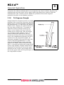
In most instances, addition of a start reagent begins the coagulation process. It is
important that the Measurement Timer
or Multipette be started simultaneously to
the addition of the start reagent in order to ensure accuracy and precision of the assay.
Test measurement timing can be started either manually using the Channel Key
or
automatically by using the Multipette fitted with a starter cable. Use of a Multipette will
ensure that the reagent addition starts measurement timing. Directions for both
manual start and automatic start are described below.
The location of the start reagent dispense is important. To ensure that mixing of start
reagent with the previously pipetted sample or sample/reagent mixture begins
immediately, the start reagent should be dispensed just to the right side of the ball.
This is best accomplished by holding the pipette angled obliquely from the right rear
side of the cuvette towards the ball position and dispensing the reagent just to the right
October 2001
3-5 EN
KC4 ∆™
3
General Operation
of the ball. Care must be taken to avoid splashing the reagent out of the cuvette. The
dispense rate should be of moderate speed and forcefulness.
3.9
Pipetting
The overall performance of the KC4 ∆™ Coagulation Analyzer is dependent on the
accuracy and precision of pipetting both sample and reagent(s).
Testing can be performed with either standard microliter pipette(s) or with the
Multipette fitted with a starting cable. When the Multipette is used to dispense the final
start reagent, the timer is automatically started simultaneously with reagent dispense.
When a standard microliter pipette is used for addition of the final start reagent, the
timer is started manually using the Specific Channel Key.
Regardless of what kind of pipette is used, the care taken with pipetting is directly
proportional to the overall accuracy and precision of testing.
To avoid contamination of reagents, if the same pipette is being used for both sample
and reagent, a new tip must be used when transitioning between sample and reagent.
To avoid cross-contamination between samples, a new tip should be used for each
sample, whether running plasma or whole blood samples.
Pipetting Technique for Non-Repeating Pipettes
To fill the pipette tip: Depress the button to the first stop. With the button depressed,
insert the tip into the sample or reagent to a depth of approximately 2–3 mm. If
pipetting plasma directly from a centrifuged tube of blood, the tip should be kept well
away from the blood/plasma interface. This will assure that no red cells or platelets will
be aspirated into the tip. If pipetting a particulate reagent, the reagent should be well
mixed prior to aspiration.
Release the button slowly in such a manner that the sample or reagent flows smoothly
into the pipette tip. Slow aspiration will assure that the volume aspirated into the tip is
accurate. If the button is allowed to snap back, an incorrect volume may be aspirated.
In addition, sample or reagent can be aspirated into the barrel of the pipette. This can
result in contamination of subsequent samples or reagents. Unless the pipette is
dismantled and cleaned, inadvertent aspiration into the pipette barrel will result in
eventual obstruction and incorrect operation of the pipette.
Once the tip is filled, no dripping should be observed. If dripping is observed, either the
tip is not seated correctly on the pipette or the pipette requires maintenance. In such a
circumstance, replace the tip. If this does not correct the problem, the pipette should
not be used until maintenance can be performed.
Pipetting Technique for Multipettes
Only pipette tips recommended for use with the pipette should be used. Any pipette tip
whose insertion opening is out-of-round should be discarded. Any pipette tips that are
bent or otherwise damaged should be discarded. The tip opening must not be occluded.
Slide the filling lever down until it stops, then raise the locking clamp upward.
Insert the combitip until it clicks into position. Be sure the combitip plunger is fully
inserted into the barrel before attaching it to the Multipette. Be sure the filling lever is
completely down and then lower the locking clamp to secure the combitip in place.
3-6 EN
October 2001
KC4 ∆™
General Operation
3
Verify that the volume selection dial is set to dispense the correct volume. Immerse the
combitip cone into the liquid. Fill by slowly sliding the filling lever upward. Wipe the
combitip cone with a lint-free tissue. Follow the guidelines for correct dispense
positions described in the following sections.
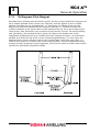
3.10
To Dispense Sample
Sample should be dispensed to the 12 o'clock
position of the cuvette (see diagram). Aim the
pipette to the 12 o'clock position. Position the
tip approximately 3–4 mm above the bottom
of the cuvette. Depress the pipette button to
the first stop and hold for 1–2 seconds to
allow the residual contents of the tip to
collect at the bottom of the tip. Press the
button to the second stop. This will deliver
any residual sample into the cuvette. To
avoid bubbling and splattering, the tip
should not be placed so close to the bottom
that at the completion of pipetting the tip is
submersed in the dispensed sample. An
alternative method is to touch the tip to the
cuvette sidewall approximately 3–4 mm
above the bottom of the cuvette and then
depress the button slowly to the first stop.
Wait 1–2 seconds and press the button to the
second stop position. Sample should not be
dispensed by touching the tip to the upper
sidewalls of the cuvette. Any sample that is
left on the upper walls will not participate in
the coagulation reaction.
October 2001
3-7 EN
KC4 ∆™
3
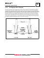
3.11
General Operation
To Dispense First Reagent
For those tests utilizing more than one reagent, the first reagent should be dispensed to
the 9 o'clock position of the cuvette (see diagram). Aim the pipette to the 9 o'clock
position. Position the tip approximately 3–4 mm above the bottom of the cuvette.
Depress the pipette button to the first stop and hold for 1–2 seconds to allow the
residual contents of the tip to collect at the bottom of the tip. Press the button to the
second stop. This will deliver any residual reagent into the cuvette. To avoid bubbling
and splattering, the tip should not be placed so close to the bottom that at the
completion of pipetting the tip is submersed in the dispensed reagent. An alternative
method is to touch the tip to the cuvette sidewall approximately 3–4 mm above the
bottom of the cuvette and then depress the button slowly to the first stop. Wait 1–2
seconds and press the button to the second stop position. To avoid contamination of
reagent during subsequent reagent pipetting, care must be taken to avoid contact of the
tip with the previously dispensed sample.
3-8 EN
October 2001
KC4 ∆™
General Operation
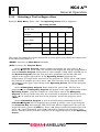
3.12
3
To Dispense Start Reagent
The Start Reagent is the reagent that, when added, begins the coagulation reaction.
Start Reagent should be dispensed just to the right side of the ball. This positioning
assures that mixing of reagent with the other reaction constituents begins immediately.
Holding the pipette obliquely from the right side, aim the pipette tip to the right side of
the ball. Position the tip approximately 5–6 mm above the ball. Depress the pipette
button to the last stop position. The dispense rate should not be so rapid or forceful
that reagent is splashed out of the cuvette. To avoid contamination of reagent during
subsequent reagent pipetting, care must be taken to avoid contact of the tip with the
previously dispensed sample and/or reagent (see diagram).
October 2001
3-9 EN
KC4 ∆™
3
3.13
General Operation
Selecting a Test to Begin a Run
From the Main Menu, Press < ↵ >. The Operating Screen will be displayed.
Operating Screen
37°C
Pat. ID: 333
Position
1
2
3
4
Inc. Time
0
0
0
0
Meas. Time
0
0
0
0
1
2
3
4
Start Inc.
Ready
The upper left shows the current patient ID and the upper right shows the temperature
of the measuring block in °C.
<MENU> Accesses up Main Menu functions.
<RUN> accesses the Program Menu.
Select 1 Routine Program. Select number of samples per rack, press < ↵ >.
Enter the Patient ID, press < ↵>. The analyzer will display the first test programmed
into the Routine Program (see Section 4). For example, if INR, APTT and FIB are in
the Routine Program, then the first test to be performed will be INR. INR will
appear in the upper right corner of the Operating Screen (replacing the
temperature). To scroll to the next test in the program (ie. APTT), press < ↵>. Enter
the number of samples per rack, press < ↵>. The next test in the program (APTT),
will appear in the upper right corner of the Operating Screen. To end the program,
press <RUN>.
Select 2 Emergency Program. Enter Patient ID, press < ↵>. The first test
programmed in the Emergency Program will appear in the upper right corner of the
Operating Screen. Only one sample at a time can be run in the Emergency
Program. At the end of the first test, the result will be displayed. Record the result,
Press < ↵> to scroll to the next test in the program. To end the program, press
<RUN>.
Select 3 Individual Program. A grid of available tests programmed into the
Individual Program will be displayed (see section 4). Select a test by pressing the
test Function Key. For example, INR, APTT and FIB are displayed on the grid. To
begin INR testing, press the INR key. Press < ↵>. Enter number of samples per rack,
press < ↵>; enter Patient ID, press < ↵>. INR will be displayed in the upper right
corner, and the Patient ID will be displayed in the upper left corner of the Operating
Screen.
3-10 EN
October 2001
KC4 ∆™
3
General Operation
Note: When entering the number of samples per rack: if testing in duplicate, Max
would be 2 and the choice of 1 pair or 2 pair per rack would be made. It is
recommended that samples be analyzed in duplicate.
Samples per rack
Count: 2
Max = 2
3.14
Patient Identification
After the number of samples per rack has been entered, the analyzer will ask for a
Patient ID number. Press 1 to enter a Patient ID. The instrument will automatically
increment up from this number. Press 2 to enter a specific Patient ID for the samples to
be analyzed.
Note: This screen must be re-accessed to enter subsequent Patient ID
numbers. To do this, press the RUN key, select 3 Individual Program.
Press the appropriate test key. Theer the number of samples per rack
(2 when analyzing in duplicate); select 2 for manual Patient ID entry.
ROUTINE PROGRAM
Patient ID:
Start Patient ID Modify
Manual Patient ID
1
2
Press ↵ to Continue
3.15
Testing
1. With the transfer of the first rack to the rotating wells, Press Incubation timer:
Operating Screen
Patient ID: 333
INR
Position
1
2
3
4
Inc. Time
0
0
0
0
Meas. Time
0.0
0.0
0.0
0.0
Start Inc.
***
***
READY
2. Press Channel timer
October 2001
for each sample to be tested.
3-11 EN
KC4 ∆™
3
General Operation
3. Each channel will begin the incubation countdown. An audible beep will occur
when 5 seconds remain.
4. Press and hold down the <START> key and begin dispensing the start reagent.
3.16
Manual Start Procedure
Install a pipette tip onto an appropriately sized pipette.
Mix particulate reagent by covering the tube with Parafilm® and inverting gently. Do
not shake. Many coagulation reagents are mixtures of lipids, which will undergo spatial
rearrangement when shaken.
Aspirate reagent into the pipette tip. Dispense one aliquot of reagent into reagent
container to prime the pipette tip.
Press the <START> key.
Dispense reagent just to the right side of the ball and simultaneously press the Specific
Channel Key
.
Note: Measurement can be started automatically if the reagent is dispensed with
enough force to move the ball from its steady position. This is best
accomplished by dispensing the reagent directly onto the right side of the
ball. This dispense should not be so forceful that any of the reaction
mixture is splashed out of the cuvette. This is not as reliable a way to start
timing. It is particularly unreliable when dispensing a volume less than
100 µl.
3.17
Automatic Start Procedure
The KC4∆ Multipette is recommended for use in the Automatic Start Procedure.
Assure that the Multipette cable is plugged into the Automatic Pipette socket located on
the rear of the KC4∆ Coagulation Analyzer.
Install appropriately sized pipette tip.
Mix particulate reagent by covering the tube with Parafilm® and inverting it gently. Do
not shake. Many coagulation reagents are mixtures of lipids, which will undergo spatial
rearrangement when shaken. The reactivity of such reagents is dependent on the
specific lipid arrangement.
Aspirate start reagent into the pipette tip. Dispense one aliquot of reagent into reagent
container to prime the pipette tip.
Press the <START> key.
Fully depress the pipetting lever to dispense reagent. This is best accomplished by
holding the pipette angled obliquely from the right rear side and dispensing the reagent
just to the right side of the ball. Measurement timing is started automatically.
Return the pipette to the heated pipette tube holder. Note: Replace the pipette tube
holder sleeves daily and for each new reagent. Pipette tube holder sleeves should be
treated as biohazardous waste.
3-12 EN
October 2001
KC4 ∆™
General Operation
3
Note: To increase speed when using an automatic multipette with starting cable,
simple keep the Start Key of the first channel depressed while pipetting.
Thus, when channel 1 is pipetted and the timer for channel 1 is started, the
timer for channel 2 is activated. When channel 2 is pipetted, its timer
begins and channel 3’s timer is activated, etc.
With the addition of start-reagent, initiation of the coagulation process begins. As
coagulation takes place, fibrinogen polymerizes to form strands of fibrin. The formed
fibrin sweeps the ball out of its steady position, which triggers an impulse in the
magnetic sensor. This impulse electronically stops the timer signifying the end of
measurement time. The elapsed time will be displayed in seconds and tenths of
seconds.
3.18
Printing Results
1. The printer will immediately print out the results of the first test. The second test
results will be printed after <↵> is pressed.
Individual Program: INR
Date
: 25 Nov 2001
Time
: 01:11
Patient ID : 25
Measured Values:
Value 1
: 12,4 sec
Value 2
: 12,1 sec
Average Value
: 12,25 sec
Difference
: 2,4 %
Result : 1,02
Individual Program: INR
Date:
25 Nov 2001
Time:
01:12
Patient ID: 26
Measured Values:
Value 1
: 12,0 sec
Value 2
: 12,3 sec
Average Value
: 12,15 sec
Difference
: 2,4 %
Result : 1,01
Individual Program: INR
Date:
25 Nov 2001
Time:
01:14
Patient ID: 27
Measured Values:
Value 1
: 11,5 sec
Value 2
: 11,2 sec
Average Value
: 11,35 sec
Difference
: 2,6 %
Result : 0,93
October 2001
3-13 EN
KC4 ∆™
Mode Programming
4
4Mode Programming
Contents
4.1
ROUTINE PROGRAMMING...................................................................... 4-1
4.2
EMERGENCY PROGRAMMING ................................................................ 4-2
4.3
INDIVIDUAL PROGRAMMING ................................................................. 4-3
October 2001
4-0 EN
KC4 ∆™
4
Mode Programming
4.1
Routine Programming
Main Menu
S I G M A - A M E L U N G
From the MAIN MENU:
Select 3, Program Selection.
KC
4
DELTA
DATE: 12 Sep 2001
1
TIME:
10 : 08
2
PROGRAM SELECTION
3
PRINT PARAMETERS
4
Password Screen
Enter Password, press
Enter Password:
ENTER <↵>.
Press ↵ to continue.
Modify Screen
Press 2, Routine Program Modify.
Password Modify
1
Routine Program Modify
2
Emergency Program Modify
3
Individual Program Modify
4
Delete all programs
5
Language Modify
6
Parameter Check to Enter
Routine Program
Tests
Select from the keypad all tests
desired for this group. When
complete, press ENTER <↵>.
In Routine Program
INR APTT FIB
New entry press ENTER to store
Press ESC to cancel
Programming Screen
Tests programmed will cycle,
allowing parameter changes to be
made.
See Section 5 regarding
programming tests.
October 2001
Password Modify
1
Routine Program Modify
2
Emergency Program Modify
3
Individual Program Modify
4
Delete all programs
5
Press ENTER to continue
4-1 EN
KC4 ∆™
4
4.2
Mode Programming
Emergency Programming
Main menu
S I G M A - A M E L U N G
From the MAIN MENU:
Press 3, Program Selection.
KC
4
DELTA
DATE: 12 Sep 2001
1
TIME:
10 : 08
2
PROGRAM SELECTION
3
PRINT PARAMETERS
4
Password Screen
Enter Password, press ENTER <↵>
to continue.
Enter Password:
Press ↵ to continue.
Modify Screen
Press 3, Emergency Program
Modify.
Password Modify
1
Routine Program Modify
2
Emergency Program Modify
3
Individual Program Modify
4
Delete all programs
5
Press ENTER to continue
Emergency Screen
Tests
Choose tests from the keypad for
this group. When complete, press
ENTER <↵>.
In Emergency program
INR APTT FIB
New entry press ENTER to store
Press ESC to cancel
Programming Screen
S I G M A - A M E L U N G
Tests will cycle allowing for
Parameter changes to be made.
See Section 5 for programming
changes.
4-2 EN
KC
DATE:
TIME:
4
DELTA
12 Sep 2001
10 : 08
1
2
PROGRAM SELECTION
3
PRINT PARAMETERS
4
October 2001
KC4 ∆™
4
Mode Programming
4.3
Individual Programming
Main Menu
S I G M A - A M E L U N G
From the MAIN MENU:
Press 3, Program Selection.
KC
DATE:
TIME:
4
DELTA
12 Sep 2001
10 : 08
1
2
PROGRAM SELECTION
3
PRINT PARAMETERS
4
Password Screen
Enter Password:
Enter Password, press ENTER<↵>.
Press ↵ to continue.
Modify Screen
Press 4, Individual Program Modify
Password Modify
1
Routine Program Modify
2
Emergency Program Modify
3
Individual Program Modify
4
Delete all programs
5
Press ENTER to continue
Individual Screen
Tests
Choose tests from the keypad for this
group. When complete, press
ENTER <↵>.
In Individual Programming
INR APTT FIB
New entry press ENTER to store
Press ESC to cancel
Programming Screen
When complete, press ENTER <↵>.
Tests will cycle for parameter
changes.
See Section 5 for programming
information.
October 2001
Password Modify
1
Routine Program Modify
2
Emergency Program Modify
3
Individual Program Modify
4
Delete all programs
5
Press ENTER to continue
4-3 EN
KC4 ∆™
Test Programming
5
5Test Programming
Contents
5.1
INR........................................................................................................ 5-1
5.2
INR FLOW CHART.................................................................................. 5-3
5.3
PROTHROMBIN TIME (PERCENT ACTIVITY CURVE)............................... 5-4
5.4
PT (PERCENT ACTIVITY) FLOW CHART.................................................. 5-7
5.5
RATIO FLOW CHART ............................................................................. 5-8
5.6
ACTIVATED PARTIAL THROMBOPLASTIN TIME..................................... 5-9
5.7
APTT FLOW CHART ..............................................................................5-11
5.8
FIBRINOGEN ........................................................................................5-12
5.9
FIBRINOGEN FLOW CHART ..................................................................5-15
5.10
FACTORS..............................................................................................5-16
5.11
FACTORS FLOW CHART .......................................................................5-19
5.12
STATS ..................................................................................................5-20
October 2001
5-0 EN
KC4 ∆™
5
Test Programming
5.1
INR
The INR (International Normalized Ratio) is the preferred method for reporting
Prothrombin Times in the United States. The PT percent activity curve and ratio are
preferred in Europe.
Allow the instrument to reach 37°C prior to testing.
S I G M A - A M E L U N G
KC
DATE:
TIME:
4
DELTA
12 Sep 2001
1
10 : 08
2
PROGRAM SELECTION
3
PRINT PARAMETERS
4
Prior to testing, a Test Program or profile needs to be established. The three programs
available are discussed in Section 4. The Individual Program will be used here.
At the MAIN MENU,
1. Press 3, Program Selection.
Enter Password:
2. Enter 4 digit Password:_ _ _ _;
3. Press <↵>.
Press ↵ to continue.
4. Select Individual Program Modify 4:
Password Modify
1
Routine Program Modify
2
Emergency Program Modify
3
Individual Program Modify
4
Delete all programs
5
Press ENTER to continue
5. Choose tests from the keypad.
Tests
6. Press <↵> to store.
In individual program
INR
New entry press ENTER ↵ to store
Press ESC to cancel
October 2001
5-1 EN
KC4 ∆™
5
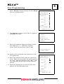
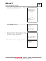
7. Select Yes (1) to change settings or
select No (2) to leave as programmed.
Test Programming
Program INR:
Incubation Time (sec) :
Default Value
:
ISI-Value
:
Max. Difference (%)
:
Modify? Yes 1
8. To test in duplicate, select Yes (1)
or No (2) for single testing, press <↵>.
No 2
INR – Program
Double Test?
Yes 1 No 2
Max. Difference (%) :
Press ↵ to continue
9. Enter the maximum difference allowed,
where:
Max difference (%) = (difference
between values divided
by the mean value) x 100
Max. Difference (%): 10
New entry press ↵ to store
Press ESC to continue
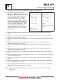
10. Program the incubation time referenced
in the test application.
11. Default Value is the PT Mean Normal*
Program INR:
12. ISI Value for the thromboplastin in
use.
Incubation Time (sec) : 60
Default Value
: 12,2
13. Max. Difference as determined above.
ISI-Value
: 1.78
14. Select No (2) when modification is
complete. The cycle will return to the
MAIN MENU when all modifications
are complete.
Max. Difference (%)
: 10
Modify? Yes 1
No 2
The KC4 ∆™ will automatically calculate the INR using the programmed values entered
for the mean of the Reference Range and the ISI value for the thromboplastin in use.
* Prior to entering values, a reference range should be determined for the lot number of
thromboplastin that will be used. Because PT reference ranges can vary between
laboratories and between different reagent formulations, determination of the reference
range on the population being served is recommended. For accurate INR reporting, the
determination of the geometric mean is recommended. When the geometric mean has
been determined, values may be programmed into the KC4 ∆™.
5-2 EN
October 2001
KC4 ∆™
5
Test Programming
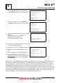
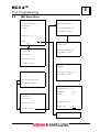
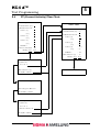
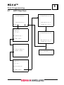
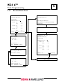
5.2
INR Flow Chart
Program INR
Program INR:
Incubation time (sec): ?
Incubation Time (sec) :
Default Value
:
ISI-Value
:
New entry press ↵ to store
Press ESC to continue
Max. Difference (%)
:
Modify?
No 2
Yes 1
Program INR
Default value:
INR – Program
New entry press ↵ to store
Double Test?
Press ESC to continue
Yes 1 No 2
Max. Difference (%) :
Press ↵ to continue
Program INR
ISI-Value:
Max. Difference (%): 10
New entry press ↵ to store
Press ESC to continue
New entry press ↵ to store
Press ESC to continue
Program INR:
Incubation Time (sec) : 60
INR – Program
Default Value
: 12,2
ISI-Value
: 1.78
Max. Difference (%)
: 10
Double Test?
Yes 1 No 2
Max. Difference (%) :
Press ↵ to continue
Modify? Yes 1
No 2
NEXT TEST
October 2001
5-3 EN
KC4 ∆™
5
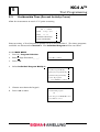
5.3
Test Programming
Prothrombin Time (Percent Activity Curve)
Allow the instrument to reach 37°C prior to testing.
S I G M A - A M E L U N G
KC
DATE:
TIME:
4
DELTA
12 Sep 2001
1
10 : 08
2
PROGRAM SELECTION
3
PRINT PARAMETERS
4
Prior to testing, a Test Program or profile needs to be established. The three programs
available are discussed in Section 4. The Individual Program will be used here.
At the MAIN MENU:
Enter Password:
1. Press 3, Program Selection.
2. Enter 4 digit Password:_ _ _ _;
Press ↵ to continue.
3. Press <↵>.
4. Select Individual Program Modify 4.
Password Modify
1
Routine Program Modify
2
Emergency Program Modify
3
Individual Program Modify
4
Delete all programs
5
Press ENTER to continue
5. Choose tests from the keypad.
Tests
6. Press <↵> to store.
In individual program
PT
New entry press ENTER ↵ to store
Press ESC to cancel
5-4 EN
October 2001
KC4 ∆™
5
Test Programming
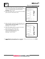
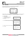
7. Select Yes (1) to change settings or select No (2)
to leave as programmed.
Program PT:
Incubation Time (sec) : ?
Calibration Curve PT : ?
Point 1 (%)
(sec)
Point 2 (%)
(sec)
Point 3 (%)
(sec)
PT MAX %
: ?
: ?
: ?
: ?
: ?
: ?
: ?
Difference Check PT : No
Modify? Yes 1 No 2
8. Press Yes (1) if testing is to be done in duplicate,
or No (2) if in single.
PT – Program
Double Test?
Yes 1 No 2
Max. Difference (%) :
Press ↵ to continue (more
parameters)
9. Enter the maximum difference allowed, where:
Max difference (%) = (difference between
values divided by the mean value) x 100
Max. Difference (%): ?
New entry press ↵ to store
Press ESC to continue
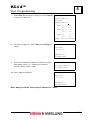
10. Program the incubation time referenced in the
test application.
11. Enter the reference value of the PT calibration
curve. This is the first point, the highest point of
the curve. This does not have to be 100%, it may
vary depending on the source of the reference
plasma.
12. Enter the clotting time in seconds of the first
point of the PT calibration curve.
Program PT:
Incubation Time (sec) : 60
Calibration Curve PT : ?
Point 1 (%)
(sec)
Point 2 (%)
(sec)
Point 3 (%)
(sec)
PT MAX %
Max. Difference (%)
: 100
: 12
:
:
:
:
:
: 10
Modify? Yes 1 No 2
October 2001
5-5 EN
5
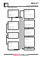
13. Enter the second value of the PT calibration
curve. The second point, the middle point of the
curve is a dilution of the reference plasma.
Example: 30% is used.
14. Enter the clotting time in seconds for the middle
point of the PT calibration curve.
KC4 ∆™
Test Programming
Program PT:
Incubation Time (sec) : 60
Calibration Curve PT : ?
Point 1 (%)
(sec)
Point 2 (%)
(sec)
Point 3 (%)
(sec)
PT MAX %
Max. Difference (%)
: 100
: 12
: 30
: 27
:
:
:
: 10
Modify? Yes 1 No 2
15. Enter the third value of the PT calibration curve.
The third point, the lowest point of the curve is a
dilution of the reference plasma.
Example: 12.5% is used:
16. Enter the clotting time in seconds of the third
point of the PT calibration curve.
17. Enter the Maximum % PT value.
Values exceeding maximum value
entered are not printed out.
Example: 130% is used.
Program PT:
Incubation Time (sec) : 60
Calibration Curve PT : ?
Point 1 (%)
(sec)
Point 2 (%)
(sec)
Point 3 (%)
(sec)
PT MAX %
Max. Difference (%)
: 100
: 12
: 30
: 27
: 12.5
: 62
: 130
: 10
Modify? Yes 1 No 2
18. Select No (2), when modification is complete. The cycle will return to the MAIN
MENU when all modifications are complete.
5-6 EN
October 2001
KC4 ∆™
5
Test Programming
5.4
PT (Percent Activity) Flow Chart
Program PT:
Incubation Time (sec) : ?
NEXT TEST
Calibration Curve PT : ?
Point 1 (%)
(sec)
Point 2 (%)
(sec)
Point 3 (%)
(sec)
PT MAX %
: ?
: ?
: ?
: ?
: ?
: ?
: ?
Difference Check PT : No
Modify? Yes 1 No 2
Program PT:
Incubation Time (sec) : 60
Calibration Curve PT : ?
Point 1 (%)
(sec)
Point 2 (%)
(sec)
Point 3 (%)
(sec)
PT MAX %
Max. Difference (%)
: 100
: 12
: 30
: 27
: 12.5
: 62
: 130
: 10
Modify? Yes 1 No 2
PT – Program
Double Test?
Yes 1 No 2
Max. Difference (%)
NEXT TEST
Press ↵ to continue
Max. Difference (%) ?
New entry press ↵ to store
Press ESC to continue
PT – Program
Double Test?
Yes 1 No 2
Difference Check: No
Press ↵ to continue
October 2001
5-7 EN
KC4 ∆™
5
5.5
Test Programming
Ratio Flow Chart
PROGRAM RATIO:
PROGRAM RATIO:
Incubation time (sec): 0
Incubation time (sec): 0
Default Value: 0,0
Default Value: 0,0
Max. Difference (%): ?
Difference Check RATIO: No
RATIO: No
Modify? Yes 1
No 2
Modify? Yes 1
No 2
Program RATIO
RATIO – Program
Incubation time (sec): 0
Double Test?
Yes 1 No 2
New entry press ↵ to store
Press ESC to continue
Max. Difference (%): ?
Press ↵ to continue
Press ESC to continue
Program RATIO
Default Value:
Max. Difference (%):
New entry press ↵ to store
Press ESC to continue
New entry press ↵ to store
Press ESC to continue
PROGRAM RATIO:
Incubation time (sec): 0
Default Value: 0,0
RATIO – Program
Double Test?
Max. Difference (%): 5%
Yes 1 No 2
RATIO: No
Modify? Yes 1
No 2
Max. Difference (%):
NEXT TEST
Press ↵ to continue
5-8 EN
October 2001
KC4 ∆™
5
Test Programming
5.6
Activated Partial Thromboplastin Time
Allow the instrument to reach 37°C prior to testing.
S I G M A - A M E L U N G
KC
DATE:
TIME:
4
DELTA
12 Sep 2001
10 : 08
1
2
PROGRAM SELECTION
3
PRINT PARAMETERS
4
Prior to testing, a Test Program or profile needs to be established. The three programs
available are discussed in Section 4. The Individual Program will be used here.
At the MAIN MENU:
1.
Press 3, Program Selection.
2.
Enter 4 digit Password:_ _ _ _;
3.
Press <↵>.
4. Press Individual Program Modify 4.
Enter Password:
Press ↵ to continue.
Password Modify
1
Routine Program Modify
2
Emergency Program Modify
3
Individual Program Modify
4
Delete all programs
5
Press ENTER to continue
5. Choose tests from the keypad.
Tests
6. Press <↵>.
In individual program
APTT
New entry press ENTER ↵ to store
Press ESC to cancel
7. Select Yes (1) to change settings or
select No (2) to leave as programmed.
Program – PTT
Incubation time (sec): 240
Max. Difference (%): ?
Modify? Yes 1 No 2
October 2001
5-9 EN
KC4 ∆™
5
8. To test in duplicate, select Yes (1) or
Select No (2) to test in single.
Test Programming
PTT – program
Double Test?
Yes 1 No 2
Max. Difference (%): ?
Press ↵ to continue
9. Enter the maximum value allowed,
where:
Max difference (%) = (difference between
values divided by the Mean value) x 100.
Max. Difference (%): 10
New entry press ↵ to store
Press ESC to continue
10. Program the incubation time referenced in the test application.
11. Select No (2) when modifications are complete. The cycle will return to the Main
Menu when all modifications are complete.
5-10 EN
October 2001
KC4 ∆™
5
Test Programming
5.7
APTT Flow Chart
Program – PTT
Program – PTT
Incubation time(sec): ?
Incubation time (sec): 240
Max. Difference(%): ?
Max. Difference (%): 10
Modify? Yes 1
No 2
Modify? Yes 1 No 2
PTT – program
Double Test?
Yes 1 No 2
Program – PTT
Incubation time (sec): 240
Max. Difference(%): ?
Press ↵ to continue
Max. Difference (sec): 10
Modify? Yes 1 No 2
Max. Difference(%): ?
New entry press ↵ to store
Press ESC to continue
Next Test
PTT – program
Double Test?
Yes 1 No 2
Difference Check: No
Press ↵ to continue
October 2001
5-11 EN
KC4 ∆™
5
5.8
Test Programming
FIBRINOGEN
Prior to programming Fibrinogen, the concentration of the calibration curve points and
the clotting time for each point must be known.
Allow the instrument to reach 37°C prior to testing.
S I G M A - A M E L U N G
KC
DATE:
TIME:
4
DELTA
12 Sep 2001
1
10 : 08
2
PROGRAM SELECTION
3
PRINT PARAMETERS
4
Prior to testing, the test must be programmed into a testing format as discussed in
Section 4. The Individual Program will be used here.
At the MAIN MENU:
1. Press 3, for Program Selection.
Enter Password:
2. Enter 4 digit Password:_ _ _ _.
3. Press <↵>.
Press ↵ to continue.
4. Press Individual Program Modify 4.
Password Modify
1
Routine Program Modify
2
Emergency Program Modify
3
Individual Program Modify
4
Delete all programs
5
Press ENTER to continue
5. Choose tests from the keypad.
Tests
6. Press <↵>.
In individual program
FIB
New entry press ENTER ↵ to store
Press ESC to cancel
5-12 EN
October 2001
KC4 ∆™
5
Test Programming
7. To modify, select Yes (1) to change or, No (2) to
test in leave as programmed.
Program – FIB:
Incubation Time (sec) :
Calibration Curve FIB:
Point 1 (G/L)
:
(sec)
:
Point 2 (G/L)
:
(sec)
:
Point 3 (G/L)
:
(sec)
Dilution
:
1:5
Max. Difference (%)
:
Modify? Yes 1 No 2
8. Press Yes (1) if testing is to be done in duplicate
or Press No (2) if in single.
FIB – Program
Double Test?
Yes 1 No 2
Max. Difference (%) :
Press ↵ to continue
9. Enter the maximum difference allowed, where:
Max difference (%) = (difference between values
divided by the Mean value) x 100
Max. Difference (%):
New entry press ↵ to store
Press ESC to continue
10. Press <↵> to continue changing parameters.
FIB – Program
Double Test?
Yes 1 No 2
Max. Difference (%) :
Press ↵ to continue
October 2001
5-13 EN
KC4 ∆™
5
Test Programming
11. Choose the incubation time referenced in the test application.
12. Enter the reference value of the
Fibrinogen reference plasma in G/L
for the first point of the curve. This
can vary depending on the source
of the reference plasma. When
using the KC4 ∆™ Coagulation
Analyzer, care should be taken that
the clot time of the highest point is
more than the minimum read time
(4.5 sec.) of the instrument. This
can be achieved by utilizing the
optimal dilutions for the reference
plasma referred to in the reagent
applications.
Program – FIB:
Program – FIB:
Incubation Time (sec) :
Incubation Time (sec) :
Calibration Curve FIB:
Calibration Curve FIB:
Point 1 (G/L)
:
(sec)
:
Point 2 (G/L)
:
(sec)
(sec)
:
Point 5 (G/L)
:
(sec)
:
:
Dilution
:
Difference Check FIB : No
1:5
Max. Difference (%)
:
(sec)
:
Point 3 (G/L)
Dilution
Point 4 (G/L)
1:5
Modify? Yes 1 No 2
:
Modify? Yes 1 No 2
13. Enter the clotting time in seconds for the first point of the Fibrinogen reference
curve.
14. Enter the second value for the Fibrinogen reference curve. The second point is a
dilution of the reference plasma.
15. Enter the clotting time in seconds for the second point of the Fibrinogen reference
curve.
16. Enter the third value for the Fibrinogen reference curve. The third point is a
dilution of the reference plasma.
17. Enter the clotting time in seconds for the third point of the Fibrinogen reference
curve.
18. Enter the fourth value of the Fibrinogen reference curve. The fourth point is a
dilution of the reference plasma.
19. Enter the clotting time in seconds for the fourth point of the Fibrinogen reference
curve.
20. Enter the fifth value of the Fibrinogen reference curve. The fifth point is a dilution
of the reference plasma.
21. Enter the clotting time in seconds for the fifth point of the Fibrinogen reference
curve.
22. Enter the dilution for the patient or control samples to be analyzed. Fibrinogens
use a 5 point reference curve.
23. Select No (2) when modifications are complete. The cycle will return to the Main
Menu when all modifications are complete.
Note: Suggested dilutions and volumes used are found in the KC4 ∆™ Fibrinogen
Application.
5-14 EN
October 2001
KC4 ∆™
5
Test Programming
5.9
Fibrinogen Flow Chart
Program FIB
Incubation time (sec):
Program – FIB:
Incubation Time (sec) :
New entry press ↵ to store
Calibration Curve FIB:
Point 1 (G/L)
(sec)
Point 2 (G/L)
(sec)
Point 3 (G/L)
(sec)
Dilution
Max. Difference (%)
Press ESC to cancel
:
:
:
Program FIB
:
Calibration curve FIB :
:
New entry press ↵ to store
:
Press ESC to cancel
1:5
:
Modify? Yes 1
Program FIB
No 2
Point 1 (G/L) :
New entry press ↵ to store
FIB – program
Press ESC to cancel
Double Test?
Yes 1 No 2
Continue through all parameters
Max. Difference(%):
of the program.
Press ↵ to continue
Program – FIB:
Max. Difference (%):
Incubation Time (sec) :
Incubation Time (sec) :
Calibration Curve FIB:
Calibration Curve FIB:
Point 1 (G/L)
New entry press ↵ to store
Press ESC to continue
:
(sec)
Point 2 (G/L)
:
(sec)
Yes 1 No 2
Max. Difference(%):
Press ↵ to continue
Dilution
:
(sec)
:
Point 5 (G/L)
:
Point 3 (G/L)
Double Test?
Point 4 (G/L)
:
(sec)
FIB – program
Program – FIB:
:
(sec)
:
:
Dilution
:
Difference Check FIB : No
1:5
1:5
Modify? Yes 1 No 2
Difference Check FIB : No
Modify? Yes 1 No 2
NEXT TEST
October 2001
5-15 EN
KC4 ∆™
5
5.10
Test Programming
FACTORS
Prior to programming Factors, the concentration of the calibration curve points must be
known and the clotting time for each point must be established.
Allow the instrument to reach 37°C prior to testing.
S I G M A - A M E L U N G
KC
DATE:
TIME:
4
DELTA
12 Sep 2001
1
10 : 08
2
PROGRAM SELECTION
3
PRINT PARAMETERS
4
Prior to testing, a Test Program or profile needs to be established. The three programs
available are discussed in Section 4. The Individual Program will be used here.
At the MAIN MENU:
1. Press 3, Program Selection.
Enter Password:
2. Enter 4 digit Password:_ _ _ _.
3. Press <↵>.
Press ↵ to continue.
4. Select Individual Program Modify 4.
Password Modify
1
Routine Program Modify
2
Emergency Program Modify
3
Individual Program Modify
4
Delete all programs
5
Press ENTER to continue
5. Choose desired tests from the keypad.
Tests
6. Press <↵>.
In individual program
FAC
New entry press ENTER ↵ to store
Press ESC to cancel
5-16 EN
October 2001
KC4 ∆™
5
Test Programming
7. Select Yes (1) to change settings or select No (2)
to go to the next test.
PROGRAM FAC Factor = 0
Incubation Time (sec) :
Count Points
:
Calibration Curve F ?
Point 1 (%)
(sec)
Point 2 (%)
(sec)
Point 3 (%)
(sec)
: 0,0
: 0,0
: 0,0
: 0,0
: 0,0
: 0,0
Modify? Yes 1 No 2 (next test)
8. To test in duplicate, select Yes (1) or No (2) for
single.
FAC – Program
Double Test?
Yes 1 No 2
Max. Difference: ?
Press ↵ to continue
9. Enter the maximum difference allowed, where:
Maximum value (%) = (difference between
values)/mean value x 100.
Max. Difference(%): 0
New entry press ↵ to store
Press ESC to continue
10. Press <↵> to continue.
FAC - Program
Double Test?
Yes 1 No 2
Max. Difference: ?
Press ↵ to continue
Note: Only one factor curve may be entered at a time.
October 2001
5-17 EN
5
KC4 ∆™
Test Programming
11. Enter the Factor that will be used.
PROGRAM FAC Factor = 0
12. Enter an incubation time referenced in the test
application.
Incubation Time (sec) :
13. Choose as many Curve Points (Count Points) as
appropriate for testing requirements (9 points max).
Calibration Curve F ?
14. Enter the reference value of the Factor calibration
curve. This is the first point, the highest point of the
curve. This does not always have to be 100%, it can
vary depending on the source of the reference plasma.
15. Enter the clotting time in seconds of the first point of
the Factor calibration curve.
16. Continue entering percentage points and seconds to
complete the calibration curve.
Count Points
:
Point 1 (%)
: 0,0
(sec)
Point 2 (%)
: 0,0
: 0,0
(sec)
Point 3 (%)
: 0,0
: 0,0
(sec)
: 0,0
Modify? Yes 1 No 2 (next test)
17. Select No (2) when modifications are complete. The cycle will return to the Main
Menu when all modifications are complete.
5-18 EN
October 2001
KC4 ∆™
5
Test Programming
5.11
Factors Flow Chart
PROGRAM FAC Factor = 0
Incubation Time (sec) :
Count Points
(sec)
Point 2 (%)
(sec)
Incubation time (sec):
:
Calibration Curve F ?
Point 1 (%)
Program FAC
: 0,0
: 0,0
New entry press ↵ to store
Press ESC to cancel (through remaining
parameters)
: 0,0
: 0,0
After final parameter has been entered.
Point 3 (%)
(sec)
: 0,0
: 0,0
Modify? Yes 1 No 2 (next test)
PROGRAM FAC Factor = 0
FAC – Program
Incubation Time (sec) :
Double Test?
Count Points
Yes 1 No 2
:
Calibration Curve F ?
Point 1 (%)
Max. Difference: ?
Press ENTER ↵ to continue
(sec)
Point 2 (%)
(sec)
Point 3 (%)
Max. Difference (%):
(sec)
: 0,0
: 0,0
: 0,0
: 0,0
: 0,0
: 0,0
New entry press ↵ to store
Press ESC to continue
FAC – Program
Modify? Yes 1
No 2 (next test)
NEXT TEST
Double Test?
Yes 1 No 2
Difference Check: No
Press ENTER ↵ to continue
October 2001
5-19 EN
KC4 ∆™
5
5.12
Test Programming
STATS
STATS are programmed in Section 4.2 Emergency Program.
1. From the MAIN MENU or if ROUTINE testing is in progress, press <↵> to bring up
the Operating screen:
2. From the keypad press <RUN>.
3. At the Test Selection Screen, choose Emergency Program (2) to bring up the
Operating Screen. If 2 beeps sound, nothing has been programmed; see
Section 4.
4. If multiple tests are grouped in the STAT Mode; press <↵> to change to other tests
in the group.
5-20 EN
October 2001
KC4 ∆™
6
Quality Control
6Quality Control
Regularly performed quality control is the best monitor of test performance. To assure
that control and unknown sample results are evaluated under the same test conditions,
control material should be included with each run.
The reagent manufacturer's QC recommendations should be used as a guide for
establishing a QC protocol. Control results deviating from established ranges are
indicative of a system failure and should be investigated immediately. The more
common sources of error and the corrective action to take are presented in the
Troubleshooting section, Section 8.
October 2001
6--1 EN
KC4 ∆™
Maintenance
7
7Maintenance
Introduction
There is no routine mechanical maintenance associated with the KC4 ∆™. The KC4 ∆™
was factory calibrated for rotational speed, magnetic sensor strength and temperature.
General housekeeping is the only maintenance that need be performed with any
regularity. Occasional cleaning with a damp paper towel is recommended to remove
accumulated dust or other material. Spills should be cleaned up as they occur.
Reagents can be corrosive and any spillage into the reagent incubation well should be
cleaned up immediately. All sample spills should be considered to have created a
potentially biohazardous environment and should be cleaned up immediately using
appropriate safeguards to avoid personal contamination. If decontamination is
required, wipe area with a paper towel moistened with a mild disinfectant.
Any balls that inadvertently find their way into the bottom of any of the wells can be
removed using a magnet.
October 2001
7-0 EN
KC4 ∆™
Troubleshooting
8
8Troubleshooting
Contents
8.1
TROUBLESHOOTING FLOW DIAGRAM ................................................... 8-1
8.2
TROUBLESHOOTING PROCEDURES TABLE............................................ 8-1
October 2001
8-0 EN
KC4 ∆™
8
Troubleshooting
8.1
Troubleshooting Flow Diagram
8.2
Troubleshooting Procedures Table
Symptoms
Possible Causes
Corrective Action
After pressing On/
Off, the display is
empty; measurement
well is not rotating.
Instrument Error
KC4 ∆™ not connected to
power supply or power supply
not connected to outlet.
Assure that the connecting
cable is seated firmly in the
power supply socket.
Assure that the power supply
cord is connected to the
appropriate outlet.
After pressing On/
Instrument Error
Off, temperature fails Nonfunctional sensor or
to stabilize at 37°C;
thermostat overheating.
measurement well is
rotating.
Place approximately 3 ml water
into a 15 mm test tube. Insert a
thermometer. Observe
temperature after a 10–15 minute
equilibration period.
Call Sigma Diagnostics
Technical Service
1-800-325-0250.
Controls are in
range
Unexpected results
on patient samples.
October 2001
Pre-Analytical error
Overfill or underfill of
collection tube.
Full draw in commercial
vacuum tubes assures correct
blood/anticoagulant ratio.
Pre-Analytical error
Use anticoagulant as
Incorrect volume, type (e.g.,
recommended by the reagent
EDTA, heparin), concentration manufacturer.
or lack of anticoagulant.
8-1 EN
KC4 ∆™
8
Troubleshooting
Symptoms
Possible Causes
(continued)
Controls are in
range
Unexpected results
on patient samples.
Failure to correct citrate volume
Pre-Analytical error
Ratio of anticoagulant to blood for patients with high (>55%) or
is inappropriate.
low (<21%) hematocrit.
Controls out of
range
Unexpected results.
8-2 EN
Corrective Action
Pre-Analytical error
Clotted specimen.
Testing should never be
performed on specimens
containing micro or macro clots.
Pre-Analytical error
Inadequate or too vigorous
mixing of specimen.
Invert gently to mix well without
mechanical trauma.
Pre-Analytical error
Contamination with heparin.
Do not draw blood from a
heparin lock or any other
heparinized line.
Pre-Analytical error
Delay in transporting or
processing or the use of
nonstandardized procedures
for transporting, processing,
storing or testing the
specimen.
Follow manufacturer’s
instructions.
Pre-Analytical error
Contact with glass.
Transfer plasma to plastic
storage tube using plastic
transfer pipettes.
Sample related
Loss of Factors V and VIII
Avoid heating at 37 °C for longer
than 5 minutes.
Sample related
Incorrect volume being used.
Follow manufacturer’s
instructions.
Reagent related
Contaminated reagents.
Reconstitute new reagent or
open new bottle.
Reagent related
Wrong reagent being used.
Follow manufacturer’s
instructions.
Reagent related
Incorrect volume of reagent
being used.
Follow manufacturer’s
instructions.
Reagent related
Reconstitution with incorrect
diluent volume.
Follow manufacturer’s
instructions.
Reagent related
Reconstitution with other
than the recommended
diluent.
Follow manufacturer’s
instructions.
Centrifuge immediately.
Centrifuge at correct rcf for
correct time interval.
Store no longer than 4 hours
at room temperature or
refrigerated temperatures.
October 2001
KC4 ∆™
8
Troubleshooting
Symptoms
Possible Causes
Corrective Action
(continued)
Controls out of
range
Unexpected results.
Reagent related
New lot number of reagent
with different reactivity.
Lot-to-lot variation in reagent
reactivity is not unusual. Reverify reference range. Prepare
new reference curves as
appropriate.
Reagent related
Reagent defective due to
mishandling in shipping or
storage.
First use of reagent in this
shipment? Temperature of
storage area appropriate?
Reagent related
Reagent deteriorated.
Do not use reagent beyond
stated reconstituted stability
time or beyond expiration date
of un-reconstituted reagent.
Reagent related
Reagent deteriorated because
of extended warming in
reagent well.
Do not store reagent on
instrument. At the completion of
testing, remove reagent from
instrument, cap and store
according to the manufacturer’s
instructions.
Reagent related
Reagent contaminated.
Avoid contact of pipette tips with
previously pipetted sample or
reagent.
Control related
Deteriorated or contaminated
control material.
Prepare fresh controls
Analytical error
Incorrect incubation time.
Follow manufacturer’s
instructions.
Analytical error
Incorrect reagent
temperature.
15 mm tube must be used. No
more than 3.5 ml of reagent
should be placed in tube. Allow
15–20 minutes for reagent to
come to temperature in the
reagent well. Some reagents,
(Thrombin Reagent for
Fibrinogen) should not be
warmed but must be
equilibrated to room temperature
prior to use. Follow reagent
manufacturer’s instructions.
Analytical error
Incorrect testing sequence.
Follow manufacturer’s
instructions.
October 2001
Incorrectly reconstituted control
material(s). Reconstitute
according to the manufacturer’s
instructions. Use only fresh
deionized water for
reconstitution.
8-3 EN
KC4 ∆™
8
Troubleshooting
Symptoms
Possible Causes
Corrective Action
Erratic within-run
test results.
Controls may be in
or out of range.
Analytical error
Imprecision in manual
pipetting of sample and
reagent.
Perform pipette maintenance.
A pipette Operating Manual is
included in the box of the
automatic pipette provided with
the KC4 ∆™.
Practice pipetting technique.
Refer to the pipetting section for
guidance.
Incorrect dispense position.
Consistent location for reagent
dispense is important. Refer to
Pipetting section for guidance.
Failure to mix particulate
reagent prior to use. Cover top
of tube with cap or Parafilm
and invert gently to mix.
Failure to mix sample and first
reagent. After dispense of
sample and reagent, pick the
cuvette up and swirl gently
5–6 times to evenly disperse the
mixture in the bottom of the
cuvette.
Reagent related
Inconsistent or inaccurate
reconstitution of reagent or
control material.
Reagent related
Reagent deterioration caused
by extended heating in
reagent well.
Reconstitute new reagent and/
or control material.
Remove reagent from instrument
Reagent related
Reagent concentration caused at the completion of testing.
by evaporation.
8-4 EN
October 2001
KC4 ∆™
8
Troubleshooting
Symptoms
Possible Causes
Corrective Action
(continued)
Erratic within-run
test results.
Controls may be in
or out of range.
Sample related
Improper specimen collection
and handling.
Reagents should be capped
when not in use.
Check sample integrity looking
for microclots, hemolysis or
other irregularities.
Assure that ratio of
anticoagulant to sample is
correct (full draw).
Draw a new specimen. If erratic
results are again obtained,
inquire about the clinical
condition of the patient. Results
on patients in DIC are
characteristically erratic.
No clot formation
Sample related
No sample added.
Observe recommended sample
storage conditions.
Sample related
Low fibrinogen.
Assure that sample has been
added.
Reagent related
A deficiency of Fibrinogen will
No or incorrect reagent added. greatly prolong the results of
many coagulation tests.
Analytical error
No ball in cuvette.
Clot formed but not Analytical error
detected. Timer does Cuvette not seated in well.
not stop.
Assure that correct reagents are
being used.
Assure that the ball has not
fallen out of the cuvette prior to
insertion into measuring well.
Ball is positioned above the
Sample related.
Clot formed before 4.6 seconds. sensor. Assure that there are no
balls or other obstructing
material in the bottom of the
well.
If performing Fibrinogen, use
next higher dilution.
To stop the timer, insert a new
cuvette with ball in the measuring
well. After 10 seconds, lift the
cuvette out of the well.
Parafilm® is a registered trademark of American Can Company, Greenwich, CT.
October 2001
8-5 EN
KC4 ∆™
APPENDIX
A
AAPPENDIX
Contents
A.1
INR FAST TRACK................................................................................... A-1
A.2
APTT FAST TRACK ................................................................................ A-2
A.3
FIBRINOGEN FAST TRACK .................................................................... A-3
A.4
FIBRINOGEN CALIBRATION CURVE DILUTION ....................................... A-4
A.5
EXTRINSIC FACTORS II, V, VII AND X FAST TRACK............................... A-5
A.6
EXTRINSIC FACTOR STANDARD CURVE DILUTIONS .............................. A-5
A.7
INTRINSIC FACTORS VIII, IX, XI AND XII FAST TRACK ......................... A-7
A.8
INTRINSIC FACTOR STANDARD CURVE DILUTIONS ............................... A-8
October 2001
A-0 EN
KC4 ∆™
A
APPENDIX
A.1
INR Fast Track
Note: Use the Multipette. See Section 5 for information regarding programming.
1. From the MAIN MENU, press <↵>.
2. Press <RUN>.
3. Select Individual Program.
4. Select <INR> and press <↵>.
5. Enter Samples per rack (the test must be set up for duplicates; so the count
would be 1 for a single sample or 2 for 2 samples).
Press <↵>.
6. Enter Patient ID and press <↵>.
7. Warm thromboplastin reagent to 37°C.
8. Place cuvettes into rack positioned in the unheated preparation area.
9. Dispense one ball into each cuvette if not using a Tetravette.
10. Pipette 50 µl sample into bottom of each cuvette.
11. Close flap, remove rack from preparation area and swirl gently 4–5 times.
12. Transfer rack into heated incubation area or into the rotating test positions.
13. Incubate for a minimum of 60 seconds up to a maximum of 180 seconds.
14. Press
to prepare Incubation Timers and then press
sample in cuvette.
for each channel with
15. Upon completion of incubation Timing for the last well being tested, place rack into
rotating test positions, and open Flap.
16. Press <START> and begin dispensing PT reagent into wells. With the Multipette,
the timer starts automatically as reagent is dispensed.
17. Record results.
October 2001
A-1 EN
KC4 ∆™
A
A.2
APPENDIX
APTT Fast Track
Note: Use the Multipette. See Section 5 for information regarding specific
programming.
1. From the MAIN MENU, press <↵>.
2. Press <RUN>.
3. Select Individual Program.
4. Select <APTT> and press <↵>.
5. Enter Samples per rack (the test must be set up for duplicates; the count would be
1 for a single sample or 2 for 2 samples).
Press <↵>.
6. Enter Patient ID and press <↵>.
7. Warm APTT reagent and CaCl2 to 37°C.
8. Place cuvettes into rack positioned in the unheated preparation area.
9. Dispense one ball into each cuvette if not using a Tetravette.
10. Pipette 50 µl sample into bottom of each cuvette.
11. Close flap, remove rack from preparation area, and swirl 4–5 times.
12. Transfer rack to heated incubation area or into the rotating test positions.
13. Incubate for 240 seconds (This is the TOTAL incubation time for the test; it is a
combination of the sample warm-up plus the warming of the APTT reagent).
14. Press
to prepare Incubation Timers and then press
sample in cuvette.
for each channel with
15. At 185 seconds add 50 µl APTT reagent.
16. Upon completion of incubation Timing for the last well being tested, place rack into
rotating test positions, and open flap.
17. Press <START>. Begin dispensing 50 µl CaCl2 into cuvettes. Using the Multipette,
measurement timing begins automatically.
18. Record results.
A-2 EN
October 2001
KC4 ∆™
A
APPENDIX
A.3
FIBRINOGEN Fast Track
Note: Use the Multipette. See Section 5 for information regarding programming.
1. From the MAIN MENU, press <↵>.
2. Press <RUN>.
3. Select Individual Program.
4. Select <FIB> and press <↵>.
5. Enter Samples per rack (the test must be set up for duplicates; the count would be
1 for a single sample or 2 for 2 samples).
Press <↵>.
6. Enter Patient ID and press <↵>.
7. Warm Thrombin Reagent to room temperature (18–25°C).
8. Prepare 1:10 sample dilutions.
9. Dispense one ball into each cuvette if not using a Tetravette.
10. Pipette 100 µl diluted sample (patient test plasmas are prepared by diluting
plasma 1:10 with Imidazole Buffer*) into bottom of each cuvette.
11. Close flap, remove rack from preparation area and swirl gently 4–5 times.
12. Transfer rack into heated incubation area or into the rotating test positions.
13. Incubate for a minimum of 60 seconds and up to a mzximum of 180 seconds.
14. Press
to prepare Incubation Timers and then press
sample in cuvette.
for each channel with
15. Upon completion of incubation timing for the last well being tested place rack into
rotating test positins, and open flap.
16. Press <START> and begin dispensing 100 µl Thrombin Reagent into each well.
Using the Multipette, the timer starts automatically as reagent is dispensed.
17. Record results.
*Refer to test application.
October 2001
A-3 EN
KC4 ∆™
A
A.4
APPENDIX
FIBRINOGEN CALIBRATION CURVE DILUTION
Fibrinogen Reference Buffer
A-4 EN
Dilution
(ml)
(ml)
Dilution Factor
1:7
0.1
0.6
1.43
1:8
0.1
0.7
1.25
1:10
0.1
0.9
1
1:20
0.1
1.9
0.5
1:25
0.1
2.4
0.4
1:30
0.1
2.9
0.33
1:40
0.1
3.9
0.25
October 2001
KC4 ∆™
A
APPENDIX
A.5
EXTRINSIC FACTORS II, V, VII and X FAST TRACK
Note: Use the Multipette. See Section 5 for information regarding programming.
1. From the MAIN MENU, press <↵>.
2. Press <RUN>.
3. Select Individual Program.
4. Select <FAC> and press <↵>.
5. Enter Samples per rack (the test must be set up for duplicates; the count would be
1 for a single sample or 2 for 2 samples).
Press <↵>.
6. Enter Patient ID and press <↵>.
7. Warm thromboplastin Reagent to 37°C.
8. Prepare 1:10 sample dilutions.
9. Dispense one ball into each cuvette if not using a Tetravette.
10. Pipette 50 µl diluted sample (patient test plasmas are prepared by diluting plasma
1:10 with Imidazole Buffer)* into bottom of each cuvette.
11. Add 50 µl appropriate Factor Deficient Plasma.
12. Close flap, remove rack from preparation area and swirl gently 4–5 times.
13. Transfer rack into heated incubation area or into the rotating test positions.
14. Incubate for a minimum of 60 seconds and up to a maximum of 180 seconds.
15. Press
to prepare Incubation Timers and then press
sample in cuvette.
for each channel with
16. Upon completion of incubation timing for the last well being tested, place rack into
rotating test positions, and open flap.
17. Press <START> and begin dispensing 100 µl thromboplastin into each well.
Using the Multipette, the timer starts automatically as reagent is dispensed.
18. Record results.
* Refer to test application.
October 2001
A-5 EN
KC4 ∆™
A
A.6
APPENDIX
EXTRINSIC FACTOR STANDARD CURVE DILUTIONS
Dilution
1:10
1:20
1:40
1:80
1:160
A-6 EN
Reference
Plasma (ml)
0.2
1.0 of 1:10
1.0 of 1:20
1.0 of 1:40
1.0 of 1:80
Buffer (ml)
1.8
1.0
1.0
1.0
1.0
Dilution Factor
1
0.5
0.25
0.125
0.0625
October 2001
KC4 ∆™
A
APPENDIX
A.7
INTRINSIC FACTORS VIII, IX, XI and XII FAST TRACK
Note: Use the Multipette. See Section 5 for information regarding programming.
1. From the MAIN MENU, press <↵>.
2. Press <RUN>.
3. Select Individual Program.
4. Select <FAC> and press <↵>.
5. Enter Samples per rack (the test must be set up for duplicates; the count would be
1 for a single sample or 2 for 2 samples).
Press <↵>.
6. Enter Patient ID and press <↵>.
7. Warm APTT reagent and CaCl2 to 37°C.
8. Prepare 1:5 sample dilutions.
9. Place cuvettes into rack positioned in the unheated preparation area.
10. Dispense one ball into each cuvette if not using a Tetravette.
11. Pipette 50 µl diluted sample (patient test plasmas are prepared by diluting plasma
1:10 with Imidazole Buffer)* into bottom of each cuvette.
12. Add 50 µl appropriate Factor Deficient Plasma.
13. Close flap, remove rack from preparation area and swirl gently 4–5 times.
14. Transfer rack into heated incubation area or into the rotating test positions.
15. Incubate for 240 seconds (This is the TOTAL incubation time for the test, a
combination of the sample warm-up plus the warming of the APTT reagent).
16. Press
to prepare Incubation Timers and then press
sample in cuvette.
for each channel with
17. At 185 seconds add 50 µl APTT reagent.
18. Upon completion of incubation timing for the last well being tested, place rack into
rotating test positions, and open flap.
19. Press <START>. Begin dispensing 50 µl CaCl2 into cuvettes. Using the Multipette,
measurement timing begins automatically.
20. Record results.
* Refer to test application
October 2001
A-7 EN
KC4 ∆™
A
A.8
APPENDIX
INTRINSIC FACTOR STANDARD CURVE DILUTIONS
Dilution
A-8 EN
Reference Plasma (ml)
Buffer (ml)
Dilution Factor
1:5
0.4
1.6
1
1:10
1.0 of 1:5
1.0
0.5
1:20
1.0 of 1:10
1.0
0.25
1:40
1.0 of 1:20
1.0
0.125
1:80
1.0 of 1:40
1.0
0.0625
October 2001