1
Amelung Haemostasis Instruments
SAFETY INSTRUCTIONS
Table of Contents
SI.0
Introduction to Safety Instructions............................................................. 1
SI.1
Installation (AMAX series) ........................................................................... 1
SI.2
Location Requirements ............................................................................... 2
SI.3
Electrical Requirements and Precautions.................................................. 3
SI.4
Removal of Shipping Safety Clamps (AMAX series)................................. 3
SI.5
Fresh Water and Waste Water Connections (AMAX series)..................... 4
SI.6
Connection of Power Cables....................................................................... 5
SI.7
Power ON ...................................................................................................... 6
SI.8
Safely Using the Amelung Instruments...................................................... 7
SI.8.1
How to Avoid Danger to Life & Health of Operators .................................. 7
SI.8.2
How to Avoid Damage to the Instrument................................................... 7
SI.8.3
Intended Use............................................................................................. 8
SI.8.4
Who May Use the Amelung Haemostasis Instruments? ........................... 8
SI.9
04/01/21
Symbols used on the Amelung Haemostasis Instruments and
Consumables................................................................................................ 9
SI-0
Amelung Haemostasis Instruments
SAFETY INSTRUCTIONS
SI.0
Introduction to Safety Instructions
This brochure is a listing of general safety procedures which should be implemented when using
the following Amelung Haemostasis Instruments:
KC1∆
∆, KC4∆
∆, AMAX Destiny, AMAX 200 and AMAX 400.
The Amelung Haemostasis Instruments may be used as a coagulation analyzer for the detection
of fibrin formation utilizing either mechanical principles (ball method) only (KC instrument line) or
utilizing mechanical principles, photo-optical principles, chromogenic kinetic enzyme analysis
and micro particle agglutination assays on the AMAX series.
ATTENTION!
Potential Risk: samples may contain micro clots which can lead to the
generation of false results. In order to reduce the probability of generating
such outliers, take the necessary precautions when withdrawing blood
samples and take into consideration that results in duplicate dramatically
reduce outlier rates.
ATTENTION!
Use only reagent applications approved, verified and provided by Trinity
Biotech Plc.
ATTENTION!
The Trinity Biotech reagents have been optimized for use on the Amelung
Haemostasis Instruments. Trinity Biotech recommends the use of these
reagents on their haemostasis instruments.
SI.1
Installation (AMAX series)
A Trinity Biotech authorized representative is responsible for unpacking, installing and initial
setup of the Amelung Haemostasis Instruments.
04/01/21
SI-1
Amelung Haemostasis Instruments
SAFETY INSTRUCTIONS
SI.2
Location Requirements
1. Locate the Amelung Haemostasis Instrument on a level, stable, vibration and dust free
counter area that allows air circulation to the back of the instrument. To allow for adequate
instrument cooling, there must be at least 10 cm (4 inches) between the back of the
instrument and any wall. It should not be positioned next to centrifuges or other equipment
that many cause vibration.
2. Minimum Space Requirements (includes instrument and peripheral equipment):
a)
AMAX Destiny
Benchtop version: 56 cm H x 68 cm L x 82 cm W (22 in H x 27 in L x 32 in W)
b)
AMAX 200
Benchtop version: 56 cm H x 82 cm L x 69 cm W (22 in H x 32 in L x 27 in W)
With base cabinet: 127 cm H x 82 cm L x 69 cm W (50 in H x 32 in L x 27 in W)
c)
AMAX 400
Benchtop version: 62.5 cm H x 140 cm L x 67.5 cm W (25 in H x 56 in L x 27 in W)
With base cabinet: 130 cm H x 140 cm L x 67.5 cm W (52 in H x 56 in L x 27 in W)
d)
KC1∆
∆
Benchtop version: 8 cm H x 21 cm L x 14 cm W (3.25 in H x 8.25 in L x 5.5 in W)
e)
KC4∆
∆
Benchtop version: 12 cm H x 45 cm L x 35.4 cm W (4.7 in H x 17.7 in L x 13.9 in W)
3. Locate the Amelung Haemostasis Instrument in an area of low humidity and little
temperature fluctuation. It should not be positioned in an area directly below ventilating
ducts, which produce strong air currents.
4. Locate the instrument in an area not illuminated by direct sunlight.
5. The instrument must be located no further than 1.5 m (5 feet) from an electrical outlet. A
total of two (2) outlets will be required for the AMAX Destiny and AMAX 200. A total of three
(3) outlets will be required for the AMAX 400. One (1) outlet is required for KC1∆ and KC4∆.
The instrument should not be operated from an extension cord that does not employ
protective grounding. The electrical outlet line should not be shared with large powerconsuming devices, which are frequently turned on and off (e.g. centrifuges, air conditioners
or refrigerators). When these types of device power on and off, there may be enough
voltage drop on the line to interfere with proper functioning of the instrument.
SI-2
04/01/21
Amelung Haemostasis Instruments
SAFETY INSTRUCTIONS
SI.3
Electrical Requirements and Precautions
1.
The instrument is factory equipped with a three-pronged grounding plug designed to be
connected with a matching three-pronged receptacle. This procedure is in accordance with
the National Electrical Code and other applicable ordinances for this type of installation.
Under no circumstances should it be connected to an ungrounded two-pronged plug.
2.
Do NOT use an extension cord not equipped to provide protective grounding.
3.
Prior to connecting to the electrical outlet, check to ensure that the instrument operating
voltage (100 –240 VAC; 50 Hz/60 Hz ) (180-265 V or 90-132 V) corresponds to the local
line voltage.
4.
It is recommended that a Trinity Biotech service representative performs any repair work
other than routine maintenance and minor adjustments.
5.
Instrument safety is uncertain if the instrument is not operated according to the instructions
in the Operation Manual.
SI.4
Removal of Shipping Safety Clamps (AMAX series)
1.
WARNING!
The cable binders (resp. tapes) must be removed from the robot
arm X and Y axis drive belts prior to system activation.
2.
WARNING!
The protection on the tip of the probe be removed prior to
system activation.
3.
WARNING!
Shipping safety clamps holding the probe must be removed prior
to system activation.
04/01/21
SI-3
Amelung Haemostasis Instruments
SAFETY INSTRUCTIONS
SI.5
Fresh Water and Waste Water Connections (AMAX series)
Fresh water for probe rinsing and washing is supplied from a 2 liter container (AMAX Destiny) /
21 liter container (AMAX 200/AMAX 400).
1.
Fill the fresh water container to the "Max. Level" line with deionized water. Optimum
performance will be obtained if the water is allowed to degas prior to installing on the
instrument. Degassing is most easily accomplished by allowing the filled container to sit for
8-12 hours prior to installing on the instrument.
2.
AMAX Destiny: The fresh water (A) and waste water (B) reservoirs are located on the left
side (when facing the instrument front) of the AMAX Destiny.
a. Place the fresh water in the back position and the waste container in the front position
of the holder mounted on the left hand side (when facing the instrument front) of the
instrument.
b. Connect the waste water tubing to the AMAX. The waste water connection (D) is the
lower connector.
c. Connect the fresh water tubing to the AMAX. The fresh water connection (C) is the
upper connector.
3.
AMAX 200, AMAX 400: The fresh water and waste water reservoirs are located under the
instrument. See illustrations below for connectors “fresh water in” and “waste water out”
respective fresh water sensors and waste water sensors.
AMAX Destiny
AMAX 200
AMAX 400
1
2
4
1. Waste out
3. Fresh sense
Fresh water (in)
container
3
2. Fresh in
4. Waste sense
Waste water
(out) container
WARNING!
The AMAX Destiny waste water tubing is larger than the fresh water
tubing.
The connectors at the instrument are different.
DO NOT ATTEMPT TO FORCE THE CONNECTORS!
SI-4
04/01/21
Amelung Haemostasis Instruments
SAFETY INSTRUCTIONS
SI.6
Connection of Power Cables
WARNING!
Ensure that ON/I / OFF/0 switch is set in the OFF position for the Instrument
and printer.
WARNING!
The Instrument and associated printer should not be placed on the same
electrical line as air conditioners, refrigerators or centrifuges.
WARNING!
Do not connect to an ungrounded
two-pronged power outlet.
1.
Plug the Instrument power cable into the power socket located on the back of the
Instrument. Connect to line voltage.
2.
If applicable: Plug the printer accessory power cables into the corresponding accessory
power sockets. Connect to line voltage.
For the KC1∆, AMAX Destiny and AMAX 200 a total of 2, for the AMAX 400 a total of 3 and
the KC4∆ 1 line socket(s) must be available.
3.
AMAX 200 / AMAX Destiny: Connect the mouse, keyboard and printer to the integrated PC
(appropriate) connection points are clearly marked on each PC.
ATTENTION!
The mouse is connected to the bottom connector and the keyboard
connector is on top.
04/01/21
SI-5
Amelung Haemostasis Instruments
SAFETY INSTRUCTIONS
SI.7
Power ON
(AMAX series)
WARNING!
Assure that the shipping safety clamps and tape have been removed.
1.
(AMAX series) As appropriate ensure that the instrument safety shield is in position. The
alignment plug/rods on the instrument lid must be properly seated in the corresponding
hole/clips on the top of the instrument.
2.
(All instruments) Power up the instrument by pressing the power supply switch from OFF / 0
to ON / I.
WARNING!
Do not switch OFF/0 and ON/I rapidly.
Wait 10−15 seconds after switching OFF before switching ON.
3.
(AMAX series) If the instrument has an automated sample and reagent dispense system, at
power ON/I, the robot arm (if positioned in the well) will move to the home position and the
cuvette tray/cuvette box transport drive belts will reset itself.
4.
(All instruments) The instrument will self start the user interface software.
5.
(AMAX series) If any one of the instrument module elements fails during power up an error
message is displayed. In this situation the operator should contact Instrument Service for
assistance.
6.
(AMAX series) The instrument start menu displays on the monitor screen
7.
(AMAX series) Initially, an <Error> message/symbol will display as temperature may be out
of range. After 10-20 minutes the system should reach operating temperature.
8.
(AMAX series) As appropriate, if the onboard cuvette supply is insufficient a warning
message will display.
SI-6
04/01/21
Amelung Haemostasis Instruments
SAFETY INSTRUCTIONS
SI.8
Safely Using the Amelung Instruments
If the Instrument is operated according to the instructions of use there will be no danger to life
and health of operating personnel.
SI.8.1
How to Avoid Danger to Life & Health of Operators
1. (AMAX series) The Instrument should not be operated without the safety shield in position.
WARNING! (AMAX Destiny)
The Instrument should not be operated without the safety shield in position.
The safety shield ensures that extraneous light does not cause interference
to the photometer and protects the operator from injury, which could be
caused by the movement of the robot arm.
2. Safety clothing, especially disposable gloves, which may have been in contact with biological
material (for example infectious plasma) should be changed immediately and disposed of
appropriately.
WARNING!
Plasma, reagents, cuvette trays, cuvettes and waste water are potentially
biohazardous waste.
Handle according to laboratory safety regulations for disposal of
biohazardous materials.
WARNING!
If the Instrument exhibits defects, which may cause danger to life and
health of patients or operators the system must not be used.
Breakdowns or defects on the Instrument, which have caused damage to a
patient or operator, have to be immediately referred to the direct
supervisor.
SI.8.2
How to Avoid Damage to the Instrument
WARNING!
Use only original Trinity Biotech accessories.
WARNING!
Regard the displayed error messages.
04/01/21
SI-7
Amelung Haemostasis Instruments
SAFETY INSTRUCTIONS
SI.8.3
Intended Use
The Amelung Haemostasis Instruments are intended to be used as a coagulation analyzer for
the detection of fibrin formation utilizing either mechanical principles (ball method) only (KC
instrument line) or utilizing mechanical principles, photo-optical principles, chromogenic kinetic
enzyme analysis and micro particle agglutination assays on the AMAX series.
WARNING!
This instrument is classified as Class A equipment. This equipment can
cause radio interference in residential areas. In this case it is possible that
the user may be required to take appropriate action.
WARNING!
This instrument is classified as an In Vitro Diagnostics Device.
SI.8.4
Who May Use the Amelung Haemostasis Instruments?
The instruments should only be used by trained personnel, whose knowledge, training and
experience guarantees correct handling of the system.
1.
Operators must have been instructed in the use of the Amelung instruments and must operate
exclusively in accordance to the instructions contained in this manual.
2.
Refer to appropriate sections in this manual for instructions on how to operate the Amelung
Haemostasis Instruments.
WARNING!
Under no circumstances should any software other than that authorized by
Trinity Biotech Plc be installed on the (integrated) AMAX series PCs.
WARNING!
Under no circumstances should any consumables other than that authorized
by Trinity Biotech Plc be used on the Amelung Haemostasis Instrument.
SI-8
04/01/21
Amelung Haemostasis Instruments
SAFETY INSTRUCTIONS
SI.9
Symbols used on the Amelung Haemostasis Instruments and
Consumables
Symbol
Meaning
Used on/in
Do not reuse
Cuvette boxes, Cuvette Trays,
Cuvettes & Balls
In Vitro Diagnostics Device
Operation Manuals,
Cuvette boxes
Biological risks
AMAX Destiny
AMAX 200
AMAX 400
Consult instructions for use
AMAX Destiny
AMAX 200
AMAX 400
KC1∆
KC4∆
Batch code number
System Cleaner
Manufactured by
Diverse Consumables
Use By Date
YYYY-MM
System Cleaner
YYYY-MM
Position of model/
serial number label
04/01/21
Temperature limits for storage
Cuvettes, Cuvette Trays
System Cleaner
By no means operate without the cover
plate. The cover plate ensures that
extraneous light does not cause
interference to the photometer.
AMAX Destiny
Do not touch while instrument is in
operation. May be hazardous to
operator. May cause damage to
instrument
Robot Gantry
(AMAX Destiny
AMAX 200, AMAX 400)
Back of instrument
AMAX Destiny
AMAX 200
AMAX 400
KC1∆
KC4∆
SI-9
Amelung Haemostasis Instruments
SAFETY INSTRUCTIONS
Symbol
Meaning
Used on/in
COM Port connection
for keyboard, mouse
and printer
Right hand side of instrument
AMAX Destiny
AMAX 200
COM Port connection
for keyboard, mouse
and printer
On back of PC
AMAX 400
Consumables
Use only consumables recommended by
Trinity Biotech Plc.
Operation Manual
Reagent Applications
Use only reagent applications approved,
verified and provided by Trinity Biotech
Plc.
Reagent box inserts, application
sheet and Operation Manual
SI-10
04/01/21
OPERATION MANUAL
Software Version 2.3
Instrument manufactured by:
Trinity Biotech plc,
IDA Business Park,
Bray, Co. Wicklow,
Ireland
KC is a trademark registered by Trinity Biotech plc.
O.M.V.1.1.2
07/03/30
Trinity Biotech Plc
IDA Business Park
Bray, Co. Wicklow
Ireland
Tel. +353 1276 9800
Trinity Biotech GmbH
Lehbrinksweg 59
32657 Lemgo
Germany
Tel. +49 5261 9630
Trinity Biotech USA
4 Connell Drive, Suite 7100
Berkeley Heights, NJ 07922
USA
Tel. +1 908 898 1500
www.trinitybiotech.com
07/03/30
O.M.V.1.1.2
TRINITY BIOTECH INSTRUMENT WARRANTY
Trinity Biotech Plc ("Trinity Biotech") warrants that instruments it sells are free from defects in
workmanship and materials during normal use by the original purchaser or designated agent.
This Warranty shall continue for a period of one year from the date of invoice to the original
purchaser, or until title is transferred from the original purchaser, whichever occurs first (the
"Warranty Period").
If any defects occur during the Warranty Period, contact the Trinity Biotech Service Centre or its
authorised distributor representative immediately, and be prepared to furnish pertinent details
concerning the defect, the model number, installation date and the serial number.
Warranty service for instrumentation purchased direct from Trinity Biotech is provided 8:30 a.m.
through 5:00 p.m., Monday through Friday, except on Trinity Biotech observed holidays. For
hours of service in areas other than the USA, UK and Germany, please contact your local
authorised Trinity Biotech distributor. Any service performed at other times, and all service
required to correct defects or malfunctions not covered by this Warranty, will be billed on a timeand-material basis at Trinity Biotech’s labour rates then in effect.
This Warranty does not cover defects or malfunctions which: (1) are not reported to Trinity
Biotech or it’s authorised distributor during the Warranty Period and within one week of
occurrence; (2) result from chemical decomposition or corrosion; (3) are described in the
applicable Trinity Biotech Guide; (4) result from maintenance, repair, or modification performed
without Trinity Biotech’s or it’s authorised distributor’s prior written authorization; or (5) result
from misuse, abuse or accident.
Trinity Biotech’s liability for all matters arising from the supply, installation, use, repair, and
maintenance of the instrument, whether arising under this Warranty or otherwise, shall be limited
solely to the repair or (at Trinity Biotech’s or it’s authorised distributor’s sole discretion)
replacement of the instrument or of components thereof. In no event shall Trinity Biotech or its
authorised distributors be liable for injuries sustained by third parties, incidental or consequential
damages, or lost profits.
Replaced parts shall become the property of Trinity Biotech or its authorised distributors.
THE FOREGOING IS THE SOLE WARRANTY MADE BY TRINITY BIOTECH REGARDING
THE INSTRUMENT, AND TRINITY BIOTECH SPECIFICALLY DISCLAIMS ALL OTHER
WARRANTIES, EXPRESSED OR IMPLIED, INCLUDING THE WARRANTIES OF
MERCHANTABILITY AND OF FITNESS FOR A PARTICULAR PURPOSE.
06/02/01
0
1. INTRODUCTION ..................................................................................................... 3
1.1
Intended Use ................................................................................................. 3
1.2
Principle of Operation.................................................................................... 3
1.3
Instrument Specifications .............................................................................. 4
1.4
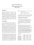
Performance Characteristics ......................................................................... 5
1.4.1
1.4.2
1.4.3
1.4.4
1.4.5
1.4.6
Correlation ................................................................................................ 5
Precision: Prothrombin Time (PT) ............................................................. 6
Precision: Activated Partial Thromboplastin Time (APTT) ......................... 7
Precision: Fibrinogen................................................................................. 7
Precision Factor X..................................................................................... 8
Precision: Factor IX................................................................................... 8
1.5
Front View KC4∆ Amelung ............................................................................ 9
1.6
Keypad ........................................................................................................ 10
1.7
Back View.................................................................................................... 11
1.8
Multipette ................................................................................................... 12
1.9
Thermal Printer (Optional) ........................................................................... 13
2. INSTALLATION..................................................................................................... 15
2.1
Unpacking ................................................................................................... 15
2.2
KC4∆ Startup Kit ......................................................................................... 15
2.3
Location Requirements................................................................................ 16
2.4
Electrical Requirements and Precautions.................................................... 16
2.5
Preliminary Check of Instrument Performance ............................................ 17
3. GENERAL OPERATION ....................................................................................... 19
3.1
KC4∆ Programs and their Function ............................................................. 19
3.2
Switching on the KC4∆ Coagulation Analyzer ............................................. 19
3.3
Temperature Indicator Screen..................................................................... 20
3.4
Main Menu Functions .................................................................................. 20
3.5
Configuration Menu Functions..................................................................... 21
3.6
Run Menu Functions ................................................................................... 23
3.6
Run Menu Functions ................................................................................... 23
3.7
Printer Menu Functions ............................................................................... 23
3.8
Reagent Handling........................................................................................ 24
3.9
Cuvette Preparation .................................................................................... 25
3.10 Sample Preparation..................................................................................... 26
3.11 Pipetting ...................................................................................................... 27
3.12 To dispense the Sample.............................................................................. 28
3.13 To Dispense the First Reagent.................................................................... 29
3.14 To Dispense the Starting Reagent .............................................................. 30
3.15 Selecting Operating Program and Starting .................................................. 31
3.15.1
3.15.2
3.15.3
Starting Routine or Single Test Program ..................................................31
Activating the Emergency Program ..........................................................32
Activating Test Mode Program .................................................................32
3.16 Operating Screen ........................................................................................ 32
O.M.V.1.1.2
07/03/30
1
0
3.16.1
3.16.2
3.16.3
Operating Screen in Routine and Single Test Program ............................32
Operating-Screen in Emergency Program................................................33
Operating Screen in Test Mode ...............................................................33
3.17 Sample Processing......................................................................................33
3.17.1
3.17.2
Starting Incubation Time ..........................................................................33
Testing.....................................................................................................34
3.18 Manual Measurement Abort.........................................................................35
3.19 Result Output...............................................................................................35
3.19.1
3.19.2
3.19.3
Result Output in “Test Mode” Program.....................................................35
Result Output in Routine, Emergency or Single Test ...............................35
Result Output to LIS (Laboratory Information System) .............................36
3.19.3.1
3.19.3.2
PC-SERIAL-Interface Specifications.................................................... 36
Data protocol for the PC SERIAL Interface.......................................... 37
4. PROCESSING MODE PROGRAMMING...............................................................39
4.1
Routine and Single Test Mode Programming ..............................................39
4.2
Emergency Program Programming .............................................................40
5. TEST CONFIGURATION/CHANGING CONFIGURATION ...................................43
5.1
Accessing Test Configuration ......................................................................43
5.2
PT, NT, TT ...................................................................................................44
5.3
PT (% activity) Flow Chart ...........................................................................47
5.4
RATIO..........................................................................................................48
5.5
Ratio Flow Chart ..........................................................................................49
5.6
INR (International Normalised Ratio) ...........................................................50
5.7
INR Flow Chart ............................................................................................52
5.8
APTT or TCT ...............................................................................................53
5.9
APTT Flow Chart (valid also for TCT)..........................................................54
5.10 FIB (Fibrinogen)...........................................................................................55
5.11 FIB Flow Chart.............................................................................................57
5.12 FAC (Factors) / FAC* (inverse Calibration Curve) .......................................58
5.13 FAC (Factors) Flow Chart ............................................................................61
6. QUALITY CONTROL.............................................................................................63
7. MAINTENANCE.....................................................................................................65
8. TROUBLESHOOTING...........................................................................................67
8.1
Troubleshooting Flow Chart.........................................................................67
8.2
Troubleshooting Procedures Table..............................................................67
A. APPENDIX .............................................................................................................73
A.1 INR Fast Track.............................................................................................73
A.2 APTT Fast Track..........................................................................................73
A.3 FIB Fast Track .............................................................................................74
A.4 FIB-Calibration Curve Dilutions....................................................................75
A.5 Extrinsic Factors II, V, VII und X Fast Track ................................................75
A.6 Extrinsic Factor Standard Curve Dilutions ...................................................76
A.7 Intrinsic Factors VIII, IX, XI und XII Fast Track ............................................76
A.8 Intrinsic Factor Standard Curve Dilutions ....................................................77
2
O.M.V.1.1.2
07/03/30
1
1.
Introduction
1.1
Intended Use
The KC4∆ Amelung is a semi-automated mechanical clot detection system designed for the
determination of prothrombin times (PT), activated partial thromboplastin times (APTT),
fibrinogen concentrations and other clotting tests. Any clotting time test that has fibrin formation
as its endpoint may be performed on the KC4∆. Measurement can be qualitative or quantitative.
When used in conjunction with appropriate reagents, the sample can be plasma or whole blood.
Addition of both sample and reagents is manual. The time measurement of the clotting endpoint
is automated.
1.2
Principle of Operation
The system utilizes a special cuvette in which there is a stainless steel ball. Sample is added to
the cuvette. After an appropriate incubation period, the cuvette is placed into the measuring well
of the KC4∆. The measuring well rotates slowly causing the cuvette to rotate along its
longitudinal axis. Because the cuvette is positioned at a slight angle, gravity and inertia always
position the ball at the lowest point of the cuvette. Exactly opposite the ball-position is a
magnetic sensor. With the addition of appropriate reagent, a timer is started. As coagulation
takes place fibrin strands form in the reaction mixture. The fibrin strands pull the ball away from
its inertia position that triggers an impulse in the magnetic sensor. This impulse electronically
stops the timer (see illustration).
Cuvette
Thermostatically
Controlled
Incubation
Block
Ball
Magnetic
sensor
Precision
Drive
Figure 1.1
O.M.V.1.1.2
07/03/30
3
1
1.3
Instrument Specifications
Type:
Coagulation Analyzer; Bench-top
Online:
Unidirectional
Principle:
Ball Method
Measuring Channels:
4
Display:
Liquid Crystal Display (LCD)
Incubation Wells:
8
Reagent Well:
5
Dimensions:
Height:
12 cm
Width:
35.4 cm
Depth:
45.0 cm
Weight:
6.3 kg
Power supply:
Primary Voltage:
100–240 V/50–60 Hz
Power Consumption:
1.5 A at 100 V; 0.4 A at 230 V
Measurement Time
4
Minimum:
4.5seconds
Maximum:
999.9 seconds
O.M.V.1.1.2
07/03/30
1
1.4
Performance Characteristics
The overall performance of any testing performed with the KC4∆ is not only dependent on the
instrument but is also a function of specimen collection, sample handling techniques and on the
accuracy and precision of the sample and reagent dispensing system used.
1.4.1
Correlation
The following linear regression data were obtained during evaluation to show equivalence with a
commercially available mechanical coagulation analyzer.
Prothrombin Time
APTT
121
110
Correlation Coefficient
0.998
0.896
Slope
1.051
1.235
Intercept
–0.241
0.873
Number
The following linear regression data were obtained during evaluation to show equivalence with a
commercially available photo-optical coagulation analyzer.
Fibrinogen
Factor X
Factor IX
109
112
101
Correlation Coefficient
0.930
0.974
0.897
Slope
1.067
1.010
0.958
Intercept
30.749
–0.166
3.403
Number
The following linear regression data were obtained in three physician's office laboratories (POL)
during evaluation to show equivalence with manufacturer derived results on the KC4∆
POL #1
Thromboplastin Time
APTT
Number
47
44
Correlation Coefficient
0.991
0.960
Slope
0.981
1.066
Intercept
0.492
0.379
POL #2
Thromboplastin Time
APTT
Number
45
46
Correlation Coefficient
0.989
0.965
Slope
1.019
1.029
Intercept
–0.248
1.021
O.M.V.1.1.2
07/03/30
5
1
POL #3
Thromboplastin Time
APTT
Number
52
47
Correlation Coefficient
0.974
0.927
Slope
1.012
0.786
Intercept
0.326
9.470
1.4.2
Precision: Prothrombin Time (PT)
Imprecision on the KC4∆ was evaluated at three levels according to the NCCLS EP5-T2
protocol.
Low
Mid
High
Mean
13.20
33.53
39.66
Total imprecision (CV %)
2.03
2.50
4.18
Within-run imprecision
1.02
1.28
1.53
PT total imprecision was evaluated at three physician's office laboratories at three levels
according to the NCCLS EP10-T protocol. Within-run imprecision (n = 20 on each level) was
evaluated at three physician's office laboratories at two levels.
POL # 1
Low
Mid
High
Total Mean
13.1
26.8
42.9
Total Imprecision (CV %)
1.97
1.63
2.47
Within-Run Mean
12.7
44.1
Within-Run Imprecision (CV %)
1.3
1.1
POL # 2
Low
Mid
High
Total Mean
12.1
23.3
40.7
Total Imprecision (CV %)
2.59
7.12
3.0
Within-Run Mean
12.1
41.7
Within-Run Imprecision (CV %)
2.6
1.8
POL # 3
Low
Mid
High
Total Mean
11.3
22.8
34.2
Total Imprecision (CV %)
1.57
7.41
0.50
Within-Run Mean
11.4
34.7
Within-Run Imprecision (CV %)
2.0
1.3
6
O.M.V.1.1.2
07/03/30
1
1.4.3
Precision: Activated Partial Thromboplastin Time (APTT)
APTT imprecision on the KC4∆ was evaluated at three levels according to the NCCLS EP5-T2
protocol.
Low
Mid
High
Mean
28.55
51.01
75.78
Total imprecision (CV%)
3.12
3.41
3.21
Within-run imprecision
1.47
1.60
1.37
APTT total imprecision was evaluated at three physician's office laboratories at three levels
according to the NCCLS EP10-T protocol. Within-run imprecision (n = 20 on each level) was
evaluated at three physician's office laboratories at two levels.
POL #1
Low
Mid
High
Total Mean
29.0
43.3
57.6
Total Imprecision (CV %)
2.83
3.15
1.87
Within-Run Mean
30.8
57.5
Within-Run Imprecision (CV %)
2.7
1.6
POL #2
Low
Mid
High
Total Mean
29.2
42.7
57.0
Total Imprecision (CV %)
4.38
2.29
2.84
Within-Run Mean
28.2
57.1
Within-Run Imprecision (CV %)
2.1
1.7
POL # 3
Low
Mid
High
Total Mean
30.0
54.7
68.6
Total Imprecision (CV %)
1.87
1.80
2.13
Within-Run Mean
26.9
64.4
Within-Run Imprecision (CV %)
1.4
2.5
1.4.4
Precision: Fibrinogen
Fibrinogen imprecision was evaluated at three levels according to the NCCLS EP5-T2 protocol.
Low
Mid
High
104.09
154.10
323.53
Total imprecision (CV%)
3.53
6.21
4.36
Within-run imprecision
2.05
2.86
2.12
Mean (mg/dl)
O.M.V.1.1.2
07/03/30
7
1
1.4.5
Precision Factor X
The imprecision was evaluated at three levels according to the NCCLS EP5-T2 protocol.
Low
Mid
High
31
57
102
Total imprecision (CV %)
8.28
5.71
5.22
Within-run imprecision
2.63
2.22
2.20
Mean (mg/dl)
1.4.6
Precision: Factor IX
The imprecision was evaluated at three levels according to the NCCLS EP5-T2 protocol.
Low
Mid
High
24
49
98
Total imprecision (CV %)
5.88
6.89
4.06
Within-run imprecision
3.96
4.04
2.54
Mean (mg/dl)
8
O.M.V.1.1.2
07/03/30
1
1.5
Front View KC4∆
∆ Amelung
3
2
4
5
6
1
7
Figure 1.2
Item
Function or Description
1.
Preparation area
Used for preparing samples before the
incubation step.
2.
Sample holders
Used for transferring cuvettes from preparation
area to reaction incubation wells and rotating test
positions.
3.
Reagent warming wells (5)
Three 15 mm, and two 11 mm heated used to
warm reagents.
4.
Pipette Tubes (2)
Used to store and preheat the pipettes when not
in use.
5.
Reaction incubation wells (8)
Heated wells used for incubation of sample and
first reagent.
6.
Rotating test positions (4)
Positions where start reagent is added and the
clotting time is measured.
7.
Display Screen
Displays incubation times, clotting times,
programming selections and other menus.
O.M.V.1.1.2
07/03/30
9
1
1.6
Keypad
1
2
3
4
6
4
4
4
5
12
13
6
6
11
7
10
9
8
Figure 1.3
Item
Function/Description
1.
START Key
Activates the automatic measurement timer
2.
Incubations Key
Starts the incubation timers
3.
READY Key
Skips the incubation time
4.
Channel Key
Activates the corresponding measuring channel
for incubation time, measurement or abort
5.
STOP Key
Interrupts measurement
6.
Function Keys
Used for programming or selecting tests
7.
MENU Key
Returns to Main Menu
8.
RUN Key
Returns to RUN menu
9.
↵
ENTER
10.
ESC Key
Cancels a function
11.
PRINTER Key (Printer/LIS)
Activates the output menu
12.
DILUTION Key
Used to change the patient dilution for the FIB
test (Section 5.10)
13.
DEL Key (Delete)
Deletes the previous entry
10
(Enter)
O.M.V.1.1.2
07/03/30
1
1.7
Back View
Figure 1.4
1
Item
2
3
6
4
5
Function or Description
1.
Label
2.
Automatic Multipette(s) sockets
Used to connect Multipipettes (remove the
cap plug in the Multipette)
3.
Power input
Used to connect the instrument to the
power supply
4.
Thermal printer port
Thermal printer connection
5.
Power switch
Powers the instrument ON/OFF
6.
Serial interface (RS232)
Used for transferring data to the LIS
(Laboratory Information System)
O.M.V.1.1.2
07/03/30
11
1
Multipette
1.8
1
4
1
3
5
6
7
8
9
2
Figure 1.5 Combitip
Item
Figure 1.6 Multipette
Function/Description
1.
Combitip
Tip used on the Multipette
2.
Combitip-aspiration/dispense cone
Portion of the tip that aspirates reagent.
3.
Combitip smallest pipetting volume
4.
Max. filling volume for the Combitip
5.
Locking Clamp
Used to firmly clamp the Combitip in the
Multipipette.
6.
Filling lever
The Combitip is filled by sliding the lever
upward.
7.
Dispense lever
The volume is dispensed by pressing the
dispense lever down until it stops
8.
Volume selection dial
Determines pipetting volume: setting (1-5)
multiplied by the minimum pipetting volume of
the Combitip (1.25 ml or 2.5 ml pipette tips).
9.
Start cable
Connects pipette to instrument.
Detailed instructions for the use of the Multipipette can be found in the Multipipette instruction
booklet.
Combitip and Multipette are trademarks registered by Eppendorf AG, Hamburg, Germany
12
O.M.V.1.1.2
07/03/30
1
1.9
Thermal Printer (Optional)
Figure 1.7
More detailed description and instructions for the use of the Thermal Printer can be found in the
Thermal Printer instruction booklet.
O.M.V.1.1.2
07/03/30
13
2
2.
Installation
2.1
Unpacking
The KC4∆ Coagulation Analyzer is shipped in a transport box designed to protect the instrument
from damage during shipment. If damage is apparent, immediately notify the shipping company.
Note the damage on the shipping bill of lading and notify your Trinity Biotech Sales
Representative.
2.2
KC4∆
∆ Startup Kit
Carefully remove the instrument and accessories from the transport box. Check that the
following items have been included:
►
KC4∆
∆
►
Power Supply and Power Cable
►
Starter-Set KC4∆
∆:
Catalogue #
Description
Quantity
Z04140
Tetravettes Micro Box with 150 pieces
1 Box
848040
Dust Cover KC4∆
1 each
832150
Tubes, Glass 14,5x85mm
50 each
832155
Tubes, Plastic 14,5x85mm
100 each
838012
Combitip 1,25ml
5 each
Additional Products and Consumables:
Catalogue #
Item
Z09165
Printer DPU 414-30B KC Delta
852015 *
KC∆ Series Thermal Printer Paper
P02100
KC4∆ Multipette with Starter Cable
838012 *
KC4∆ Combitips 1.25 ml
838025 *
KC4∆ Combitips 2.50 ml
838830
Pipette Delta 50/100/200µl
837045 *
Pipette Tips, Yellow, 200µl, 10 trays
832150 *
Tubes, Glass 14,5x85mm (50 pieces)
832155 *
Tubes, Plastic 14,5x85mm (100 pieces)
Z04140 *
Tetravettes Micro Box with 150 pieces
Z05111 *
KC Micro Cuvettes with Ball Dispenser
111028 *
KC Pipette Tube Sleeves
* These are consumable items and should be ordered as needed.
O.M.V.1.1.2
07/03/30
15
2
Pipettes are required for the test performance. Although the use of a Multipette will ensure the
start of the timing measurement is simultaneous with the addition of the reagent, it is not
mandatory.
Read the Operation Manual carefully prior to using the KC4∆
∆ Coagulation Analyzer. The
Operation Manual has been written to provide the most comprehensive understanding of the
operation of the KC4∆ Coagulation Analyzer and to enable you to fully utilize the features of the
instrument.
2.3
1.
2.
3.
2.4
Location Requirements
Place the KC4∆ Coagulation Analyzer on a stable, vibration and dust free work surface. It
should not be positioned next to a centrifuge or other equipment, which may cause
vibration. The KC4∆ Coagulation Analyzer should also be protected from moisture.
To avoid exceeding the control range of the instrument, place the KC4∆ Coagulation
Analyzer in an area with a maximum room temperature of 30°C. It should not be positioned
in an area directly below ventilating ducts which produce strong air currents. Do not expose
the KC4∆ Coagulation Analyzer to direct sunlight. Sunlight influences the temperature
control.
It is preferable to place the KC4∆ Coagulation Analyzer in an area which is no further than
(6 ft.) 1.8 m from an electrical outlet. The instrument should not be operated from an
extension cord which does not employ protective grounding. The electrical outlet used
should not be shared with any devices, which consume large amounts of power on a cyclic
basis (e.g., centrifuges, air conditioners, and refrigerators). When these type of devices
cycle on and off, there may be a voltage drop in the line which could interfere with the
proper functioning of the instrument.
Electrical Requirements and Precautions
The KC4∆ is connected to the mains power circuit by way of an external power pack. Using the
power pack connection cable connect the power pack to the KC4∆. Using the power supply
cable provided connect the power pack into the mains supply circuit.
1.
Do NOT use an extension cord not equipped to provide protective grounding.
2.
The KC4∆ is factory equipped with a three-pronged grounding plug designed to be
connected with a matching three-pronged receptacle. Under no circumstances should it be
connected to an ungrounded two-pronged plug. This procedure is in accordance with the
National Electrical Code and other applicable ordinances for this type of installation.
3.
It is recommended that a Trinity Biotech service representative perform any repair work
other than routine maintenance and minor adjustments.
4.
If instrument safety is uncertain the instrument may no longer be operated.
WARNING!
Use only the external power supply provided with the instrument
otherwise damage will be caused to the KC4∆.
16
O.M.V.1.1.2
07/03/30
2
2.5
Preliminary Check of Instrument Performance
The preliminary function checks of instrument operation should be performed prior to using the
instrument. This preliminary function check is to ensure that the instrument is functioning
properly prior to reporting patient results.
1.
Connect the power supply to the POWER SUPPLY socket on the back of the instrument
(DC6.5V 2A). Connect the power supply cable to the power supply and plug the power
cable into the electrical supply socket. A green light will shine on the power supply.
2.
Connect the Multipette Starter cables into the corresponding sockets (PIPETTES) on the
back of the KC4∆ instrument making sure that the Multipette locking mechanism is
securely seated.
Note:
3.
To protect the instrument from static electrical disturbance, some of the
connection sockets have protection caps. Please remove these caps before
connecting the peripheral equipment.
If the optional printer is being used connect the printer “SERIAL” input connector with the
printer port “PRINTER” on the KC4∆. Connect the printer to the mains supply circuit by
connecting the „POWER SUPPLY PRINTER” socket on the KC4∆ to the “DC6.5V 2A”
socket on the printer. Switch the printer on by sliding the “POWER” switch to 1.
Note:
In order to speed up the warming of the KC4∆ thermostatically controlled
measuring block, the power supply to the thermal printer will be activated when
the measuring block temperature has reached 35°C. The printer will then be
automatically switched on.
4.
Activate the KC4 ∆ Coagulation Analyzer by pressing the off/on switch located on the left
hand side of the back of the instrument.
5.
Observe that the display screen lights up. A screen showing a thermometer (see section
3.3) appears and will remain displayed while the instrument warms up to 35°C. Then the
display will switch to the Main Menu (se section 3.4).
6.
Observe that all four of the measurement wells are rotating. The wells will rotate
continuously whenever the instrument is on.
7.
Place a KC4∆ Micro cuvette or Tetravette into each position of the cuvette rack. Place the
cuvette rack on the rotating test positions such that the cuvettes are sitting flush in the
holes. If using a KC4∆ Micro cuvette, dispense one ball into each cuvette using the ball
dispenser. Observe that the ball falls to the front of the cuvette and stays there.
8.
Verification of temperature can be performed by placing approximately 3 ml of water into a
15-mm reagent tube. Place the reagent tube into the “Reagent warming wells” ( section
1.5.3). Place a thermometer into the tube and allow to equilibrate until the temperature has
stabilized. Approximately 15 minutes will be required for temperature stabilization. The
temperature should be 37.3° ± 0.5°C.
Note:
The use of smaller diameter tubes is not recommended due to inadequate
heat transfer. The thermometer should not drain heat from the measuring
medium (water). To verify the functionality of the sensors the Multipette® with the
starting cable should be used.
Note:
Settings made during the Performance Checks may vary from the previous
settings and may require that changes be made to the programming.
9.
In the Main Menu press <3> to enter the Configuration Menu.
O.M.V.1.1.2
07/03/30
17
2
10. Enter the password: default password is 1 2 3 4. Press <↵
↵>. The Configuration Menu will
display.
11. To select language press 5 Change language/ keypad.
12. Make an appropriate language and keypad assignment selection. Press <↵
↵>.
13. Press 3 Change Single test program; press TCT (Thrombin Clotting Time) key. Confirm
with <↵
↵>.
14. To access the program settings press <↵
↵>.
15. Press 1 (YES), to change the TCT settings.
16. Press 2 (duplicate testing) and “10” for the allowed CV; press <↵
↵>, to store entry and
continue.
17. Enter incubation time of “10” seconds. Press <↵
↵> to store entry and continue.
18. Press 2 (No). The settings will be stored.
19. Press <RUN>, to access the RUN Menu (see section 3.6).
20. Select 3 (Start single program).
21. Press the TCT (Thrombin Clotting Time). This activates the TCT-Test.
22. For Quantity (Samples per rack) press “2”. Then press<↵
↵> twice to bring up the operating
screen (see section 3.16).
and then all four
23. Activate all four incubation timers by pressing the Incubation Key
Channel Selection Keys . All four incubation timers run backwards from 10 (seconds) to
0. At “5”and “0” a beep tone will sound. The screen display „ *** in the Ready field
indicates that the incubation time has been completed.
24. When all incubation timers display “10”, press and hold the <START> key. Press the
dispense lever on the Multipette 4 times. Observe that beginning on the left all 4 measuring
channels will be activated. Release the <START> key.
25. After at least 10.0 seconds, remove the cuvette rack from the rotating test positions.
Observe that the timers stop and are indicating the elapsed time in seconds and tenths of
seconds. The *** in the Ready field will be replaced by ---.
26. If the optional printer is connected, after about 1 second the measurement timers will reset
to „0“ and the patient result protocol will be printed.
27. If the printer is not in use, not properly connected or not switched on, an error message will
be displayed: “Printer error”. Please check if the printer is properly connected and switched
on. Otherwise press <ESC>, to switch off the print program. The result protocol from the
first patient will be displayed on the screen. Press <↵
↵>, to scroll to the next result protocol.
Press <↵
↵>, to return to the Operating Screen.
With the completion of the Preliminary Checks of instrument Operation, installation is complete
and the KC4∆ instrument is ready for operation. If the instrument fails to perform any of the tests
with the specifications listed, call Instrument Service at Trinity Biotech
Note:
18
The settings for the TCT Test must be returned to the original settings (see
section 5.8).
O.M.V.1.1.2
07/03/30
3
3.
General Operation
3.1
KC4∆
∆ Programs and their Function
The KC4∆ coagulation analyzer has 4 different operation programs:
- Single Test Program
- Routine Program
- Emergency Program
- Test Mode
Program selection is made in the RUN Menu (see section 3.6).
Single Test Program: In the Single Test Program one programmed Test can be activated. All
samples will be processed using this test until the Single Test Program has been deactivated.
Patient IDs may be entered individually or counted upwards from a user definable starting
number. Tests result data will be processed according to the selected replicate configuration i.e.;
duplicate or single testing.
Routine Program: In Routine Program several different tests can be put together in a Test
Group. Each test will be processed as in the Single Test Program-one test on several patients.
To switch to the next test in the group press <↵
↵>. The next test in the Test Group will be
automatically activated. Patient IDs may be entered individually or counted upwards from a user
definable starting number. Tests result data will be processed according to the selected replicate
configuration i.e. duplicate or single testing. When the processing of the last test in the Test
Group is completed, select <↵
↵> to exit the Routine Program operation.
Emergency Program: In the Emergency Program several different tests will be allocated to
and processed from one patient. Tests result data for all tests in the Emergency Program will be
processed according to the selected replicate configuration i.e. duplicate or single testing. After
all tests have been completed the Emergency Program will be deactivated.
Test Mode: In this program selection defined test will not be processed and no IDs will be
allocated. Only time measurements are performed. No results will be transmitted to the printer or
to the LIS (Laboratory Information System). The measuring channels can be individually
activated. The incubation timers can be individually activated. The incubation timers will start at
“0” and be counted upwards by seconds.
3.2
Switching on the KC4∆
∆ Coagulation Analyzer
The KC4∆ Coagualtion Analyzer ON/OFF switch is on the back of the instrument (see section
1.7). Switch the instrument on. The 4 measuring channels will rotate and the display screen will
be activated.
O.M.V.1.1.2
07/03/30
19
3
3.3
Temperature Indicator Screen
After switching on the KC4∆, the temperature indicator screen will be displayed until the
thermostatically controlled measuring block has reached 35°C.
TRINITY
37°
BIOTECH
33°
29°
25°
21°
KC4
17°
DELTA
Version:
V2.3
Temperature-Display
In approximately 20 minutes the analyzer will reach operating temperature (37.3°C ± 0.5°C).
The display will change to the MAIN MENU:
3.4
Main Menu Functions
The Main Menu Screen will be activated using the <MENU> key. This is possible when no
measurements are currently being performed and no data entries have been made. The Main
Menu will also be automatically displayed after switching on the KC4∆ and attainment of a
measuring block temperature of >35°C.
Main Menu
-----------------------------Date:
Time:
1 Jan 2000
00:12
1
2
Configuration Menu
Print Parameters
RUN - Menu
3
4
RUN
Main Menu
Main Menu Functions:
Key
Function
<1>
Date entry: the new date will replace the old date.
<2>
Time entry: the new time will replace the old time.
<3>
Activates the Configuration Menu (see section 3.5).
<4>
If the optional printer is connected, selection of <4> will print out all the tests defined in
each of the processing options Routine, Emergency, Single and the settings of all
tests.
<RUN>
Note:
20
Activates the RUN Menu (see section 3.6)
When the KC4∆
∆ is switched off, the Date/Time and test settings will remain
active for approximately 2 weeks. If the instrument remains unused for
longer periods the test settings must be re-entered.
O.M.V.1.1.2
07/03/30
3
3.5
Configuration Menu Functions
The configuration menu is selected from the Main Menu (see section 3.4).
In the Main Menu press 3 Configuration Menu.
The Configuration Menu is protected from access by unauthorised personnel by a 4 digit
password. The default password is “1234”.
Enter the password and press the <↵
↵> key. (Incorrect entries can be deleted using the <DEL>
key.) The Configuration Menu will be displayed.
Configuration
routine
Change
emergency
Change
single
Delete
all
Change
language/keypad
5
Change
password
6
Press
ENTER
program
1
Change
program
test
prog.
programs
to
2
3
4
continue
Configuration Menu
1 Change Routine Program: (see also section 4.1)
This function allows the operator to select the tests available to be run in the Routine Program.
The tests are selected by pressing keys (INR, APTT, FIB, etc.) and confirming with <↵
↵>.
Incorrect entries may be corrected by pressing the <DEL> key. Terminating is possible with
<ESC>. Upon termination, the previously set values will remain valid. In this program, the
analyzer will allow a sequential operation of tests (Batch – mode).
2 Change Emergency Program (see also section 4.2)
This function allows the operator to select the tests available to be run in the Emergency
Program. The tests are selected by pressing keys (INR, APTT, FIB, etc.) and confirming with
<↵
↵>. Incorrect entries may be corrected by pressing the <DEL> key. Terminating is possible
with <ESC>. Upon termination, the previously set values will remain valid.
3 Change Single Test Program: (see also section 4.1)
This function allows the operator to individualize the test menu by sample if desired. The tests in
the Individual Program are chosen directly from the keyboard by pressing keys (INR, APTT,
FIB, etc) and confirming with <↵
↵>. Incorrect entries may be corrected by pressing the <DEL>
key. Terminating is possible with <ESC>. Upon termination, the previously set values will remain
valid.
Detailed information for modifying the processing options is described in section 4.
Note:
After selecting 1, 2 or 3 the Configuration Menu is exited by pressing ENTER or
ESC. Now the assay parameters can be defined or modified. These entered or
modified assay parameters definitions will be valid for all processing options. Only
the selected configuration of single/duplicate testing in the Emergency program
has priority over the assay definition replicate selection.
4 Delete All Programs:
The test selections for all of the processing options will be deleted. All assay definition settings
will also be deleted.
WARNING:
All tests in all processing options and all assay definition settings can be
deleted with one keystroke. A complete new installation of programs is
necessary if all programs are deleted.
O.M.V.1.1.2
07/03/30
21
3
5
Change Language / Keypad
After pressing <5> a new menu will be activated in which the languages German, English or
French may be selected. In the same menu the keypad options <PT> or <NT> and <Ratio> or
<TT> may be selected.
Language: By pressing <1> (GERMAN), <2> (ENGLISH) or <3> (French) the corresponding
language will be selected. The current selection is indicated by “*” after the number.
Keypad: By pressing the key <7> (PT und RATIO) or <8> (NT und TT) activates the keypad for
the corresponding tests. The current selection is indicated by “*” after the number.
Note:
If the keypad configuration is modified all tests selected for all processing options:
Routine, Emergency and Single Test Programs will be deleted (section 4). The
assay definitions will remain stored.
6 Change Password: The Configuration Menu is protected from interference by unqualified
personnel by a 4 digit password. The default password is “1234” and may be changed to a
laboratory-specific password. The default password is then invalidated. For that reason please
make sure that the new password does not get forgotten. Without the new password the
Configuration Program can no longer be accessed.
Press <ESC> during the new password entry and the old password will remain valid.
Change
New
Password:
Password
:
____
Press ENTER to
save new entry
Press
ESC
to
cancel
To change the password enter the new password (4 digits); press <↵>.
To confirm, re-enter the new password and complete the entry with <↵>. If both new password
entries were identical, the new password is now valid. If the new password entries were not
identical the old password remains valid.
Repeat the “Change Password” procedure if the error message “Incorrect Password” is
displayed.
22
O.M.V.1.1.2
07/03/30
3
3.6
Run Menu Functions
The Run Menu is activated by selecting the <RUN> key. Selection is only possible when the
measuring mode is not active or when no other actions have been activated
RUN-Menu
-----------------------------Start
routine
Start
emergency
Start
single
1
program
program
test
program
2
3
Test
mode
4
Main
menu
MENU
RUN-Menu
1 Start routine program:
The Routine Program is activated (sections 3.1 + 3.15.1)
2 Start emergency program: The Emergency program is activated (sections 3.1 + 3.15.2)
3 Start single test program:
The Single Test Program is activated (sections 3.1 + 3.15.1)
4 Test mode:
Clotting times will be measured using this program, without
using any of the pre-programmed test definitions
(see sections 3.1 + 3.15.3).
The Main Menu is activated (section 3.4)
MENU Main Menu:
Note:
3.7
When the measurement mode is inactive all programs can be exited using
the <RUN> or <MENU> keys.
Printer Menu Functions
The Printer Menu is activated by selecting the <Printer> key. Selection is only possible when
the measuring mode is not active or when no other actions have been activated
The currently selected options are flagged with “*”.
Data
report
Print
test
Enable
1
page
2*
printout
Disable
printout
3
Printout
incl.error
val.
4*
Printout
excl.error
val.
5
Printer
Press
installed?
ENTER
to
Ja
continue
Data Report
Key <1>: Using this selection, when the optional printer is connected a test-text will be printed.
The printer is correctly connected if this text is readable.
Key <2>: Using this selection results will be automatically printed, when the printer is correctly
connected. The result display on the KC4∆ screen will be deactivated. This selection must be
made every time the KC4∆ instrument is powered up. During active operation this function can
only be selected when the word “Yes” is displayed in the box beside the question Printer
installed?” (See below).
Key <3>: Use this selection to disable the automatic printout. Result data will be displayed on
the screen. Deferred printing of results is no longer possible.
O.M.V.1.1.2
07/03/30
23
3
Key <4>: If the KC4∆ is connected online to a Laboratory Information System (LIS, see section
3.18.3), use this selection to enable the transfer of data including error values (e.g. values
exceeding the max. CV)
Key <5>: Use this selection to enable the transfer excluding error values (e.g. values exceeding
the maximum CV).
The data transfer will be automatically performed at the completion of measurement and need
not be manually activated.
If the KC4∆ is not connected an LIS, Keys <4> and <5> have no function and any selection may
be made.
Printer installed?: When the printer is correctly installed, switched on and on-line, the box will
display “YES”. If “NO” is displayed the printer is either switched off, is off-line or the data line is
incorrectly connected.
3.8
Reagent Handling
Figure 3.1
Reagents for the appropriate test are prepared according to the manufacturer's instructions.
Refer to the manufacturer's reagent application for specific instructions on preparation and
handling of reagents. Any reagent requiring pre-heating should be placed into a 15-mm tube and
inserted into the reagent incubation well. The fluid level in the tube should not be above the top
edge of the incubation well. A minimum of 15 minutes will be required to warm reagent to 37.3°C
± 0.5°C.
Note:
If reagents are taken directly out of the refrigerator, they will need longer to
equilibrate.
All reagents should be used before the end of the manufacturer’s
recommended expiry date. Do not place open reagent vials on the
instrument!
24
O.M.V.1.1.2
07/03/30
3
3.9
Cuvette Preparation
ATTENTION!
The cuvettes are disposable and should not under any circumstances be reused.
ATTENTION!
Used cuvettes are potentially biohazardous.
Handle according to laboratory safety regulations for disposal of biohazardous
materials.
Unused cuvettes are not biohazardous.
ATTENTION!
After the cuvette carton has been opened the cuvettes and balls should be
protected from dust, humidity and any other dirt and should be stored according
the recommended storage conditions printed on the cuvette package.
Figure 3.2
In KC4∆ preparation area twelve (12) unheated
cuvette positions are available. Three (3) sample
holders each containing four (4) cuvettes may be
positioned there.
Place one Tetravette in the sample holder (see figure 3.2) and remove the paper ball retainer.
Unpacked cuvettes (bulk ware) may also be placed in the preparation area positions. The ball is
then added using the ball dispenser.
ATTENTION!
The operator must check that every cuvette positioned in the instrument contains
a ball.
O.M.V.1.1.2
07/03/30
25
3
Place the Tetravettes or Microcuvettes in the preparation positions. Up to twelve (12) cuvettes can
be positioned in the instrument at one time. The exact size and surface quality of the cuvettes is
critical to the proper performance of testing. Absolute cleanliness of cuvettes is mandatory for
correct performance. The cuvettes are intended as one-time use items.
Tetravettes are cuvettes in group in packs of four. Each cuvette contains a stainless steel ball
and can be used without any additional preparation.
The balls in the cuvettes are manufactured from a special stainless steel. Purity, weight, size,
surface quality and magnetic characteristics of the balls are all critical to the proper performance
of testing. The balls manufactured by Trinity Biotech have been tested to ensure compatibility
with the instrument measurement process and that they are inert when used with plasma and
coagulation reagents. Rust, slight impurities or oil residue can have a deleterious effect on
coagulation testing results. The balls are also one-time use items.
3.10
Sample Preparation
Plasma samples and reagents are added with appropriate microlitre pipettes. Refer to the
manufacturer’s reagent application to determine the sample and reagent(s) volume required for
each test. Pipetting technique is critical to the performance of testing. Refer to the Pipetting
section for guidelines in proper pipetting technique (section 3.11). Although the use of a
Multipette will facilitate initiation of measurement timing, special pipettes are not required. If a
Multipette is not available, measurement timing can be started using the start button and
channel buttons.
Sample is dispensed into the cuvette. Twelve o’clock is the recommended dispense position.
After sample has been dispensed, close the Plexiglas flap, pick the cuvette rack up and swirl
gently to evenly disperse the sample over the bottom of the cuvettes. Place the rack with
cuvettes in the rotating test positions ensuring that the cuvettes are pressed firmly down to the
bottom. Two additional racks of cuvettes (4 each) may also have samples pipetted and placed in
the reaction incubation wells.
Care must be taken not to over-incubate the samples. It is advisable to stagger the time interval
between the cuvette racks in the heated incubation wells and rotating test positions to prevent
over-incubation. Allow the samples to pre-incubate for the recommended time. It will take slightly
longer (a minimum of 120 seconds) for a sample that has been stored at refrigerator
temperature (2–8°C) to reach 37°C than for samples stored at room temperature (18–26°C).
Several of the coagulation factors, (Factors V, VIII, XIII, and fibrinogen) are labile at 37°C. To
avoid loss of these factors, samples should not be pre-incubated longer than 5 minutes.
Timing is critical in coagulation testing and the reagent manufacturer’s guidelines for incubation
times should be followed. Any particulate reagent must be well mixed prior to use. For those
tests having more than one reagent, all incubations prior to measurement start can be
accomplished in the reaction incubation wells. Nine o’clock is the recommended first-reagent
dispense position (section 3.13).
Care must be taken to avoid contact of the reagent pipette tip with previously dispensed sample.
After addition of reagent, close the Plexiglas lid, pick up the cuvette rack and swirl gently 5–6
times to mix the reagent and previously pipetted sample. The reaction mixture should be evenly
dispersed around the channel at the bottom of the cuvette. No more cuvettes should be
prepared for testing than can be completed within the specified guidelines.
In most instances, addition of a start reagent begins the coagulation process. It is important that
the Measurement Timer be started simultaneously to the addition of the start reagent in order
to ensure accuracy and precision of the assay. Test measurement timing can be started either
manually using the Channel Key or automatically by using the Multipette fitted with a starter
cable. Use of a Multipette will ensure that the reagent addition starts measurement timing.
26
O.M.V.1.1.2
07/03/30
3
The location of the start reagent dispense is important. To ensure that mixing of start reagent
with the previously pipetted sample or sample/reagent mixture begins immediately, the start
reagent should be dispensed just to the right side of the ball. This is best accomplished by
holding the pipette angled obliquely from the right rear side of the cuvette towards the ball
position and dispensing the reagent just to the right of the ball. Care must be taken to avoid
splashing the reagent out of the cuvette. The dispense rate should be of moderate speed and
forcefulness.
3.11
Pipetting
The overall performance of the KC4∆ Coagulation Analyzer is dependent on the accuracy and
precision of pipetting both sample and reagent(s).
Testing can be performed with either standard microlitre pipette(s) or with the Multipette fitted
with a starting cable. When the Multipette is used to dispense the final start reagent, the timer
is automatically started simultaneously with reagent dispense. When a standard microlitre
pipette is used for addition of the final start reagent, the timer is started manually using the
Specific Channel Key .
Regardless of what kind of pipette is used, the care taken with pipetting is directly proportional to
the overall accuracy and precision of testing.
To avoid contamination of reagents, if the same pipette is being used for both sample and
reagent, a new tip must be used when transitioning between sample and reagent.
To avoid cross-contamination between samples, a new tip should be used for each sample,
whether running plasma or whole blood samples.
Pipetting technique for non-repeating pipettes
To fill the pipette tip: Depress the button to the first stop. With the button depressed, insert the
tip into the sample or reagent to a depth of approximately 2–3 mm. If pipetting plasma directly
from a centrifuged tube of blood, the tip should be kept well away from the blood/plasma
interface. This will assure that no red cells or platelets will be aspirated into the tip. If pipetting a
particulate reagent, the reagent should be well mixed prior to aspiration.
Release the button slowly in such a manner that the sample or reagent flows smoothly into the
pipette tip. Slow aspiration will assure that the volume aspirated into the tip is accurate. If the
button is allowed to snap back, an incorrect volume may be aspirated. In addition, sample or
reagent can be aspirated into the barrel of the pipette. This can result in contamination of
subsequent samples or reagents. Unless the pipette is dismantled and cleaned, inadvertent
aspiration into the pipette barrel will result in eventual obstruction and incorrect operation of the
pipette.
Once the tip is filled, no dripping should be observed. If dripping is observed, either the tip is not
seated correctly on the pipette or the pipette requires maintenance. In such a circumstance,
replace the tip. If this does not correct the problem, the pipette should not be used until
maintenance can be performed.
Pipetting technique for Multipettes
Only pipette tips recommended for use with the pipette should be used. Any pipette tip whose
insertion opening is out-of-round should be discarded. Any pipette tips that are bent or otherwise
damaged should be discarded. The tip opening must not be occluded.
Slide the filling lever down until it stops, then raise the locking clamp upward.
Insert the Combitip until it clicks into position. Be sure the Combitip plunger is fully inserted
into the barrel before attaching it to the Multipette . Be sure the filling lever is completely down
and then lower the locking clamp to secure the Combitip in place.
O.M.V.1.1.2
07/03/30
27
3
Verify that the volume selection dial is set to dispense the correct volume. Immerse the
Combitip cone into the liquid. Fill by slowly sliding the filling lever upward. Wipe the Combitip
cone with a lint-free tissue. Follow the guidelines for correct dispense positions described in the
following sections.
3.12
To dispense the Sample
Sample should be dispensed to the 12 o'clock
position of the cuvette (See diagram). Aim the
pipette to the 12 o'clock position. Position the
tip approximately 3–4 mm above the bottom of
the cuvette. Depress the pipettor button to the
first stop and hold for 1–2 seconds to allow
the residual contents of the tip to collect at the
bottom of the tip. Press the button to the
second stop. This will deliver any residual
sample into the cuvette. To avoid bubbling
and splattering, the tip should not be placed
so close to the bottom that at the completion
of pipetting the tip is submersed in the
dispensed sample. An alternative method is to
touch the tip to the cuvette sidewall
approximately 3–4 mm above the bottom of
the cuvette and then depress the button
slowly to the first stop. Wait 1–2 seconds and
press the button to the second stop position.
Sample should not be dispensed by touching
the tip to the upper sidewalls of the cuvette.
Any sample that is left on the upper walls will
not participate in the coagulation reaction.
28
Pipet tip
Cuvette
Sample dispense
(12 o’clock)
Ball
(6 o’clock)
Figure 3.3
O.M.V.1.1.2
07/03/30
3
3.13
To Dispense the First Reagent
For those tests utilizing more than one reagent, the first reagent should be dispensed to the 9
o'clock position of the cuvette (See diagram). Aim the pipette to the 9 o'clock position. Position
the tip approximately 3–4 mm above the bottom of the cuvette. Depress the pipettor button to
the first stop and hold for 1–2 seconds to allow the residual contents of the tip to collect at the
bottom of the tip. Press the button to the second stop. This will deliver any residual reagent into
the cuvette. To avoid bubbling and splattering, the tip should not be placed so close to the
bottom that at the completion of pipetting the tip is submersed in the dispensed reagent. An
alternative method is to touch the tip to the cuvette sidewall approximately 3–4 mm above the
bottom of the cuvette and then depress the button slowly to the first stop. Wait 1–2 seconds and
press the button to the second stop position. To avoid contamination of reagent during
subsequent reagent pipetting, care must be taken to avoid contact of the tip with the previously
dispensed sample.
Pipet tip
Cuvette
Sample dispense
(12 o’clock)
First reagent
dispense
(9 o’clock)
Ball
Ball
First reagent
dispense
(9 o’clock)
Front view
Side view
Figure 3.4
O.M.V.1.1.2
07/03/30
29
3
3.14
To Dispense the Starting Reagent
The Start Reagent is the reagent that, when added, begins the coagulation reaction. Start
Reagent should be dispensed just to the right side of the ball. This positioning assures that
mixing of reagent with the other reaction constituents begins immediately. Holding the pipettor
obliquely from the right side, aim the pipette tip to the right side of the ball. Position the tip
approximately 5–6 mm above the ball. Depress the pipettor button to the last stop position. The
dispense rate should not be so rapid or forceful that reagent is splashed out of the cuvette. To
avoid contamination of reagent during subsequent reagent pipetting, care must be taken to
avoid contact of the tip with the previously dispensed sample and/or reagent. Refer to the
General Operation section for further information on the use of the automatic pipettor with starter
cable.
Pipet tips
Cuvette
Start reagent
dispense
(right side of ball)
First reagent
dispense
(9 o’clock)
Sample dispense
(12 o’clock)
Balll
(9 o’clock)
Front view
Side view
Figure 3.5
30
O.M.V.1.1.2
07/03/30
3
3.15
Selecting Operating Program and Starting
To activate the operating programmes bring up the RUN Menu (section 3.6) using the <RUN>
key.
Using the keys <1>, <2>, <3> or <4> select the desired program (section 3.1).
Note:
3.15.1
Before the Routine/Single Test/ or Emergency Programs can be activated,
the corresponding test must have been configured in the Configuration
Menu (see section 4 Mode Programming).
Starting Routine or Single Test Program
After selecting “Start Routine Program” or “Start
Single Test Program” you will be asked how
many samples are to be measured in one rack.
“Max” defines the maximum number of samples.
For singleton testing it is four (4), for duplicate
testing it is two (2) samples.
Enter the number of patients.
Note:
Use the key <↵> to set the number
to “Max”.
Test
XYZ:
Sample
per
Number:
Max = 2
Rack
?
Requesting the number of patients/rack
After entering the number of patients, you will be asked how the sample IDs are to be assigned.
There are two possibilities:
1)
Routine-Program
The sample ID will automatically incremented
by one beginning with the number displayed
in Patient ID:
Use key <1> to edit the starting number.
Press <↵> to activate this option.
Patient
Change
Manual
Press
2)
The sample ID can be individually defined:
Press key <2> to activate this option. Then
you will be asked for the sample IDs for the
first group of samples.
ID:
Start
input
enter
1
patient ID
of Pat.ID
to
1
2
continue
Requesting the Sample ID
Note:
The patient ID may have a
maximum of 9 digits.
Then the Operating Screen will be activated. Sample measurement can now begin (section
3.16.1).
Note:
If the patient ID is to be automatically incremented, the number of patients per
rack and patient IDs will not be requested. It is possible to change this by
selecting the corresponding test key (e.g. PT).
Note (only for Routine Program):
O.M.V.1.1.2
07/03/30
When processing of one for all samples has
been completed, press the <↵
↵> key to activate
the next test programmed in the Routine
Program.
31
3
3.15.2
Activating the Emergency Program
After selecting the “Start Emergency Program”
the patient ID will be requested.
Enter the patient ID and press the <↵> key.
Entry of up to 9 digits is permitted.
Stat
Patient
Press
entry
ID:
ENTER
?
to
save
new
The Operating Screen will be activated.
Requesting patient number
In the Operating Screen footer the test to be performed are displayed (section 3.16.2). If there
are more than 4 measurements to be performed the next ones will be called up when the first
measurements have been completed.
3.15.3
Activating Test Mode Program
After activating the “Test Mode” the Operating Screen will display (section 3.16.3). No additional
data entries are necessary. In this mode patient IDs are not allocated and only the time result
will be displayed on the screen. Result data cannot be transferred to the printer or to an LIS. The
measuring channels can be used independently of one another; this feature is unique to this
mode.
3.16
Operating Screen
All measurements are directed using the Operating Screen. The basic display configuration is
dependant on the active program e.g. patient number, test or patient number/rack.
3.16.1
Operating Screen in Routine and Single Test Program
Pat.ID:
1
FIB
Position
1
0
0.0
Inc. time
Meas.time
Start
2
3
0
0.0
0
0.0
1/10
4
0
0.0
Inc
Ready
1
2
3
4
left: ID of first patient
right: Test to be performed
Measuring channel positions 1 through 4
Incubation time in seconds
Measuring time in seconds
”***” Incubation time is running
“***” Measurement can be started or is running
”***” Measurement is complete
active channels with patient allocation
displayed: 4 different patients in single mode
e.g. four patients/rack in singleton
Pat.ID.:
Position
1
FIB
1
0
Inc. time
Meas.time 14.8
Start
Ready
2
3
0
9.3
0
0.0
***
***
Inc
--1
1
2
e.g. two patients/rack/duplicate testing
32
1/10
4
12
0.0
***
2
left: ID of first patient
right: Test to be performed
Measuring channel positions 1 through 4
Incubation time in seconds
Measuring time in seconds
”***” Incubation time ch. 4 running (12s left)
”***” Measuring channel 3 can be started
”***” Measuring channel 2 running (since 9.3s)
”***” Measuring channel 1 is done (Time: 14.8s)
active channels with patient allocation
displayed:
two different patients in
duplicate
O.M.V.1.1.2
07/03/30
3
3.16.2
Operating-Screen in Emergency Program
Pat.ID.:
123456
Position
1
Inc. time
Meas.time
Start
Stat
2
0
0.0
0
0.0
3
4
0
0.0
0
0.0
Inc
Ready
PT
FIB
1/10
TZ
left: patient number
right: Emergency Program
Measuring channels 1 through 4
Incubation time display in seconds
Measuring time display in seconds
”***” Incubation time is running
“***” Measurement can be started or is running
”***” Measurement in complete
active measuring channels with test allocation
displayed: three different tests in single mode
e.g. three test in Emergency Prog./singleton
Pat.Nr.:
123456
Position
1
0
Inc. time
Meas.time 15.1
Start
Stat
2
3
4
0
7.4
0
0.0
---
***
***
PT
PT
Inc
Ready
3
0.0
***
FIB
FIB
1/10 1/10
e.g. two tests in duplicate
3.16.3
Test
left: patient number
right: Emergency Program
Measuring channels 1 through 4
Incubation time display in seconds
Measuring time display in seconds
“***” Incubation time ch. 4 running (still 3s)
”***” Measuring ch. 3 can be started
”***” Measuring ch. 2 running (since 7,4s)
”---“ Measuring ch. 1 is complete, time: 15,1s
active measuring channels with test allocation
displayed: two different test in duplicate
Operating Screen in Test Mode
Mode
Position
T=
1
Inc. time
Meas.time
14
0.0
Start
***
Inc
Ready
2
3
0
0
0.0 12.3
***
1
37,3C
2
4
0
0.0
*** STOP
3
4
left: Program “Test Mode”
right: Measuring block temperature in [°C]
Measuring channels 1 through 4
Incubation time display in seconds
Measuring time display in seconds
“***” Incubation ch. 1 is running (since 14s)
“***” Measuring ch. 2 can be started
”***” Measuring channel 3 running (since 12,3s)
“STOP” Measuring on ch. 4 was interrupted
using the “STOP” key.
Test Mode – all 4 measuring channels are always
active
In the bottom left of the Operating Screen, the action selected using the
<START>, < > or <STOP> keys will be displayed (see section 3.17).
Note:
3.17
Sample Processing
3.17.1
Starting Incubation Time
1.
2.
After the measuring program has been selected the Operating Screen will be displayed.
With the transfer of the first rack to the rotating wells, press the Incubation timer . The
bottom left of the Operating screen will display “START Inc” confirming that the incubation
procedure has been initiated.
Start the incubation timers for each channel which is activated in the lower part of the
Operation Screen and which contains a sample to be tested.
O.M.V.1.1.2
07/03/30
33
3
3.
4.
Press the Channel timer key . The “Start Inc” field will display “***” for the corresponding
channels. At the same time each of these channels will begin the incubation countdown,
starting with the incubation time defined for this test.
Exception: In measuring program “Test Mode” the incubation time will counted upwards.
When the desired incubation time has been reached, press the <READY> key and then the
Channel Timer key
to activate the channel.
When 5 seconds of the incubation time remain an audible beep will sound. The *** flag will
be moved from the “Start Inc.” field to the “Ready” field. When the Ready field is so flagged
that channel may be started.
Note:
3.17.2
1.
2.
3.
4.
5.
Each channel may be started without an incubation time. However, the operator
should adhere to the manufacturer’s recommendations for the test procedure. To
override or interrupt the incubation time, press the <READY> key and then the
corresponding Channel Timer
key. The selection of the <READY> key will be
confirmed with “READY” in the bottom left of the Operating Screen.
Testing
Install an appropriately sized tip onto the pipette.
Mix particulate reagent by covering the tube with Parafilm® and inverting gently. Do not
shake. Many coagulation reagents are mixtures of lipids, which will undergo spatial
rearrangement when shaken.
Aspirate reagent into the pipette tip. Dispense one aliquot of reagent into reagent container
to prime the pipette tip.
Press the <START> key.
Dispense reagent just to the right side of the ball and simultaneously press the Specific
Channel Key.
There are two starting methods: Automatic (recommended) and the Manual start method.
Automatic Start Procedure
The KC4∆ Multipette is recommended for use in the Automatic Start Procedure.
Assure that the Multipette cable is plugged into the Automatic Pipette socket located on
the rear of the KC4∆ Coagulation Analyzer. Up to three pipettes may be installed.
Press and hold the <Start> key during reagent dispense into the measuring channels. The
reagent is dispensed from left to right, starting with Channel 1. Simulateously with the
reagent dispense the timers will start counting- The next measuring channel to the right will
be set for measurement start. It will be started simultaneously with the next reagent
dispense and the following channel to the right will be set for measurement start.
If the operator releases the <START> key after the reagent is added to the first cuvette, it
must be pressed before the addition of reagent to each cuvette.
Confirmation that the <START> key has been selected is confirmed by the display “Start
Meas.” in the bottom left of the Operating screen.
Manual Start Procedure
The manual start procedure is used when no pipette with starting cable is available. Press
the <START> key. As a control the lower left field will display “Start Meas”. Simultaneously
with the dispensing of the start reagent the measurement timers must started. Therefore
press the Channel Key
simultaneously with start reagent dispense. The measurement is
started and the measurement timers beginns running.
Replace the pipette in the heated pipette sleeve.
34
O.M.V.1.1.2
07/03/30
3
Replace the pipette tube holder sleeves daily and for each new reagent.
Pipette tube holder sleeves should be treated as biohazardous waste.
With the addition of start-reagent, initiation of the coagulation process begins. As
coagulation takes place, fibrinogen polymerizes to form strands of fibrin. The formed fibrin
sweeps the ball out of its steady position, which triggers an impulse in the magnetic sensor.
This impulse electronically stops the timer signifying the end of measurement time. The
“Ready” field will display “----“. Measurement has been completed. The elapsed time will
be displayed in seconds and tenths of seconds. When all tests have been completed, the
actual results will be calculated.
Note:
3.18
Manual Measurement Abort
If a measurement has to be manually aborted because no clot has formed or because a test was
incorrectly started press the <STOP> key. In the bottom left of the Operating Screen “STOP” will
be displayed confirming that the stop procedure has been initiated. Press the corresponding
Channel timer key
to stop the measurement in that channel. “STOP” will display in the
corresponding position in the Operating Screen. No result will be calculated for this
measurement.
If more patients/rack were selected than will actually be measured, then these can be aborted
without starting.
If patient numbers are set to automatically increment, patient number will still be allocated even
for aborted measurements.
3.19
Result Output
3.19.1
Result Output in “Test Mode” Program
If measurements are performed using the Test Mode program, only the measurement timer will
be stopped. The measuring time can be read off the Operating Screen. There will be no
calculation of raw data, transfer of data to the printer or transfer of data to the LIS interface.
3.19.2
Result Output in Routine, Emergency or Single Test
Results will be automatically calculated and released when all activated measurements have
been completed. Activated measuring channels are indicated by a number or a test code in the
bottom line of the Operation Screen (section 3.16). If a measuring channel does not conclude a
measurement while e.g. no clot is formed, then the measurement must be manually aborted
(see section 3.18)
Result Output with Optional Printer
If the printer has been correctly installed (see section 1.10 +2.5.3) the raw data and calculated
results will be transferred to the printer and printed. These results will not be displayed on the
Operating Screen. New measurements can be performed on the KC4∆ coagulation analyzer
during the printing of results.
O.M.V.1.1.2
07/03/30
35
3
Example:
Result Output with Printer
---------------------------------------------------------05 Feb 2004 10:34
Single Test Program: PT
Patient ID: 123456
Measured values:
11.9 sec
12.1 sec
Average value:
12.0 sec
Difference:
0.8%
Result:
108.3%
INR:
1.17
---------------------------------------------------------Note:
The end of the paper roll is indicated with red diagonal stripes. When these
stripes are visible insert a new roll of paper.
Result Output without the Optional Printer
The KC4∆ coagulation analyzer default settings presume that the optional printer will be
installed (see section 1.10). The first attempt to transfer data and results to the printer will
provoke the screen display: “Printer error! Please check if printer is installed correctly and
switched on. Or press ESC to disable printout.” Press the <ESC> key and the error message will
be deleted.
The raw data and calculated results for each patient – or in Emergency program each test – will
now be displayed on the KC4∆ screen. Press the <↵
↵> key to scroll to the next result.
After the last result has been displayed press the <↵
↵> to perform more tests in the Routine or
Emergency Program.
If all tests in the Emergency Program have been performed, the Emergency Program will be
deactivated after the last Emergency result has been displayed.
3.19.3
Result Output to LIS (Laboratory Information System)
Simultaneously with the output of result data to the display or the printer, the data will also be
transferred to the LIS interface. It is an RS232 interface, and is on the back of the KC4∆ labelled
with „PC Serial“. If this interface is not being used, there is nothing which needs to be observed
or set. If the interface is to be used it is possible to select if results with error flags are to be
transferred or not (section 3.7)
3.19.3.1
PC-SERIAL-Interface Specifications
► Baud rate 9600 Bit / sec
► Complete ASCII Character Set
1 Start-bit, 7 Information bits (Bit 1-7), odd or even parity, (parity-disabled) or 8 Bit without
parity, 2 Stop bits
► 9 pin Sub D-Connecter DB9
Pin 2 = RXD
Pin 3 = TXD
Pin 5 = GND
36
O.M.V.1.1.2
07/03/30
3
3.19.3.2
Byte
↓ 1
2
3
4
5
6
7
8
9
10
11
12
13
14
15
16
17
18
19
20
21
22
23
24
25
26
27
28
29
30
31
32
33
34
35
36
37
38
7
0
Data protocol for the PC SERIAL Interface
6
0
5
0
4
0
3
0
2
0
1
1
0 Bit
0
STX
Program
0
0
1
0
0
0
0
0
Blank
ID-No.
(Patient
number)
0
0
1
0
0
0
0
0
0
1
0
0
0
0
0
0
0
1
0
0
0
0
0
0
1
0
0
0
0
0
1
2
.
3
Right justified
1
2
3
.
4
Right justfied
If value 2 missing ,
will be filled with “X”
1 2
1 2 3
1 2 .
1
.
.
3
0
3
4
4
0
12.3
123.4
12.34
100
space
1
2
.
3
Right justfied
Example of unit
space
%
left justified
space
spaceLeerzeichen
0
1
0
0
0
0
0
Blank
0
0
1
0
0
1
0
0
0
0
1
0
0
0
1
0
Fehler (E)
E
With error “ E ”,
no error “ Blank ”
40 0
41 0
42 0
0
0
0
0
0
0
0
0
0
1
1
0
1
0
0
0
1
1
1
0
1
CR
LF
ETX
CR
LF
ETX
Carriage return
Line feed
End of text
O.M.V.1.1.2
07/03/30
(When a PT-/NT- o. TT-Test
with INR is performed, the
complete data protocol will be
transmitted twice:
The first time for the PT/NT or
TT Test,
The second time for the INR
Test)
Example of value and result
0
39
APTT
PT
RATIO
Right justified
space
Blank
Einheit
Left justified
A P T T
P T
R A T I O
Space
Blank
Ergebnis
0
1
2
3
4
5
6
7
Blank
Value 2
[Sec.]
Example for program
Start of text
Space
Blank
Value 1
[Sec.]
0
Example
STX
A
P
T
T
%
G L
S
%
g/l (Grams per Litre)
s (Seconds)
37
4
4.
Processing Mode Programming
4.1
Routine and Single Test Mode Programming
Programming the Routine Program defines the tests which are to be performed in the Routine
Program mode (section 3.1)
Programming the Single Test Program defines which tests can be called up and performed in
the Single Test Program mode (section 3.1).
The programming method for both the Routine and Single Test Program is the same.
Main Menu
Activate the Main Menu using the <MENU> key (see
section 3.4)
Main
Date:
Select <3> Configuration Menu.
Menu
-----------------------------1
Time:
Jan
1
2000
00:12
2
Configuration
Print
menu
3
paramters
4
RUN-Menu
RUN
Screen Password Entry
Enter the password and press ENTER <↵
↵>.
Enter
password:
Press
ENTER
____
(The default password is 1234)
to
continue
Configuration Menu
Select
1 Change Routine Program, if the Routine program is
to be programmed.
3 Change single test program if the Single Test
Program is to be programmed.
Configuration
O.M.V.1.1.2
07/03/30
1
routine
Change
emergency
Change
single
Delete
all
Change
language/keypad
5
Change
password
6
Press
For Routine Program programming
Select all of the tests which will form the Routine Program
test group using the appropriate function keys (e.g.
<APTT>). The tests will be processed in the “RUN” mode
in the same order they have been selected. Wrong entries
can be deleted using the <DEL> key. If programming is
aborted using the <ESC> key, the test programmed in the
original Routine Program will remain active. When all
tests have been selected, press <↵
↵> to return to the
Configuration Menu.
Menu
Change
program
2
program
test
prog.
3
programs
ENTER
to
4
continue
Example: Routine-Program
Tests
in
Routine
APTT
program:
FIB
TZ
INR
Press ENTER to
save new entry
Press
ESC
to
cancel
39
4
For Single Test Program programming
Using the appropriate function keys (e.g. <APTT>), select
all of the tests which should be available in the Single
Test Program mode. Wrong entries can be deleted using
the <DEL> key. If programming is aborted using the
<ESC> key, the test programmed in the original Single
Test Program will remain active. When all tests have
been selected, press <↵
↵> to return to the Configuration
Menu.
Example: Single Test Program
Tests
in
Routine
APTT
program:
FIB
TZ
INR
Press ENTER to
save new entry
Press
ESC
to
cancel
Configuration Menu
If the Configuration Menu is exited using the <↵
↵> key, all
of the programmed tests and their parameters will be
displayed in sequence. Test parameters can be entered
or changed during this sequence (section 5).
Note:
4.2
The test parameters will always be
displayed when the Configuration Menu is
exited if at least one of the three menus
“Change xxx program” is selected.
Configuration
Menu
routine
Change
emergency
Change
single
Delete
all
Change
language/keypad
5
Change
password
6
Press
program
1
Change
program
test
prog.
programs
enter
to
2
3
4
continue
Emergency Program Programming
Programming the Emergency program defines which tests will be processed in the Emergency Program
(section 3.1)
Main Menu
Activate the Main Menu using the <MENU> key (see
section 3.4). Select <3> Configuration Menu.
Main
Menu
-----------------------------Date:
1
Time:
Jan
2
Configuration
Print
1
2000
00:12
Menu
3
parameters
4
RUN-Menu
RUN
Screen Enter Password
Enter the password and press ENTER <↵
↵>.
Enter
password:
Press
ENTER
____
(The default password is 1234)
to
continue
Configuration Menue
Press
2 Change Emergency Program.
Configuration
Change
emergency
Change
single
Delete
all
Change
language/keypad
5
Change
password
6
enter
program
1
routine
Press
40
Menu
Change
program
test
prog.
programs
to
2
3
4
continue
O.M.V.1.1.2
07/03/30
4
Using the appropriate function keys (e.g. <INR>) select all
of the tests which should be available in the Emergency
Program mode. The tests will be processed in the “RUN”
mode in the same order they have been selected.
Wrong entries can be deleted using the <DEL> key.
If programming is aborted using the <ESC> key, the test
programmed in the original Emergency Program will
remain active. When all tests have been selected, press
<↵
↵>.
Example: Emergency Program
Tests
in
Emergency
INR
program
TCT
Press ENTER to
save new entry
Press
ESC
to
cancel
Singleton or duplicate testing
All tests in the Emergency Program will be processed
either in single (key 1) or duplicate (key 2)
in
Emergency
Single
program
test
Press the <↵
↵> key to retain the current setting.
Change?
Note:
The selection of single or duplicate testing
made for tests in the other processing
modes are not valid for the Emergency
Program (see section 5).
Single
Press
1
test
Duplicate
ENTER
test
to
2
continue
Enter difference
When duplicate testing has been selected the maximum
permitted difference between duplicate measuring times
in [%] must be entered. Press <↵
↵> to close.
If the entry is aborted using the <ESC> key, the currently
programmed maximum difference value will be retained.
The difference is calculated as follows:
in
Emergency
Max.
program
Difference(%):
0
Press ENTER to
save new entry
Press
ESC
to
cancel
Difference(%) =(difference between measuring and average value) x100
Average Value
Configuration Menu
The Configuration Menu will be activated.
If the Configuration Menu is exited using the <↵
↵> key, all
of the programmed tests and their parameters will be
displayed in sequence. Test parameters can be entered
or changed during this sequence (section 5).
Configuration
Change
Emergency
Change
Single
Delete
all
Change
language/keypad
5
Change
password
6
O.M.V.1.1.2
07/03/30
ENTER
Program
1
Routine
Press
Note:
Menu
Change
program
test
prog.
programs
to
2
3
4
continue
The test parameters will always be displayed when the Configuration Menu
is exited if at least one of the three menus “Change xxx program” is selected.
41
5
5.
Test Configuration / Changing Configuration
Prerequisite
In order for a test to be configured it must have been selected for use in at least one of the
processing programs (see section 4).
If this is not the case, insert the test in one of the processing programs. Please note that the
insertion of a new test in a processing program will deactivate the previous programming. The
originally programmed test must be reselected by pressing the corresponding function key (e.g.
INR). In the Routine and Emergency Program the order of entry is important. Tests will be
processed in the same order that they are entered in these programs.
Configuring a Test or changing a test configuration
In order to change test parameters at least one of the menu options “Change Routine”,
“Emergency” or “Single Test Program” must be selected from the Configuration Menu
(section 4). The menu option “Change XXX program” can be exited using the <ESC> key. The
program retains the original settings. The Configuration Menu will be recalled. After pressing the
<↵
↵> key all of the tests and specific test programming will be displayed in sequence and may be
changed. Any changes to the test configuration made here will be valid for all processing
programs except the definition single/duplicate testing in the Emergency Program (section 4.2:
max. difference entry).
5.1
Accessing Test Configuration
Press the <MENU> key to activate the Main Menu
(section 3.4)
Main
Date:
1
Time:
Select <3> Configuration Menu.
Menu
-----------------------------Jan
2
Configuration
Print
1
2000
00:12
menu
3
parameters
4
RUN-Menu
Enter the password:_ _ _ _.
RUN
Enter
password:
Press
ENTER
____
(The default password is 1234)
Press the <↵
↵> key.
Select one of the menu options:
Routine, Emergency or Single Test Program using keys
<1>, <2> or <3>
(Example: 3 „Change Single Test Program“)
O.M.V.1.1.2
07/03/30
to
Configuration
continue
Menu
Routine
Change
Emergency
Change
Single
Delete
all
Change
language/keypad
5
Change
password
6
Press
ENTER
Program
1
Change
program
test
prog.
programs
to
2
3
4
continue
43
5
Abort programming using the <ESC> key. The original
programming will be retained and the Configuration Menu
recalled.
Tests
in
Single
INR
program
TCT
FIB
Press the <↵
↵> to exit the Configuration Menu.
All of the tests which are programmed in at least one of
the proceeding programs will be displayed in sequence.
Tests may now be configured by pressing <1> “Modify?
Yes”. The configuration description will be described
under the corresponding name in the following sections.
Press ENTER to
save new entry
Press
ESC
to
cancel
If the parameters are correct press <↵
↵> or <2> “Modify? No” and the parameters of the next test
will be displayed.
When the last test has been displayed the Main Menu will be displayed. The configuration is
complete.
5.2
PT, NT, TT
PT: Thromboplastin Time or Prothrombin time
NT: Normotest™
TT: Thrombotest™
The method of configuration of the tests PT, NT and TT is the same. For example the PT test
will be described.
Dependant on the keypad setting (section 3.5.5) the tests PT and RATIO or NT
und TT can be activate.
The following values are only examples. The correct values should be taken from the reagent
manufacturer’s test application.
Note:
Call up the test configuration (section 5.1) and test PT. Following display will appear on the
screen.
Select YES <1>, to change the settings.
Select No <2> or <↵
↵> to retain the original settings. The
configuration for the next test will be displayed.
Test
Incubation time
Single test
Calibration cur
Point 1: 0,0%
Point 2: 0,0%
Point 3: 0,0%
PT max. :
0%
Without
INR
Change?
Test:
PT:
(Sec
:
ve
= 0,0
= 0,0
= 0,0
0
Sec
Sec
Sec
calculation
Yes
No
1
2
PT
Single
test
For Singleton testing select <1> Single Test.
To perform the test in duplicate select
<2> Duplicate Test.
Change?
If <↵
↵> is selected the original setting will be retained.
Press
Single
1
test
Duplicate
ENTER
2
test
to
continue
Thrombotest is a trademark registered by Axis Shield PoC as, Norway
44
O.M.V.1.1.2
07/03/30
5
If duplicate test is selected enter the max. difference
(%CV) and press <↵
↵> to save the new entry.
Press <ESC> to retain the original setting.
Test:
Max.
PT
Difference(%):
5
The difference will be calculated as follows:
Difference(%)=(Difference between Measuring and Average time)x100
Average Value
Enter the incubation time defined in the test application
and press <↵
↵> to save the new entry.
Press <ESC> to retain the original setting.
Press ENTER to
save new entry
Press
ECS
Test:
PT
to
Incubation
cancel
time(Sec)
:
60
Press ENTER to
save new entry
Press
Enter the reference values for the PT calibration Curve.
Point 1 is the point with the highest value and the shortest
time. The value need not be 100%. It may vary according
to the source of the reference plasma.
Example: 100 %
to
cancel
Calibration
curve
Point
:
1
(%)
PT:
100,0
Press ENTER to
save new entry
Press
Enter the clotting time for the first point on the PT
calibration curve and press <↵
↵> to save the new entry.
ESC
ESC
to
Calibration
Point
1
cancel
Curve
(Sec):
PT:
10.8
Press <ESC> to cancel and retain the original setting.
The value of point 1 is the one with the shortest value.
Example: 10.8 seconds
Press ENTER to
save new entry
Press
Enter the second value for the PT calibration curve and
press <↵
↵> to save the new entry.
ESC
to
Calibration
Point
2(%)
cancel
curve
:
PT:
50.0
Press <ESC> to cancel and retain the original setting.
The second point is a reference plasma dilution.
Press ENTER to
save new entry
Example: 25 %
Press
Enter the clotting time for the second point on the PT
calibration curve and press <↵
↵> to save the new entry.
Calibration
Point
ESC
2
to
cancel
curve
(sec):
PT:
25.6
Press <ESC> to cancel and retain the original setting.
Example: 21.5 seconds
Press ENTER to
save new entry
Press
O.M.V.1.1.2
07/03/30
ESC
to
cancel
45
5
Enter the third value for the PT calibration curve and
press <↵
↵> to save the new value.
Press <ESC> to cancel and retain the original setting.
The third point is the lowest point in the curve and is a
reference plasma dilution.
Example: 12.5 %
Enter the clotting time fort he third point on the PT
calibration curve and press <↵
↵> to save.
Calibration
Point
3(%)
curve
:
PT:
12.5
Press ENTER to
save new entry
Press
ESC
to
Calibration
Point
cancel
curve
3(sec):
PT:
31.4
Press <ESC> to cancel and retain the original setting.
The value for point 3 is the one with the longest time
value.
Press ENTER to
save new entry
Press
ESC
to
cancel
Example: 31.4 seconds.
Enter the maximum value to be reported for the PT in %
and press <↵
↵> to save the new entry.
Press <ESC> to cancel and retain the original setting.
Values which are higher than the defined PT max. will not
be evaluated and is reported as “> defined PT max.
value”.
Calibration
curve
PT
130.0
max:(%):
PT:
Press ENTER to
save new entry
Press
ESC
to
cancel
Example: 130 %
If the INR is to be calculated, the ISI value must be
entered. Press <↵
↵> to save the new entry.
The standard value does not need to be entered. It will be
calculated from the calibration curve.
If the ISI value “0“ is entered no INR value will be
calculated.
Calibration Curve
Calculate INR
W
e
W
e
i
n
i
n
ISI
t
t
t
t
PT
h INR calculation
er ISI value
hout INR calculation
er ISI value = 0
value:
1,03
Press ENTER to
save new entry
Press
ESC
to
cancel
Press <ESC> to cancel and retain the original setting.
Example: 1.03
In conclusion all values will be displayed.
If the values have been correctly entered complete the
entry with No <2> or <↵
↵>.
The PT test is configured.
All parameters of the following tests are now displayed. If
there are no tests to follow the Main Menu will be
activated.
Test
PT:
Incbation time(Se
Single test
Calibration curve
Point 1: 100,0%
Point 2:
25,0%
Point 3:
12,5%
PT max. :
130%
c
=
=
=
:
60
10,8
21,5
31,4
With INR calcualtion
ISI value
: 1,03
Change?
Yes 1
No
Sec
Sec
Sec
2
If incorrect values have been entered, press Yes <1> to repeat the data entry routine.
46
O.M.V.1.1.2
07/03/30
5
5.3
PT (% activity) Flow Chart
Test PT:
Incubation time(sec):: 0
Inkubationszeit(Sek)
Einzelbestimmung
Single
test
Eichkurve
Calibration
curve
Punkt 1:
Point
0,0% = 0,0 Sec
Sek
Punkt 2:
Point
0,0% = 0,0 Sec
Sek
Punkt 3:
Point
0,0% = 0,0 Sec
Sek
PT max. : 130%
140%
No
Ohne INRINR
Without
Berechnung
calculation
!
Ja 1
Yes
Aendern??
Change
Nein
No
2
YES
Test
PT
Einzelbestimmung
Single
test
Nächster
Next
testTest
or main Menu
Aendern?
Change?
Einzelbestimmung
Single
test
1
Doppelbestimmung
Duplicate
test
2
Weiterenter
Press
mit Taste
to continue
ENTER
Single test
Duplicate test
Calibration
Eichkurve
PT:
curve
INR berechnen
Calculate
INR ?
Test: PT
WithINR
Mit
INRBerechnung
calcualtion
Enter
INR Value
ISI - Wert
eingeben
Ohne INRINR
Without
Berechnung
calculation
ISI - Wert
Enter
ISI Value=
= 0 eingeben
0
Max. Difference(%):
Differenz(%) : 10
ISI - Value
Wert
:
5,00
1,03
PressEingabe
Neue
ENTER to
speichern
mit Taste
save
new entry
ENTER
Abbruch
Press
ESC
mit
toTaste
cancel
ESC
PressEingabe
Neue
ENTER to
speichern
mit Taste
save
new entry
ENTER
Abbruch
Press
ESC
mit
toTaste
cancel
ESC
Test: PT
Eichkurve PT:
Calibration
curve PT
Inkubationszeit(Sek)
Incubation
time(Sec)::60
60
PT max(%) : 130
140
PressEingabe
Neue
ENTER to
speichern
mit Taste
save
new entry
ENTER
PressEingabe
Neue
ENTER to
speichern
mit Taste
save
new entry
ENTER
Abbruch
Press
ESC
mit
toTaste
cancel
ESC
Abbruch
Press
ESC
mit
toTaste
cancel
ESC
Eichkurve PT:
Calibration
curve
Eichkurve PT:
Calibration
curve PT
Punkt 1 (%) : 100,0
Point
PressEingabe
Neue
ENTER to
speichern
mit Taste
sane
new entry
ENTER
Abbruch
Press
EXC
mit
toTaste
cancel
ESC
Note:
O.M.V.1.1.2
07/03/30
For points
1-3
repeat
Punkt 1 (Sec
Point
(Sek)::12,0
12,0
PressEingabe
Neue
ENTER to
speichern
mit Taste
save
new enrtry
ENTER
Abbruch
Press
ESC
mit
toTaste
cancel
ESC
The flow chart can also be used for NT and TT.
47
5
5.4
RATIO
Depending on the keypad settings (see section 3.5.5), the tests PT and RATIO or
NT and TT may be activated.
The following values are only example values and should be replaced by the values given in the
test application.
Call up the test configuration and the RATIO test (section 5.1.). Following will be displayed on
the screen.
Note:
Test
Select Yes <1>, to change the settings.
Incubation
Press No <2> or <↵
↵> to retain the original settings. The
next test will be displayed for configuration.
Mean
time(sec):
Normal
Single
test
Change
?
For single testing, select <1> Single test.
For duplicate processing, select <2> Duplicate test.
Test
Press <↵
↵> to cancel and retain original setting.
Change?
Single
The difference will be calculated as follows:
Difference(%)=(Difference between Measuring and Average value)x100
Average value
Enter the incubation time defined in the test application
and press <↵
↵> to save the new entry.
Press <ESC> to cancel and retain the original settings.
Enter the Mean normal value in seconds and press <↵
↵>
to save the new entry.
Press <ESC> to cancel and retain original settings.
2
No
test
1
test
Press
ENTER
Test:
RATIO
2
test
to
continue
Difference(%):
5
Press ENTER to
save new entry
Prees
ESC
Test:
RATIO
to
Incubation
cancel
time(Sek)
:
60
Press ENTER to
save new entry.
Press
ESC
Test:
RATIO
Mean
to
normal
cancel.
value:
12,8
Press ENTER to
save new entry
Press
48
60
12,8
1
Yes
Duplicate
Max.
value:
RATIO
Single
If duplicate test has been selected enter the maximum
difference and press <↵
↵> to save the new entry.
Press <ESC> to cancel and retain the original setting.
RATIO:
ESC
to
cancel
O.M.V.1.1.2
07/03/30
5
In conclusion all values will be displayed.
Test
If the values have been correctly entered complete the
entry with No <2> or <↵
↵>.
The RATIO test is configured.
Incubation
Default
All parameters of the following tests are now displayed. If
there are no tests to follow the Main Menu will be
activated.
RATIO:
time(Sec)
value:
Single
test
Change
?
Yes
:
60
12,8
1
No
2
If incorrect values have been entered, press Yes <1> to repeat the data entry routine.
5.5
Ratio Flow Chart
Test RATIO:
Incubation time(Sec) : 60
Inkubationszeit(Sek)
Standardwert
Mean
normal value : 12,8
12,2
No
Einzelbestimmung
Single
test
Aendern ?
Change?
1
Ja Yes Nein
Next test or Main Menu
Nächster Test
2
No
Yes
Test RATIO
Test: RATIO
Einzelbestimmung
Single
Test
Standardwert
Mean
normal value:
: 12,212,8
Aendern?
Change?
Einzelbestimmung
Single
test
1
Doppelbestimmung
Duplicate
Test
2
WeiterENTER
Press
mit Taste
to continue
ENTER
Duplicate test
PressEingabe
Neue
ENTER to
speichern
mit Taste
save
new entry
ENTER
Abbruch
Press
ESC
mit
toTaste
Cancel
ESC
Single test
Test: RATIO
Test: RATIO
Max. Difference(%):
Differenz(%) : 10
Inkubationszeit(Sek)
Incubation
time(Sec)::60
60
Neue
PressEingabe
enter to
speichern
mit
saveTaste
new entry
ENTER
Press
Abbruch
ESC
mit
to Taste
cancel
ESC
NOTE:
O.M.V.1.1.2
07/03/30
PressEingabe
Neue
ENTER to
speichern
mit Taste
save
new entry
ENTER
Abbruch
Press
ESC
mit
toTaste
cancel
ESC
The keypad must be set to INR/Ratio.
49
5
5.6
INR (International Normalised Ratio)
The INR (International Normalised Ratio) is the preferred method for reporting prothrombin times
in the USA. The PT % activity curve and ratio are preferred in Europe.
The following values are only example values and should be replaced by the values given in the
test application.
Call up the test configuration and the INR test (section 5.1.). Following will be displayed on the
screen.
Select Yes <1>, to modify the settings.
↵> cancel and retain the original
Press No <2> or <↵
settings for the INR configuration. The next test will be
displayed.
For single testing, select <1> Single test.
For duplicate testing, select <2> Duplicate test.
Press <↵
↵> to cancel and retain original settings.
Test
Incubation
Default
value:
ISI-Value:
60
12,8
1,03
Single
Test
Change
?
Test
INR:
time(Sec):
1
Yes
2
No
INR
Single
test
Change?
Single
Duplicate
If duplicate test is selected enter the maximum
difference permitted between duplicates and press <↵
↵>
to save the new entry.
Press <ESC> to cancel and retain the original settings.
The difference will be calculated as follows:
Difference(%)=(Difference between Measuring and Average value)x100
Average value
Press
ENTER
Test:
INR
Max.
Press <ESC> to cancel and retain the original settings.
Enter the Mean normal value in seconds and press <↵
↵>
to save the new entry.
2
test
to
continue
Difference(%)
:
5
time(Sec)
:
Press ENTER to
save new entry
Press
ESC
Test:
INR
to
Incubation
Enter the incubation time contained in the test application
↵> to save the new entry.
and press <↵
1
test
cancel
60
Press ENTER to
save new enrty
Press
ESC
Test:
INR
Mean
to
normal
cancel
value
(
:
--,-
12,8
)
Press <ESC> to cancel and retain the original setting.
Press ENTER to
save new entry
Press
50
ESC
to
cancel
O.M.V.1.1.2
07/03/30
5
Enter the ISI contained in the reagent box insert and
press <↵
↵> to save the new entry
Test:
Press <ESC> to cancel and retain the original settings.
ISI-Value
Mean
INR
normal
value:
:
1,03
(
--,-
12,8
)
Press ENTER to
save new entry
Press
ESC
to
cancel
In conclusion all values will be displayed.
If the values have been correctly entered complete the
entry with No <2> or <↵
↵>.
The INR test is configured.
All parameters of the following tests are now displayed. If
there are no tests to follow the Main Menu will be
activated.
Test
INR:
Incubation
Mean
time(Sec)
normal
value :
ISI-Value
:
Single
test
Modify
?
Yes
:
60
12,8
1,03
1
No
2
If incorrect values have been entered, press Yes <1> to
repeat the data entry routine.
The KC4∆ calculates the INR automatically using the Mean normal value and the specific ISI
value entered for the thromboplastin reagent in use.
Note:
O.M.V.1.1.2
07/03/30
Before values are entered a mean normal value should be determined for the
specific lot number of the thromboplastin being used. Because the mean normal
value is dependant on the patient population, the laboratory and the
thromboplastin reagent formulation being used, the mean normal value should be
determined for the specific patient population/laboratory/reagent formulation
combination. For a correct INR calculation the geometric mean of the normal
patient population should be determined. When the geometric mean has been
determined it can be programmed into the KC4∆ coagulation analyzer.
51
5
5.7
INR Flow Chart
Test INR:
Incubation time (sec):
Inkubationszeit(Sek)
: 60
Standardwert
Mean
normal value : 12,8
12,2
ISI - Value
Wert
: 1,03
1,78
Einzelbestimmung
Single
test
Aendern??
Change
Ja
1
YesNein
Yes
Test
2
No
Next test or Main Menu
Nächster Test
No
INR
Einzelbestimmung
Single
test
Aendern?
Change?
Einzelbestimmung
Single
test
1
Doppelbestimmung
Duplicate
test
2
Test: INR
WeiterENTER
Press
mit Taste
to continue
ENTER
Standardwert
Mean
normal value:
: 12,212,8
Einzelbestimmung
Single test
Duplicate test
ISI - Value
Wert
: 1,03
1,78
(( -,--- ,)- )
Test: INR
PressEingabe
Neue
ENTER to
speichern
mit Taste
save
new entry
ENTER
Abbruch
Press
ESC
mit
toTaste
cancel
ESC
Max. Difference(%):
Differenz(%) : 5
10
PressEingabe
Neue
ENTER to
speichern
mit Taste
save
new entry
ENTER
Abbruch
Press
ESC
mit
toTaste
cancel
ESC
Test: INR
Standardwert
Mean
normal value:
: 12,212,8
( --,-( ) -- , - )
Test: INR
PressEingabe
Neue
ENTER to
speichern
mit Taste
save
new entry
ENTER
Abbruch
Press
ESC
mit
toTaste
cancel
ESC
Inkubationszeit(Sek)
Incubation
time(Sec) : 60
PressEingabe
Neue
ENTER to
speichern
mit Taste
save
new entry
ENTER
Abbruch
Press
ESC
mit
toTaste
cancel
ESC
52
O.M.V.1.1.2
07/03/30
5
5.8
APTT or TCT
APTT: Activated partial thromboplastin time
TCT: Thrombin clotting time
The method for configuring the APTT und TCT test is the same. In the example below the APTT
test will be described.
Note:
The following values are only example values and should be replaced by the
values given in the test application.
Test
Call up the test configuration and the APTT test (section
5.1). Following will be displayed on the screen.
Incubation
APTT:
time(Sec)
Single
test
Change
?
1
Yes
:
180
2
No
Select Yes <1>, to modify the settings.
Press No <2> or <↵
↵> to cancel and retain the original
settings. The next test will be displayed.
For single testing, select <1> Single test.
For duplicate testing, select <2> Duplicate test.
Press <↵
↵> to retain the original settings.
If duplicate test has been selected enter the maximum
permitted difference between duplicates and press <↵
↵>
to save the new entry.
Press <ESC> to cancel and retain the original settings.
The difference will be calculated as follows:
Difference(%)=(Difference between Measured and Average value)x100
Average value
Enter the incubation time contained in the test application
and press <↵
↵> to save the new entry.
Test
APTT
Single
test
Change
Single
Duplicate
Press
ENTER
Test:
APTT
Max.
1
test
2
test
to
continue
Difference(%)
:
5
Press ENTER to
save new entry
Press
ESC
to
Test:
APTT
Incubation
cancel
time
(Sec)
:
180
Press <ESC> to cancel and retain the original setting.
Press ENTER to
save new entry
In conclusion all values will be displayed.
Press
ESC
If the values have been correctly entered complete the
entry with No <2> or <↵
↵>.
The APTT test is configured.
to
cancel
Test
APTT:
Incubation
All parameters of the following tests are now displayed. If
there are no tests to follow the Main Menu will be
activated.
If incorrect values have been entered, press Yes <1> to
repeat the data entry routine.
O.M.V.1.1.2
07/03/30
Single
test
Change
?
time(Sec)
Yes
1
:
No
180
2
53
5
5.9
APTT Flow Chart (valid also for TCT)
Test APTT:
Inkubationszeit(Sek)
Incubation
time(Sec) : 180
240
No
Einzelbestimmung
Single
test
Aendern??
Change
Ja
Yes
Nein1
No
2
Yes
Test APPT
Einzelbestimmung
Single
test
Aendern?
Change?
Einzelbestimmung
Single
test
1
Doppelbestimmung
Duplicate
test
2
WeiterENTER
Press
mit Taste
to continue
ENTER
Duplicate test
Single test
Test: APPT
Max. Difference(%):
Differenz(%) : 5
10
PressEingabe
Neue
ENTER to
speichern
mit Taste
save
new entry
ENTER
Abbruch
Press
ESC
mit
toTaste
cancel
ESC
Test: APTT
Inkubationszeit(Sek)
Incubation
time(Sec) : 180
60
PressEingabe
Neue
ENTER to
speichern
mit Taste
save
new entry
ENTER
Abbruch
Press
ESC
mit
toTaste
cancel
ESC
Next test or Main Menu
Nächster Test
54
O.M.V.1.1.2
07/03/30
5
5.10
FIB (Fibrinogen)
Before the Fibrinogen test can be configured the concentrations and clotting times must be
known for each calibration curve point.
Between 3 and 9 calibration points may be entered on the KC4∆.
Note:
The following values are only examples and should be replaced by the values
contained in the test application.
Note:
The Dilution will be reset to 1:10 when the KC4∆ is switched on and displayed in
the Operating Screen (see section 3.16). This value can be modified in the (FIB
test) measuring mode by pressing the <DILUTION> key, when no measurements
are active. The modified dilution value will remain valid until the instrument is
switched off or the value is modified again.
Test
Activate the test configuration (section 5.1) and the FIB
test. Following display will appear on the screen.
To enter more than 3 points press <↵
↵>, until the question
“Modify? Yes <1> No <2>” is displayed.
Incubation
FIB:
time(Sec)
Calibration curve
Point 1
(G/L)
(Sec)
Point 2
(G/L)
(Sec)
Point 3
(G/L)
(Sec)
Press
ENTER
to
Select Yes <1>, to modify the settings.
Press No <2> or <↵
↵> to retain the original settings. The
next test will be displayed.
Test
For single testing, select <1> Single test.
For duplicate testing, select <2> Duplicate test.
Press <↵
↵> to cancel and retain original setting.
?
Yes
Difference(%)=(Difference between Measured and Average value)x 100
Average value
Enter the incubation time contained in the test application
and press <↵
↵> to save the new entry.
Press <ESC> to cancel and retain the original setting.
20
5
60
0
10
0
5
:
:
:
:
:
60
0
45
0
65
,
,
,
,
75
0
55
0
5
No
1
2
FIB
Single
Test
Change
Single
Press
ENTER
Test:
FIB
Max.
1
test
Duplicate
If duplicate test has been selected, enter the maximum
permitted difference between duplicates and press <↵
↵> to
save the new entry.
Press <ESC> to cancel and retain the original setting.
The difference will be calculated as follows:
,
,
,
,
,
,
FIB:
Difference(%)
Modify
2
12
1
18
1
25
time(Sec)
Calibration curve
Point 4
(G/L)
(Sec)
Point 5
(G/L)
(Sec)
Max.
60
continue
Test
Incubation
5
:
:
:
:
:
:
:
2
test
to
continue
Difference(%):
5
Press ENTER to
save new entry
Press
ESC
Test:
FIB
Incubation
to
cancel
time(Sec)
:
60
Press ENTER to
save new entry
Press
O.M.V.1.1.2
07/03/30
ESC
to
cancel
55
5
Enter the number of calibration points and press <↵
↵> to
save the new entry.
(minimum of 3, maximum of 9 points).
Press <ESC> to cancel and retain original settings.
Test:
FIB
Curve
points:
5
Press ENTER to
save new entry
Press
ESC
to
Calibration
Enter the FIB calibration reference plasma value.
Point 1 is the point with the highest value (Gram/Litre)
and the shortest time.
Point
1
cancel
curve
(G/L)
:
FIB
2,20
Press ENTER to
save new entry
Press
Enter the clotting time in seconds for the first FIB
calibration
curve point and press <↵
↵> to save the new entry. Point 1
is the point with the shortest time.
Press <ESC> to cancel and retain the original settings.
ESC
to
Calibration
Point
1
cancel
curve
(Sec)
:
FIB:
12,5
Press ENTER to
save new entry
Press
ESC
to
cancel
Repeat the last two actions for all points until all of the defined points have been programmed.
The last point is the point with the smallest g/l value and the longest time.
Test
FIB:
In conclusion all values will be displayed.
Incubation
If all values entered are correct press No <2> or <↵
↵> to
save the new entries
Calibration point
Point 1
(G/L)
(Sec)
Point 2
(G/L)
(Sec)
Point 3
(G/L)
(Sec)
The FIB test is configured.
The parameters for the next test will be displayed. If there
is no next test, the Main Menu will be displayed.
If incorrect values were entered by mistake select Yes
<1> to repeat the whole data entry routine.
Press
time(Sec)
ENTER
to
Test
Incubation
Calibration
s:5
:
:
:
:
:
:
:
60
2
12
1
18
1
25
,
,
,
,
,
,
20
5
60
0
10
0
continue
FIB:
time(Sec)
:
60
points:5
Note:
Enter the value in g/l of the Fibrinogen
Point 4
(G/L) :
0,75
(Sec) :
45,0
Reference Plasma for the first point in the
Point 5
(G/L) :
0,55
(Sec) :
65,0
curve. The value can vary from lot to lot.
When using the KC4∆ coagulation analyzer M a x . D i f f e r e n c e ( % ) : 5
Change?
Yes 1
No 2
please note that the clotting time for the
highest point in the curve must be longer
than the KC4∆ minimum measuring time (4.5 sec). This can be achieved by using
the Trinity Biotech reference plasma and the optimised dilution ratio contained in
the test application.
Note:
The recommended dilution ratio and reagent volumes for the Fibrinogen test are
contained in the KC4∆ Fibrinogen Test Application.
56
O.M.V.1.1.2
07/03/30
5
5.11
FIB Flow Chart
Test FIB:
Incubation time(Sec) : 60
Calibration points: 5
Point 1
(G/L)
(Sec)
Point 2
(G/L)
(Sec)
Point 3
(G/L)
(Sec)
:
:
:
:
:
:
Next test or Main Menu
2,20
12,5
1,60
18,0
1,10
25,0
Press ENTER to continue
No
Calibration curve FIB
Test FIB:
Incubation time(Sec) : 60
Calibration points:5
Point 4
(G/L)
(Sec)
Point 5
(G/L)
(Sec)
Point 1 (Sec):
:
:
:
:
0,75
45,0
0,55
65,0
Press ENTER to
save new entry
Max. Difference(%): 5
Change ?
Yes
1
No
12,5
Press ESC to cancel
2
Yes
Repeat
for all calibration
points
Test FIB
Single test
Change?
Single test
1
Duplicate test
2
Calibration curve FIB
Point 1 (G/L):
Press ENTER to continue
Single test
Duplicate test
2,20
Press ENTER to
save new entry
Press ESC to cancel
Test: FIB
Test: FIB
Max. Difference(%): 5
Calibration points: 5
Press ENTER to
save new entry
Press ENTER to
save new entry
Prees ESC to cancel
Press ESC to cancel
Test: FIB
Incubation time(Sec) : 60
Press ENTER to
save new entry
Press ESC to cancel
O.M.V.1.1.2
07/03/30
57
5
5.12
FAC (Factors) / FAC* (inverse Calibration Curve)
Note:
Only one factor curve can be entered and stored at any one time.
Note:
The following values are only examples and should be replaced by the values
contained in the test application.
Instead of a normal factor calibration curve an inverse calibration curve can
be entered e.g. for Protein C or Protein S clotting tests. The inverse setting
is indicated by the flag “ * “ after the test code FAC.
Note FAC*:
Activate the test configuration (section 5.1) and the FAC
test. The following display will appear on the screen:
To enter more than 3 points press <↵
↵>, until the question
“Modify? Yes <1> No <2>“ is displayed.
T
I
C
C
e
n
a
a
s
c
l
l
t FAC:
ubatio
ibrati
ibrati
Point
Point
Point
Press
T e s t
Select Yes <1>, to modify the settings.
Press No <2> or <↵
↵> to retain the original settings. The
next test will be displayed.
I n c u
C a l i
C a l i
P
ENTER
to
a
r
r
i
F A C T O R
i o n t i m e ( S
t i o n p o i n t
t i o n c u r v e
t 4
( %)
( Se c )
P o i n t 5
( %)
( Se c )
t
a
a
n
?
10
0
8
0
5
5
4
Y e s
1 0
e c ) :
s : 5
F 1 0
:
:
:
:
D i f f e r e n c e ( % ) :
C h a n ge
Test
Factor:
ec) : 60
s:5
F 10
100,
:
10,
25,
:
21,
12,
:
34,
continue
F A C :
b
b
b
o
M a x .
For single testing, select <1> Single test.
For duplicate testing, select <2> Duplicate test.
Press <↵
↵> to cancel and retain original setting.
n time(S
on point
on curve
1
(%) :
(Sec)
2
(%) :
(Sec)
3
(%) :
(Sec)
6 0
0
0
0
0
,
,
,
,
0
0
0
0
5
N o
1
2
FAC
Single
test
Change?
Single
1
testmmung
Duplicate
Press
ENTER
Test:
FAC
2
test
to
continue
If duplicate test has been selected, enter the maximum permitted difference
between duplicates and press <↵
↵> to save the new entry. M a x . D i f f e r e n c e ( % ) : 5
Press <ESC> to cancel and retain the original setting.
The difference will be calculated as follows:
Press ENTER to
save new entry
Press
ESC
Test:
FAC
to
cancel
Difference(%)=(Difference between Measured and Average value)x 100
Average value
Incubation
Enter the incubation time contained in the test application
and press <↵
↵> to save the new entry.
Press <ESC> to cancel and retain the original setting.
:
60
Press ENTER to
save new entry
Press
58
time(Sec)
ESC
to
cancel
O.M.V.1.1.2
07/03/30
5
Enter the Factor code to be used and press <↵
↵> to save
the new entry.
Press <ESC> to cancel and retain the original settings.
Note:
If an inverse calibration curve is to be
entered (FAC*) the factor code entry will
not be used. If an inverse calibration curve
is already entered, entry of the factor code
will not be requested.
Enter the number of calibration points and press <↵
↵> to
save the new entry.
(minimum of 3, maximum of 9 points).
Press <ESC> to cancel and retain original settings.
Test:
Factor
Enter the FAC calibration reference plasma value and
press <↵
↵> to save the new entry.
Point 1 is the point with the highest % and the shortest
time. The value need not be 100%.
10
?
Press ENTER to
save new entry
Press
ESC
Test:
FAC
Curve
Points:
to
cancel
3
Press ENTER to
Save new entry
ESC
to
Calibration
Point
1
cancel
curve
(%):
100,0
Press ENTER to
save new entry
Press
Enter the clotting time in seconds for the first FAC
calibration curve point and press <↵
↵> to save the new
entry.
Point 1 is the point with the shortest time.
Press <ESC> to cancel and retain the original settings.
:
2,5,7,8,9,10,11,12
Press
Factor Calibration Curve data entry
FAC
ESC
to
Calibration
Point
1
cancel
curve
(Sec)
:
F10
10,8
Press ENTER to
save new entry
Press
ESC
to
cancel
Repeat the last two actions for all points until all of the defined points have been programmed.
The last point is the point with the smallest % value and the longest time.
O.M.V.1.1.2
07/03/30
59
5
FAC* Calibration Curve (inverse curve) Data Entry
Calibration
Enter the FAC* calibration reference plasma value and
↵> to save the new entry.
press <↵
Point
Point 1 is the point with the highest % and the longest
time. The value need not be 100%.
1
FAC*
(%):
100,0
Press ENTER to
save new entry
Press
Enter the clotting time in seconds for the first FAC*
calibration curve point and press <↵
↵> to save the new
entry.
Point 1 is the point with the longest time.
Press <ESC> to cancel and retain the original settings.
curve
ESC
to
Calibration
Point
1
cancel
curve
(Sec)
:
FAC*
54,6
Press ENTER to
Save new entry
Press
ESC
to
cancel
Repeat the last two actions for all points until all of the defined points have been programmed.
The last point is the point with the smallest % value and the shortest time.
If an inverse calibration curve (FAC*) has been entered
confirm the data entry with key <1> (Yes).
Inverse
Are
Yes
Calibration
you
curve?
sure?
1
2
No
In conclusion all values will be displayed.
If all values entered are correct press No <2> or <↵
↵> to
save the new entries
The FAC or FAC* test is configured.
The parameters for the next test will be displayed. If there
is no next test, the Main Menu will be displayed.
If incorrect values were entered by mistake select Yes
<1> to repeat the whole data entry routine.
60
T e s t
F A C :
F A C T O R
I n c u b a t i o n t i m e ( S
C a l i b r a t i o n c u r v e
P o i n t 1
( % )
( S e c )
P o i n t 2
( % )
( S e c )
P o i n t 3
( % )
( S e c )
M a x . D i f f e r e n c e ( %
C h a n g e ?
Y e s
1
:
1 0
e c ) : 6 0
p o i n t s : 5
:
1 0 0 , 0
:
1 0 , 8
:
2 5 , 0
:
2 1 , 5
:
1 2 , 5
:
3 4 , 4
) : 5
N o
2
O.M.V.1.1.2
07/03/30
5
5.13
FAC (Factors) Flow Chart
Test FAC:
Factor 10
Incubation time(Sec) : 60
Calibration points: 5
Point 1
(%) :
(Sec) :
Point 2
(%) :
(Sec) :
Point 3
(%) :
(Sec) :
Main Menu
100.0
10.4
25
21.5
12.5
34.4
Press ENTER to continue
No
Test FAC:
Calibration curve F10
Factor 10
Incubation time(Sec) : 60
Point 1 (Sec):
Calibration points:5
Point 4
(%) :
(Sec) :
Point 5
(%) :
(Sec) :
0,0
0.0
0.0
0.0
Press ENTER to
save new entry
Max. Difference(%): 5
Change ?
Yes
1
No
18.4
Press ESC to cancel
2
Yes
Repeat
for all calibration
points
Test FAC
Single test
Change?
Single test
1
Duplicate test
2
Calibration curve F10
Point 1 (%):
Press ENTER to continue
Single test
Duplicate test
100.0
Press ENTER to
save new entry
Press ESC to cancel
Test: FAC
Test: FAC
Max. Difference(%): 5
Calibration points: 3
Press ENTER to
save new entry
Press ENTER to
save new entry
Prees ESC to cancel
Press ESC to cancel
Test: FAC
Test: FAC
Incubation time(Sec) : 60
Factor :
10
2,5,7,8,9,10,11,12 ?
Press ENTER to
save new entry
Press ESC to cancel
O.M.V.1.1.2
07/03/30
Press ENTER to
save new entry
Press ESC to cancel
61
6
6.
Quality Control
Regularly performed quality control is the best monitor of test performance. To assure that
control and unknown sample results are evaluated under the same test conditions, control
material should be included with each run.
The reagent manufacturer's QC recommendations should be used as a guide for establishing a
QC protocol. Control results deviating from established ranges are indicative of a system failure
and should be investigated immediately. The more common sources of error and the corrective
action to take are presented in the Troubleshooting section, Section 8.
O.M.V.1.1.2
07/03/30
63
7
7.
Maintenance
There is no routine mechanical maintenance associated with the KC4∆. The KC4∆ was factory
calibrated for rotational speed, magnetic sensor strength and temperature.
General housekeeping is the only maintenance that need be performed with any regularity.
Occasional cleaning with a damp paper towel is recommended to remove accumulated dust or
other material. Spills should be cleaned up as they occur.
Reagents can be corrosive and any spillage into the reagent incubation well should be cleaned
up immediately. All sample spills should be considered to have created a potentially
biohazardous environment and should be cleaned up immediately using appropriate safeguards
to avoid personal contamination. If decontamination is required, wipe area with a paper towel
moistened with a mild disinfectant.
Any balls that inadvertently find their way into the bottom of any of the wells can be removed
using a magnet.
O.M.V.1.1.2
07/03/30
65
8
8.
Troubleshooting
8.1
Troubleshooting Flow Chart
8.2
Troubleshooting Procedures Table
Symptoms
Possible causes
Corrective action
After pressing On/ Off,
the display is empty;
measurement well is
not rotating.
Instrument Error
KC4∆ not connected to
power supply or power
supply not connected to
outlet.
Assure that the connecting cable is
seated firmly in the power supply
socket.
Assure that the power supply cord is
connected to the appropriate outlet.
After pressing On/ Off,
temperature fails to
stabilize at 37,3˚ C;
measurement well is
rotating.
Instrument Error
Non-functional sensor or
thermostat overheating.
Place approximately 3 ml water into a
15 mm test tube and place it in one of
the reagent warming wells. Insert a
thermometer in the reagent tube.
Observe temperature after a 10–15
minute equilibration period.
Additional information can be received
from your Trinity Biotech Instrument
Service Provider
O.M.V.1.1.2
07/03/30
67
8
Symptoms
Possible causes
Controls are in range Pre-Analytical error
Unexpected results on Overfill or under-fill of
patient samples.
collection tube.
Corrective action
Full draw in commercial vacuum tubes
assures correct blood/anticoagulant
ratio.
Pre-Analytical error
Incorrect volume, type (e.g.,
EDTA, heparin),
concentration or lack of
anticoagulant.
Use anticoagulant as recommended by
the reagent manufacturer.
Pre-Analytical error
Ratio of anticoagulant to
blood is inappropriate.
Failure to correct citrate volume for
patients with high (>55%) or low (<21%)
haematocrit.
Pre-Analytical error
Clotted specimen.
Testing should never be performed on
specimens containing micro or macro
clots.
Pre-Analytical error
Inadequate or too vigorous
mixing of specimen.
Invert gently to mix well without
mechanical trauma.
Pre-Analytical error
Contamination with heparin.
Do not draw blood from a heparin lock
or any other heparinized line.
Pre-Analytical error
Delay in transporting or
processing or the use of
nonstandardized procedures
for transporting, processing,
storing or testing the
specimen.
Follow manufacturer’s instructions.
Pre-Analytical error
Contact with glass.
Transfer plasma to plastic storage tube
using plastic transfer pipettes.
Sample related
Loss of Factors V and VIII
Avoid heating at 37°C for longer than 5
minutes.
Centrifuge immediately. Centrifuge at
correct RCF for correct time interval.
Store no longer than 4 hours at room
temperature or refrigerated
temperatures.
Controls out of range Sample related
Follow manufacturer’s instructions.
Unexpected results.
Incorrect volume being used.
Reagent related
Contaminated reagents.
Reconstitute new reagent or open new
bottle.
Reagent related
Wrong reagent being used.
Follow manufacturer’s instructions.
Reagent related
Incorrect volume of reagent
being used.
Follow manufacturer’s instructions.
Reagent related
Follow manufacturer’s instructions.
Reconstitution with incorrect
diluent volume.
68
O.M.V.1.1.2
07/03/30
8
Symptoms
Possible causes
Controls out of range Reagent related
Unexpected results.
Reconstitution with other
than the recommended
diluent.
Corrective action
Follow manufacturer’s instructions.
Reagent related
New lot number of reagent
with different reactivity.
Lot-to-lot variation in reagent reactivity
is not unusual. Re-verify reference
range. Prepare new reference curves
as appropriate.
Reagent related
Reagent defective due to
mishandling in shipping or
storage.
First use of reagent in this shipment?
Temperature of storage area
appropriate?
Reagent related
Reagent deteriorated.
Do not use reagent beyond stated
reconstituted stability time or beyond
expiration date of un-reconstituted
reagent.
Reagent related
Reagent deteriorated
because of extended
warming in reagent well.
Do not store reagent on instrument. At
the completion of testing, remove
reagent from instrument, cap and store
according to the manufacturer’s
instructions.
Reagent related
Reagent contaminated.
Avoid contact of pipette tips with
previously pipetted sample or reagent.
Control related
Prepare fresh controls
Deteriorated or contaminated
Incorrectly reconstituted control
control material.
material(s). Reconstitute according to
the manufacturer’s instructions. Use
only fresh deionised water for
reconstitution.
O.M.V.1.1.2
07/03/30
Analytical error
Incorrect incubation time.
Follow manufacturer’s instructions.
Analytical error
Incorrect reagent
temperature.
15 mm tube must be used. No more
than 3.5 ml of reagent should be placed
in tube. Allow 15–20 minutes for
reagent to come to temperature in the
reagent well. Some reagents,
(Thrombin Reagent for Fibrinogen)
should not be warmed but must be
equilibrated to room temperature prior
to use. Follow reagent manufacturer’s
instructions.
Analytical error
Incorrect testing sequence.
Follow manufacturer’s instructions.
69
8
Symptoms
Controls may be in or
out of range.
Erratic within-run test
results.
Possible causes
Analytical error
Imprecision in manual
pipetting of sample and
reagent.
Corrective action
Perform pipette maintenance. A pipette
Operating Manual is included in the box
of the automatic pipette provided with
the KC4∆
Practice pipetting technique. Refer to
the pipetting section for guidance.
Incorrect dispense position. Consistent
location for reagent dispense is
important. Refer to Pipetting section for
guidance.
Failure to mix particulate reagent prior
to use. Cover top of tube with cap or
Parafilm and invert gently to mix.
Failure to mix sample and first reagent.
After dispense of sample and reagent,
pick the cuvette up and swirl gently 5–6
times to evenly disperse the mixture in
the bottom of the cuvette.
Reagent related
Inconsistent or inaccurate
reconstitution of reagent or
control material.
Reconstitute new reagent and/ or
control material.
Reagent related
Reagent deterioration
caused by extended heating
in reagent well.
Remove reagent from instrument at the
completion of testing.
Reagent related
Reagent concentration
caused by evaporation.
Reagents should be capped when not
in use.
Check sample integrity looking for
Sample related
Improper specimen collection micro-clots, haemolysis or other
irregularities.
and handling.
Assure that ratio of anticoagulant to
sample is correct (full draw).
Draw a new specimen. If erratic results
are again obtained, inquire about the
clinical condition of the patient. Results
on patients in DIC are characteristically
erratic.
Observe recommended sample storage
conditions.
Sample related
No sample added.
70
Assure that sample has been added.
O.M.V.1.1.2
07/03/30
8
Symptoms
No clot formation
Clot formed but not
detected.
Timer does not stop.
Possible causes
Corrective action
Sample related
Low fibrinogen.
A deficiency of Fibrinogen will greatly
prolong the results of many coagulation
tests.
Reagent related
No or incorrect reagent
added.
Assure that correct reagents are being
used.
Analytical error
No ball in cuvette.
Assure that the ball has not fallen out of
the cuvette prior to insertion into
measuring well.
Analytical error
Cuvette not seated in well.
Ball is positioned above the sensor.
Assure that there are no balls or other
obstructing material in the bottom of the
well.
Sample related.
Clot formed before 4.5
seconds.
If performing Fibrinogen, use next
higher dilution.
To stop the timer, insert a new cuvette
with ball in the measuring well. After 10
seconds, lift the cuvette out of the well.
®
Parafilm is a trademark registered by American Can Company, Greenwich, CT, USA.
O.M.V.1.1.2
07/03/30
71
A
A.
Appendix
A.1
INR Fast Track
Note:
Use the Multipette. See section 5 for information regarding programming.
1. Activate the RUN Menu by depressing the <RUN> key.
2. Select <3> Start Single Test Program.
3. Select <INR>.
4. Enter the number of samples/rack.
5. Enter the Patient ID
6. Warm the Thromboplastin reagent to 37°C
7. Place cuvettes in the sample rack positioned in the unheated preparation area.
8. Dispense one ball into each cuvette if not using Tetravettes.
9. Dispense 50µl of sample into bottom of each cuvette.
10. Close flap, remove rack from preparation area and swirl gently 4-5 times.
11. Transfer rack into the heated incubation area or into the rotating test positions.
12. Incubate for a minimum of 60 seconds up to a maximum of 180 seconds*
13. Press
to prepare the Incubation Timers and then press
for each activated measuring
channel. The activated measuring channels are indicated by 1, 2, 3 or 4 in the bottom line of
the Operating Screen. Upon completion of incubation timing the corresponding READY field
will display ***.
14. Upon completion of incubation timing, place rack into the rotating test positions and open
the flap.
15. Press and hold the <START> key. Using the Multipette dispense 100µl the PT reagent in
the correct order into the cuvettes. Start with the measuring channel on the left (1). With the
Multipette the timer starts automatically as the reagent is dispensed. The timers stop when
the samples clot.
16. Call up the results and record them.
*: See test application.
A.2
APTT Fast Track
Note:
Use the Multipette. See section 5 for information regarding programming.
1. Activate the RUN Menu by depressing the <RUN> key.
2. Select <3> Start Single Test Program.
3. Select <APTT>.
4. Enter the number of samples/rack.
5. Enter the Patient ID
6. Allow the APTT reagent to warm to room temperature.
7. Warm the CaCl2 reagent to 37°C
8. Place cuvettes in the sample rack positioned in the unheated preparation area.
9. Dispense one ball into each cuvette if not using Tetravettes.
10. Dispense 50µl of sample into bottom of each cuvette.
11. Close flap, remove rack from preparation area and swirl gently 4-5 times.
12. Transfer rack into the heated incubation area or into the rotating test positions.
O.M.V.1.1.2
07/03/30
73
A
13. Add 50µl of APTT reagent to each cuvette.
14. Incubate for a minimum of 180 seconds up to a maximum of 300 seconds*
15. Press
to prepare the Incubation Timers and then press
for each activated measuring
channel. The activated measuring channels are indicated by 1, 2, 3 or 4 in the bottom line of
the Operating Screen. Upon completion of incubation timing the corresponding READY field
will display ***.
16. Upon completion of incubation timing, place rack into the rotating test positions and open
the flap.
17. Press and hold the <START> key. Using the Multipette dispense 50 µl CaCl2* in the
correct order into the cuvettes. Start with the measuring channel on the left (1). With the
Multipette the timer starts automatically as the CACl2 reagent is dispensed. The timers
stop when the samples clot.
18. Call up the results and record them.
*: See test application.
A.3
FIB Fast Track
Note:
Use the Multipette. See section 5 for information regarding programming.
1. Activate the RUN Menu by depressing the <RUN> key.
2. Select <3> Start Single Test Program.
3. Select <FIB>.
4. Enter the number of samples/rack.
5. Enter the Patient ID
6. Warm the Thrombin Reagent to room temperature (18 – 25°C)
7. Prepare the 1:10 sample dilutions.
8. Place cuvettes in the sample rack positioned in the unheated preparation area.
9. Dispense one ball into each cuvette if not using Tetravettes.
10. Dispense 100µ
µl of diluted sample (patient sample 1:10 dilutions are prepared using
Imidazole buffer*) in the bottom of each cuvette.
11. Close flap, remove rack from preparation area and swirl gently 4-5 times.
12. Transfer rack into the heated incubation area or into the rotating test positions.
13. Incubate for a minimum of 60 seconds up to a maximum of 180 seconds*
14. Press
to prepare the Incubation Timers and then press
for each activated measuring
channel. The activated measuring channels are indicated by 1, 2, 3 or 4 in the bottom line of
the Operating Screen. Upon completion of incubation timing the corresponding READY field
will display ***.
15. Upon completion of incubation timing, place rack into the rotating test positions and open
the flap.
16. Press and hold the <START> key. Using the Multipette dispense 50 µl Thrombin
Reagent* in the correct order into the cuvettes. Start with the measuring channel on the left
(1). With the Multipette the timer starts automatically as the reagent is dispensed. The
timers stop when the samples clot.
17. Call up the results and record them.
*: See test application.
74
O.M.V.1.1.2
07/03/30
A
A.4
A.5
FIB-Calibration Curve Dilutions
Dilution
Fibrinogen Reference (ml)
Buffer (ml)
Dilution factor
1:7
0.1
0.6
1.43
1:8
0.1
0.7
1.25
1:10
0.1
0.9
1
1:20
0.1
1.9
0.5
1:25
0.1
2.4
0.4
1:30
0.1
2.9
0.33
1:40
0.1
3.9
0.25
Extrinsic Factors II, V, VII und X Fast Track
Note:
Use the Multipette. See section 5 for information regarding programming.
1. Activate the RUN Menu by depressing the <RUN> key.
2. Select <3> Start Single Test Program.
3. Select <FAC>.
4. Enter the number of samples/rack.
5. Enter the Patient ID
6. Warm the Thromboplastin reagent to 37°C
7. Place cuvettes in the sample rack positioned in the unheated preparation area.
8. Dispense one ball into each cuvette if not using Tetravettes.
9. Prepare 1:10 sample dilutions
10. Dispense 50µ
µl of diluted sample (patient sample 1:10 dilutions are prepared using
Imidazole buffer*) in the bottom of each cuvette.
11. Add 50 µl of the appropriate Factor Deficiency Plasma.*
12. Close flap, remove rack from preparation area and swirl gently 4-5 times.
13. Transfer rack into the heated incubation area or into the rotating test positions.
14. Incubate for a minimum of 60 seconds up to a maximum of 180 seconds*
15. Press
to prepare the Incubation Timers and then press
for each activated measuring
channel. The activated measuring channels are indicated by 1, 2, 3 or 4 in the bottom line of
the Operating Screen. Upon completion of incubation timing the corresponding READY field
will display ***.
16. Upon completion of incubation timing, place rack into the rotating test positions and open
the flap.
17. Press and hold the <START> key. Using the Multipette dispense 100 µl Thromboplastin *
the correct order into the cuvettes. Start with the measuring channel on the left (1). With the
Multipette the timer starts automatically as the reagent is dispensed. The timers stop when
the samples clot.
18. Call up the results and record them.
*: See test application.
O.M.V.1.1.2
07/03/30
75
A
A.6
A.7
Extrinsic Factor Standard Curve Dilutions
Dilution
Reference plasma (ml)
Buffer (ml)
Dilution factor
1:10
0.2
1.8
1
1:20
1.0 of 1:10
1.0
0.5
1:40
1.0 of 1:20
1.0
0.25
1:80
1.0 of 1:40
1.0
0.125
1:160
1.0 of 1:80
1.0
0.0625
Intrinsic Factors VIII, IX, XI und XII Fast Track
Note:
Use the Multipette. See section 5 for information regarding programming.
1. Activate the RUN Menu by depressing the <RUN> key.
2. Select <3> Start Single Test Program.
3. Select <APTT>.
4. Enter the number of samples/rack.
5. Enter the Patient ID
6. Allow the APTT reagent to warm to room temperature.
7. Warm the CaCl2 reagent to 37°C
8. Place cuvettes in the sample rack positioned in the unheated preparation area.
9. Dispense one ball into each cuvette if not using Tetravettes.
10. Prepare 1:5 sample dilutions
11. Dispense 50µ
µl of diluted sample (patient sample 1:5 dilutions are prepared using
Imidazole buffer*) in the bottom of each cuvette.
12. Add 50 µl of the appropriate Factor Deficient Plasma.*
13. Close flap, remove rack from preparation area and swirl gently 4-5 times.
14. Transfer rack into the heated incubation area or into the rotating test positions.
15. Add 50µl of APTT reagent to each cuvette.
16. Incubate for a minimum of 180 seconds up to a maximum of 300 seconds*
17. Press
to prepare the Incubation Timers and then press
for each activated measuring
channel. The activated measuring channels are indicated by 1, 2, 3 or 4 in the bottom line of
the Operating Screen. Upon completion of incubation timing the corresponding READY field
will display ***.
18. Upon completion of incubation timing, place rack into the rotating test positions and open
the flap.
19. Press and hold the <START> key. Using the Multipette dispense 50 µl CaCl2* in the
correct order into the cuvettes. Start with the measuring channel on the left (1). With the
Multipette the timer starts automatically as the CACl2 reagent is dispensed. The timers
stop when the samples clot.
20. Call up the results and record them.
*: See test application
76
O.M.V.1.1.2
07/03/30
A
A.8
Intrinsic Factor Standard Curve Dilutions
Dilution
Reference Plasma (ml)
1:5
0.4
1.6
1
1:10
1.0 of 1:5
1.0
0.5
1:20
1.0 of 1:10
1.0
0.25
1:40
1.0 of 1:20
1.0
0.125
1:80
1.0 of 1:40
1.0
0.0625
O.M.V.1.1.2
07/03/30
Buffer (ml)
Dilution factor
77