1
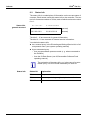
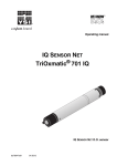
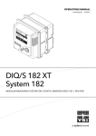
OPERATING MANUAL ba76014d03 FDO® 70x IQ FDO® 70x IQ H FDO® 70x IQ SW FDO® 70x IQ FDO® 70x IQ SW FDO® 70x IQ H OPTICAL SENSOR FOR DISSOLVED OXYGEN 05/2014 FDO® 70x IQ ... For the most recent version of the manual, please visit www.ysi.com. Contact Copyright YSI 1725 Brannum Lane Yellow Springs, OH 45387 USA Tel: +1 937-767-7241 800-765-4974 Email: [email protected] Internet: www.ysi.com © 2013 Xylem Inc. ba76014d03 05/2014 FDO® 70x IQ ... Contents FDO® 70x IQ ... - Contents 1 Overview . . . . . . . . . . . . . . . . . . . . . . . . . . . . . . . . . . . . . . . . . . . . . . . . . . . . . . . . . . . 1-1 1.1 1.2 1.3 1.4 2 Safety . . . . . . . . . . . . . . . . . . . . . . . . . . . . . . . . . . . . . . . . . . . . . . . . . . . . . . . . . . . . . . 2-1 2.1 2.2 2.3 3 Scope of delivery . . . . . . . . . . . . . . . . . . . . . . . . . . . . . . . . . . . . . . . . . . . . . . . . . . . . . . . . 3-1 Installation . . . . . . . . . . . . . . . . . . . . . . . . . . . . . . . . . . . . . . . . . . . . . . . . . . . . . . . . . . . . . 3-1 Commissioning / Getting the instrument ready for measuring . . . . . . . . . . . . . . . . . . . . . 3-3 FDO® 70x IQ ... setting table . . . . . . . . . . . . . . . . . . . . . . . . . . . . . . . . . . . . . . . . . . . . . . . 3-4 Measuring / Operation . . . . . . . . . . . . . . . . . . . . . . . . . . . . . . . . . . . . . . . . . . . . . . . . 4-1 4.1 4.2 5 Safety information . . . . . . . . . . . . . . . . . . . . . . . . . . . . . . . . . . . . . . . . . . . . . . . . . . . . . . . 2-1 2.1.1 Hazard warnings in this operating manual . . . . . . . . . . . . . . . . . . . . . . . . . . . . . . 2-1 2.1.2 Safety information on the product . . . . . . . . . . . . . . . . . . . . . . . . . . . . . . . . . . . . 2-1 Safe operation . . . . . . . . . . . . . . . . . . . . . . . . . . . . . . . . . . . . . . . . . . . . . . . . . . . . . . . . . . 2-2 2.2.1 Authorized use . . . . . . . . . . . . . . . . . . . . . . . . . . . . . . . . . . . . . . . . . . . . . . . . . . . 2-2 2.2.2 Requirements for safe operation . . . . . . . . . . . . . . . . . . . . . . . . . . . . . . . . . . . . . 2-2 2.2.3 Unauthorized use . . . . . . . . . . . . . . . . . . . . . . . . . . . . . . . . . . . . . . . . . . . . . . . . . 2-2 Hazardous location use (FDO® 70x IQ H models) . . . . . . . . . . . . . . . . . . . . . . . . . . . . . . 2-3 Commissioning . . . . . . . . . . . . . . . . . . . . . . . . . . . . . . . . . . . . . . . . . . . . . . . . . . . . . . 3-1 3.1 3.2 3.3 3.4 4 How to use this component operating manual . . . . . . . . . . . . . . . . . . . . . . . . . . . . . . . . . 1-1 Sensor models . . . . . . . . . . . . . . . . . . . . . . . . . . . . . . . . . . . . . . . . . . . . . . . . . . . . . . . . . 1-2 Recommended fields of application . . . . . . . . . . . . . . . . . . . . . . . . . . . . . . . . . . . . . . . . . 1-3 Structure . . . . . . . . . . . . . . . . . . . . . . . . . . . . . . . . . . . . . . . . . . . . . . . . . . . . . . . . . . . . . . 1-4 Measuring . . . . . . . . . . . . . . . . . . . . . . . . . . . . . . . . . . . . . . . . . . . . . . . . . . . . . . . . . . . . . 4-1 Function check and user calibration . . . . . . . . . . . . . . . . . . . . . . . . . . . . . . . . . . . . . . . . . 4-1 4.2.1 General information . . . . . . . . . . . . . . . . . . . . . . . . . . . . . . . . . . . . . . . . . . . . . . . 4-1 4.2.2 Function check . . . . . . . . . . . . . . . . . . . . . . . . . . . . . . . . . . . . . . . . . . . . . . . . . . . 4-2 4.2.3 User calibration 4-4 4.2.4 Calibration history 4-6 4.2.5 Reactivating previous calibration data 4-7 Maintenance, cleaning, replacement parts . . . . . . . . . . . . . . . . . . . . . . . . . . . . . . . 5-1 5.1 5.2 5.3 5.4 5.5 General maintenance instructions . . . . . . . . . . . . . . . . . . . . . . . . . . . . . . . . . . . . . . . . . . . 5-1 Handling of the sensor cap . . . . . . . . . . . . . . . . . . . . . . . . . . . . . . . . . . . . . . . . . . . . . . . . 5-2 Exchanging the sensor cap . . . . . . . . . . . . . . . . . . . . . . . . . . . . . . . . . . . . . . . . . . . . . . . . 5-2 Cleaning the sensor . . . . . . . . . . . . . . . . . . . . . . . . . . . . . . . . . . . . . . . . . . . . . . . . . . . . . 5-3 5.4.1 Exterior cleaning . . . . . . . . . . . . . . . . . . . . . . . . . . . . . . . . . . . . . . . . . . . . . . . . . 5-3 5.4.2 Interior cleaning of sensor cap and sensor head 5-4 Replacement parts and accessories . . . . . . . . . . . . . . . . . . . . . . . . . . . . . . . . . . . . . . . . . 5-5 6 What to do if... . . . . . . . . . . . . . . . . . . . . . . . . . . . . . . . . . . . . . . . . . . . . . . . . . . . . . . . 6-1 7 Technical data . . . . . . . . . . . . . . . . . . . . . . . . . . . . . . . . . . . . . . . . . . . . . . . . . . . . . . . 7-1 7.1 7.2 ba76014e03 General measurement characteristics . . . . . . . . . . . . . . . . . . . . . . . . . . . . . . . . . . . . . . . 7-1 Application conditions . . . . . . . . . . . . . . . . . . . . . . . . . . . . . . . . . . . . . . . . . . . . . . . . . . . . 7-1 05/2014 0-1 Contents 7.3 7.4 7.5 7.6 7.7 8 Ordering & Technical Support . . . . . . . . . . . . . . . . . . . . . . . . . . . . . . . . . . . . . . . . . . . . . .8-1 Service Information . . . . . . . . . . . . . . . . . . . . . . . . . . . . . . . . . . . . . . . . . . . . . . . . . . . . . .8-1 Indexes . . . . . . . . . . . . . . . . . . . . . . . . . . . . . . . . . . . . . . . . . . . . . . . . . . . . . . . . . . . . . 9-1 9.1 9.2 0-2 General data . . . . . . . . . . . . . . . . . . . . . . . . . . . . . . . . . . . . . . . . . . . . . . . . . . . . . . . . . . .7-2 Instrument safety . . . . . . . . . . . . . . . . . . . . . . . . . . . . . . . . . . . . . . . . . . . . . . . . . . . . . . . .7-3 7.4.1 General instrument safety . . . . . . . . . . . . . . . . . . . . . . . . . . . . . . . . . . . . . . . . . . .7-3 7.4.2 Hazardous location ratings (H models) . . . . . . . . . . . . . . . . . . . . . . . . . . . . . . . . .7-3 Electrical data . . . . . . . . . . . . . . . . . . . . . . . . . . . . . . . . . . . . . . . . . . . . . . . . . . . . . . . . . .7-3 Technical data of the SC-FDO® 700 . . . . . . . . . . . . . . . . . . . . . . . . . . . . . . . . . . . . . . . . .7-4 Technical data of the SC-FDO® 701 . . . . . . . . . . . . . . . . . . . . . . . . . . . . . . . . . . . . . . . . .7-5 Contact Information . . . . . . . . . . . . . . . . . . . . . . . . . . . . . . . . . . . . . . . . . . . . . . . . . . 8-1 8.1 8.2 9 FDO® 70x IQ ... Explanation of the messages . . . . . . . . . . . . . . . . . . . . . . . . . . . . . . . . . . . . . . . . . . . . . . .9-1 9.1.1 Error messages . . . . . . . . . . . . . . . . . . . . . . . . . . . . . . . . . . . . . . . . . . . . . . . . . .9-1 9.1.2 Info messages 9-3 Status info . . . . . . . . . . . . . . . . . . . . . . . . . . . . . . . . . . . . . . . . . . . . . . . . . . . . . . . . . . . . .9-4 ba76014e03 05/2014 FDO® 70x IQ ... Overview 1 Overview 1.1 How to use this component operating manual Structure of the IQ SENSORNET operating manual IQ Sensor Net Operating Manual System Operating Manual (Ring Binder) IQ Sensor Operating Manual MIQ Module Operating Manual MIQ Terminal Operating Manual Component Operating Manuals Fig. 1-1 Structure of the IQ SENSORNET operating manual The IQ SENSOR NET operating manual has a modular structure like the IQ SENSORNET system itself. It consists of a system operating manual and the operating manuals of all the components used. Please file this component operating manual into the ring binder of the system operating manual. ba76014e03 05/2014 1-1 FDO® 70x IQ ... Overview 1.2 Sensor models The FDO® 70x IQ ... consists of a sensor basis equipped with different sensor cap types, depending on the model: Sensor basis FDO® 700 IQ FDO® 700 IQ H Sensor cap: SC-FDO® 700 SC-FDO® 701 Sensor basis FDO® 700 IQ SW Sensor models Sensor model Sensor basis Sensor cap FDO® 700 IQ FDO® 700 IQ * SC-FDO® 700 FDO® 700 IQ SW FDO® 700 IQ SW * SC-FDO® 700 FDO® 701 IQ FDO® 700 IQ * SC-FDO® 701 FDO® 701 IQ SW FDO® 700 IQ SW * SC-FDO® 701 FDO® 700 IQ H FDO® 700 IQ H ** SC-FDO® 700 FDO® 701 IQ H FDO® 701 IQ H ** SC-FDO® 701 * Type designation on the name plate in the plug head connector ** Type designation on the name plate on the shaft The sensor cap primarily determines the measuring characteristics of the sensor as a whole. Thus the sensor can be adapted to the measuring job by exchanging the type of sensor cap. The specifications of the individual sensor cap types are given in chapter 7 TECHNICAL DATA. H models SW models 1-2 The sensor models FDO® 700 IQ H and FDO® 701 IQ H are rated for use in Class I Division 2 hazardous locations (see chapter 2.3 for details). Compared to the standard models, the sea water models of the sensors (SW models) are optimized concerning their resistance to corrosion in sea water and brackish water. ba76014e03 05/2014 FDO® 70x IQ ... Overview 1.3 Recommended fields of application Sensor model Recommended field of application. FDO® 700 IQ FDO® 701 IQ Stationary measurements in water/wastewater applications in non-hazardous locations only. FDO® 700 IQ H FDO® 701 IQ H Stationary measurements in water/wastewater applications in Class I Division 2 hazardous locations. FDO® 700 IQ SW FDO® 701 IQ SW Stationary measurements in seawater, aquaculture. The FDO® 70x IQ SW is equipped with a protective hood that is prepared for the connection of the MSK FDO® CS cleaning set for compressed air-driven sensor cleaning (order information, see section 5.5 REPLACEMENT PARTS AND ACCESSORIES). ba76014e03 05/2014 1-3 FDO® 70x IQ ... Overview 1.4 Structure 1 Structure 2 9 3 Fig. 1-2 Sensor cap with memory chip 4 5 6 7 8 Structure of the D. O. sensor (example: FDO® 70x IQ) 1 Shaft 2 Plug head connector 3 Fixing ring 4 Sensor membrane 5 Sensor cap with memory chip 6 Gold-plated contact pins for memory chip 7 Measurement window 8 Temperature sensor and locking device 9 Sensor head A memory chip is integrated in the sensor cap. The following data is stored on the memory chip: Type designation of the sensor cap Series number Data of the factory calibration Intelligent membrane (IQMC technology) 1-4 For each membrane the individual calibration values are determined by a factory calibration and stored on the memory chip of the sensor cap, ensuring maximum accuracy over the whole lifetime of the sensor. ba76014e03 05/2014 FDO® 70x IQ ... Safety 2 Safety 2.1 Safety information 2.1.1 Hazard warnings in this operating manual The hazard warnings are defined for the following levels of danger: DANGER DANGER indicates an imminently hazardous situation which, if not avoided, will result in death or serious injury. WARNING WARNING indicates a potentially hazardous situation which, if not avoided, could result in death or serious injury. CAUTION CAUTION indicates a potentially hazardous situation which, if not avoided, may result in minor or moderate injury. NOTICE NOTICE is used to address practices not related to personal injury. 2.1.2 Safety information on the product Note all labels, information signs and safety symbols on the product. ba76014e03 05/2014 2-1 FDO® 70x IQ ... Safety 2.2 Safe operation 2.2.1 Authorized use The authorized use of the FDO® 70x IQ ... comprises its use as a D.O. sensor in the IQ SENSORNET. The technical specifications according to chapter 7 TECHNICAL DATA must be observed. Only operation according to the instructions in this operating manual is authorized. Any other use is considered to be unauthorized. Unauthorized use invalidates any claims with regard to the guarantee. 2.2.2 Requirements for safe operation Note the following points for safe operation: The product may only be operated according to the authorized use specified above. The product may only be supplied with power by the energy sources specified in this operating manual. The product may only be operated under the environmental conditions specified in this operating manual. The product or its components may only be opened if this is required for installation and maintenance work and described in the operating manual. 2.2.3 Unauthorized use The product must not be put into operation if: it is visibly damaged (e.g. after being transported) it was stored under adverse conditions for a lengthy period of time (storing conditions, see chapter 7 TECHNICAL DATA) 2-2 ba76014e03 05/2014 FDO® 70x IQ ... Safety 2.3 Hazardous location use (FDO® 70x IQ H models) DANGER Explosion hazard. Only hazardous location rated sensor models ("Hazloc Sensor") must be used in hazardous locations. Read the name plate on the sensor shaft and verify that the sensor is rated for your specific application. Rated sensor models The following sensor models are rated for hazardous location use: FDO® 700 IQ H (YSI-Order No. 207065Y) FDO® 701 IQ H (YSI-Order No. 207066Y) Hazardous location rated sensors are identified by the name plate with the rating details engraved on the sensor shaft: Name plate of a Hazloc sensor (example) FDO 700 IQ H ###### ###### ###### 28123 ######### ############### #################### ################# DANGER Explosion hazard. The associated apparatus MIQ/BB1 (YSI part no. 207001Y) has to be used for connection. Refer to the following documents for proper installation: Control drawing, YSI document no. 28123 (see MIQ/BB1 operating manual) MIQ/BB1 operating manual All applicable electrical code regulations. DANGER Explosion hazard. This product does not meet the requirements of the directive 94/9/EC (ATEX). ba76014e03 05/2014 2-3 Safety 2-4 FDO® 70x IQ ... ba76014e03 05/2014 FDO® 70x IQ ... Commissioning 3 Commissioning 3.1 Scope of delivery Sensor, consisting of sensor basis and sensor cap Operating manual. 3.2 Safety guidelines for installation in a hazardous location (H-models only) Connection cable Installation DANGER Explosion hazard. Only hazardous location rated sensor models ("Hazloc Sensor") must be used in hazardous locations. Verify the rating on the product name plate on the sensor shaft. The associated apparatus MIQ/BB1 (YSI part no. 207001Y) has to be used for connection. Refer to the following documents for proper installation: Control drawing, YSI document no. 28123 (see MIQ/BB1 operating manual) MIQ/BB1 operating manual All applicable electrical code regulations. A sensor connection cable of the SACIQ or SACIQ SW type is required to connect the sensor. The cable is available in different lengths. Compared to the standard model SACIQ, the SACIQ SW sensor connection cable is optimized regarding its corrosion resistance in seawater and brackish water and adapted for use in conjunction with the FDO 70x IQ SW. Information on this and other IQ SENSORNET accessories is given in the YSI catalog and on the Internet. DANGER Explosion hazard. For hazardous location use only the cable types listed in the control drawing must be used. How to connect the SACIQ (SW) sensor connection cable to the terminal strip of a MIQ module is described in chapter 3 INSTALLATION of the IQ SENSORNET system operating manual. ba76014e03 05/2014 3-1 FDO® 70x IQ ... Commissioning Are the plug connections dry? Before connecting the sensor and sensor connection cable, please make sure the plug connections are dry. If moisture gets into the plug connections, first dry the plug connections (dab them dry or blow them dry using compressed air). Do not suspend the sensor on the sensor connection cable. Use a sensor holder or armature. Information on this and other IQ SENSORNET accessories is given in the YSI catalog and on the Internet. Connecting the sensor to the sensor connection cable 1 Take the protective caps off the plug connections of the sensor and the SACIQ (SW) sensor connection cable and keep them safe. 2 Plug the jack of the SACIQ (SW) sensor connection cable onto the plug head connector of the sensor. At the same time, rotate the socket so that the pin in the plug head connector (1) clicks into one of the two holes in the socket. 3 Then screw the coupling ring (2) of the sensor connection cable onto the sensor up to the stop. SACIQ 2 1 Fig. 3-1 3-2 Connecting the sensor ba76014e03 05/2014 FDO® 70x IQ ... Commissioning 3.3 Identification in the IQ SENSORNET Commissioning steps ba76014e03 05/2014 Commissioning / Getting the instrument ready for measuring Both the sensor cap and sensor basis (sensor without cap) have a series number of their own. The sensor has to be equipped with a sensor cap for a successful login to the IQ SENSORNET. The operable sensor is displayed as follows in the list of sensors: Model: Model designation of the sensor cap (="SC FDO 70x") Ser. no.: Series number of the sensor cap Sensor name: The series number of the sensor basis is preset here. You can change this entry as necessary by entering a user-defined name. 1 Pull the protective cap off the sensor. 2 If required, assign a user-defined name to the sensor (see relevant IQ SENSORNET system operating manual). 3 When using IQ SENSORNET without automatic air pressure compensation the mean air pressure value or the location altitude has to be entered (for more detailed information see the relevant IQ SENSORNET system operating manual). 4 Set the sensor (see section 3.4). 3-3 FDO® 70x IQ ... Commissioning 3.4 FDO® 70x IQ ... setting table Setting Selection/values Explanation Measuring mode Concentration Unit of the measured value on the measured value display. Saturation Measuring range Concentration 0 ... 20.00 mg/l 0 ... 20.00 ppm These measuring ranges are available for selection. Measuring range Saturation 0 ... 200.0 % The measuring range is set permanently. Response time t90 150 .. 300 s Response time of the signal filter. Depending on the sample matrix, the measured values may fluctuate more or less. A signal filter in the sensor reduces the fluctuation range of the measured value. The signal filter is characterized by the Response time t90. This is the time after which 90 % of a signal change is displayed. (with SC-FDO® 700) or 60 ... 300 s (with SC-FDO® 701) The setting range depends on the sensor cap type. Calibration Factory calibration User calibration active abort Determines which calibration data the measured value calculation will be based on. The active calibration is displayed in the calibration history. The selection, User calibration is only displayed if valid data of a User calibration is stored in the sensor. active indicates that the sensor is being calibrated. If abort is selected, the active calibration is canceled the next time the setting table is quit with Save and quit. Test active abort active indicates that the sensor is being checked. If abort is selected, the active check is canceled the next time the setting table is quit with Save and quit. Temperature mode °C °F 3-4 Unit of the measured temperature value (Celsius, Fahrenheit). ba76014e03 05/2014 FDO® 70x IQ ... Commissioning Setting Selection/values Explanation Temp. adjustment -1.5 K ... +1.5 K The temperature compensation enables the temperature display to be balanced (shifting of the zero point by ±1.5K). Notes: Due to the thermal capacity of the sensor, it is necessary to place it in a container with at least 2 liters of water. Leave the sensor in this container for at least 15 minutes while stirring occasionally until the balancing can be performed. With temperature differences between the water and sensor > 10 °C, leave the sensor for at least 1 hour in this container while stirring occasionally until the balancing can be performed. Salinity On Off Determines whether the entered salinity should be taken into account. Salinity input 2.0 ... 70.0 The entry of the salinity enables a salt content correction that compensates for the effect of salt contents > 0.1 % on the oxygen measurement. The salt content correction is recommended for measurements in salt-contaminated wastewater (salinity ≥ 2.0 corresponding to a conductivity of ≥ 3.4 mS/cm at a reference temperature TREF = 20 °C). Sensor cap data Do not download Generates a log book message with all data stored in the sensor cap when the settings are quit with Save and quit (see section 1.2). When opening the menu again the setting is reset to Do not download. Transmit to log book Save and quit The system confirms the saving of the settings and the display switches to the next higher level. Quit The display switches to the next higher level without saving the new settings. Carrying out settings ba76014e03 05/2014 Using <S>, switch from the measured value display to the main menu of the settings. Then navigate to the setting menu (setting table) of the sensor. The exact procedure is given in the relevant IQ SENSORNET system operating manual. 3-5 Commissioning 3-6 FDO® 70x IQ ... ba76014e03 05/2014 FDO® 70x IQ ... Measuring / Operation 4 Measuring / Operation 4.1 Measuring WARNING Chemical or biological hazard. Contact with the sample can be harmful to the user. Depending on the type of sample, suitable protective measures must be taken (protective clothing, goggles, etc.). Note the data given in section 7.2 APPLICATION CONDITIONS, especially the minimum immersion depth of the sensor (> 50 mm). The measured value is available immediately on submersing. If keeping the sensor clean is a problem, we recommend using the compressed air-driven cleaning system with the CH cleaning head (see section 5.5 REPLACEMENT PARTS AND ACCESSORIES). 4.2 Function check and user calibration 4.2.1 General information Factory calibration The FDO® 70x IQ ... is factory calibrated. In the recommended application (see section 1.3 RECOMMENDED FIELDS OF APPLICATION), the measuring characteristics of the sensor cap remain stable for the specified service life. Thus, a user calibration is not usually required. When does a function check or user calibration make sense? A function check or user calibration can be useful in the following special cases: If the measured values appear to be implausible and it is assumed that the service life of the sensor cap is over Routinely within the framework of the company quality assurance. Check or calibration medium Select one of the following two variants depending on the air temperature at the calibration site: With air temperatures over 5 °C, the function check and user calibration ideally take place in water vapor-saturated air. To do so, position the sensor approx. 2 cm above a water surface, for example in a narrow bucket or similar container with water. The membrane must be clean and dry for this. ba76014e03 05/2014 4-1 FDO® 70x IQ ... Measuring / Operation 2 cm With air temperatures under 5 °C we recommend performing the function check and user calibration not in air but in air-saturated water that has a higher temperature. You obtain air-saturated water by pouring water several times in and out of two vessels so that it sparkles. 4.2.2 Function check A function check is the simplest way to determine whether the sensor needs to be cleaned or user-calibrated. Principle Steps 4-2 The function check can either be done in water vapor-saturated air or in air-saturated water (see CHECK OR CALIBRATION MEDIUM on page 4-1). Generally, a check on the IQ SENSORNET is carried out as follows. System specific details are given in the respective IQ SENSORNET system operating manual. 1 Switch to the measured value display with <M> and select the FDO® 70x IQ ... sensor. 2 Press <C>. The next step switches on the maintenance condition for the sensor. A corresponding message appears on the display. 3 Confirm the note with <OK>. The maintenance condition is active. 4 Select the TEST procedure and press <OK>. 5 Put the sensor into the calibration position (water vapor-saturated air or air-saturated water - see section 4.2.1). 6 Press <OK>. The sensor starts the check. The display switches to the measured value display. The CAL indicator flashes instead of the main measured value. At the same time, the momentary relative slope flashes as the secondary measured value with the addition of TEST. The process ends automatically as soon as the measured values meet the criterion for the stability control. With a great temperature difference between the sensor and the environment this may take a while. Subsequently, the main measured value and temperature are displayed. ba76014e03 05/2014 FDO® 70x IQ ... Canceling the check Measuring / Operation 7 Put the sensor in the measuring position again. 8 Wait for the measured value to be largely stable (temperature adjustment). 9 Switch off the maintenance condition. As long as the determination of the relative slope has not yet been started (step 6), you can quit the check with <M> or <ESC>. The running determination of the relative slope (after pressing <OK> in step 6) can be aborted as follows: Evaluation 1 Open the setting table (see section 3.4). 2 In the Test menu item, select the abort setting and then quit the setting table with Save and quit. The result of the check is entered in the log book of the sensor. If the relative slope is outside the tolerance range (0.90 ... 1.10), the check is assessed as erroneous. The information recorded in the log book entry is partly identical with that of the calibration history. The calibration history is described in detail in section 4.2.4 CALIBRATION HISTORY. ba76014e03 05/2014 4-3 FDO® 70x IQ ... Measuring / Operation 4.2.3 Principle User calibration The user calibration can either be done in water vapor-saturated air or in air-saturated water (see CHECK OR CALIBRATION MEDIUM on page 4-1). With the calibration procedure, the relative slope of the sensor is determined. The calibration is evaluated based on the relative slope and the intensity (successful <-> unsuccessful). The result of the user calibration is stored in the calibration record and calibration history respectively and can be viewed afterwards (see respective IQ SENSORNET system operating manual). We want to point out that the factory calibration of the membrane is highly precise due to the IQMC technology. If you still want to carry out a user calibration, influences due to environmental conditions have to be taken into account. Steps 4-4 Generally, a user calibration on the IQ SENSORNET is carried out as follows. System specific details are given in the respective IQ SENSORNET system operating manual. 1 Switch to the measured value display with <M> and select the FDO® 70x IQ ... sensor. 2 Press <C>. The next step switches on the maintenance condition for the sensor. A corresponding message appears on the display. 3 Confirm the note with <OK>. The maintenance condition is active. 4 Select the CALIBRATION procedure and press <OK>. 5 Put the sensor into the calibration position (water vapor-saturated air or air-saturated water - see section 4.2.1). 6 Press <OK>. The sensor determines the calibration data. The display switches to the measured value display. The CAL indicator flashes instead of the main measured value. At the same time, the momentary relative slope flashes as the secondary measured value. The process ends automatically as soon as the measured values meet the criterion for the stability control. With a great temperature difference between the sensor and the environment this may take a while. Subsequently, the main measured value and temperature are displayed. 7 If the user calibration was successful, bring the sensor into the measuring position again. 8 Wait for the measured value to be largely stable (temperature adjustment). 9 Switch off the maintenance condition. ba76014e03 05/2014 FDO® 70x IQ ... Canceling the user calibration Measuring / Operation As long as the determination of the calibration data has not yet been started (step 6), you can quit the calibration routine with <M> or <ESC>. The running determination of calibration data (after pressing <OK> in step 6) can be aborted as follows: 1 Open the setting table (see section 3.4). 2 In the Calibration menu item, select the abort setting and then quit the setting table with Save and quit. After the user calibration was canceled the sensor again works with the calibration data that was used before the canceled user calibration. Possible results of the user calibration ba76014e03 05/2014 The calibration data is evaluated by the system. A calibration can have the following results: Display Explanation Measured value display Sensor was successfully calibrated. The calibration data can be viewed in the calibration history (section 4.2.4). "----" The sensor could not be calibrated. The sensor is blocked for further measurement. Notes on possible causes are given in the log book of the sensor. 4-5 FDO® 70x IQ ... Measuring / Operation 4.2.4 Calibration history Calibration history (available in the IQ SENSORNET systems 184 XT and 2020 XT only) Currently active calibration Chronological list of the last user calibrations Fig. 4-1 Calibration historyFDO® 70x IQ ... The calibration history contains the following information: Date Calibration date (Factory = factory calibration) Rel.slope Relative slope (non-dimensional) Intens. Intensity: + - Res : : sufficient too low Evaluation of the calibration o.k. : Calibration successful. The new calibration data was taken over for measurement. Error : Calibration unsuccessful. Invalid calibration data were discarded. Measurement was continued with the last valid values. The calibration history is stored in the sensor basis. If another sensor cap (with different series number) is mounted, the calibration history is deleted and cannot be restored afterwards. 4-6 ba76014e03 05/2014 FDO® 70x IQ ... Measuring / Operation 4.2.5 Reactivating previous calibration data The FDO® 70x IQ ... enables you to reactivate the last valid user calibration or the factory calibration. Thus you can immediately go on measuring if a calibration procedure failed or you suspect that the calibration conditions were not optimally met. Reactivating old calibration data is only a temporary solution. Please take into account that the sensor might thus possibly provide incorrect measured values. Please make sure the sensor works correctly by carrying out a function check and/or recalibration. Reactivating calibration data ba76014e03 05/2014 1 Open the setting table (see section 3.4). 2 In the Calibration menu item, select the User calibration or Factory calibration setting and then quit the setting table with Save and quit. 4-7 Measuring / Operation 4-8 FDO® 70x IQ ... ba76014e03 05/2014 FDO® 70x IQ ... Maintenance, cleaning, replacement parts 5 Maintenance, cleaning, replacement parts 5.1 General maintenance instructions WARNING Chemical or biological hazard. Contact with the sample can be harmful to the user. Depending on the type of sample, suitable protective measures must be taken (protective clothing, goggles, etc.). Maintenance condition We recommend to switch on the maintenance condition each time the sensor is taken out of the measuring position. This avoids unwanted reactions of linked outputs. For more detailed information on the maintenance condition please refer to the respective IQ SENSORNET system operating manual. We do not recommend unscrewing the sensor from the sensor connection cable in order to do maintenance work. Otherwise, moisture and/or dirt can get into the plug connection where it can cause contact problems. If you would like to disconnect the sensor from the sensor connection cable, please note the following points: Before disconnecting the sensor from the SACIQ (SW) sensor connection cable, the sensor has to be cleaned on the outside (see section 5.4.1). Unscrew the sensor from the SACIQ (SW) sensor connection cable. Place a protective cap on the sensor plug head connector and on the SACIQ (SW) sensor connection cable each time so that no moisture or dirt can get on the contacting surfaces. In corrosive environments, close the socket of the sensor connection cable with the screwable SACIQ-Plug when it is dry in order to protect the electrical contacts from corrosion. The protective plug is available as an accessory (see section 5.5 REPLACEMENT PARTS AND ACCESSORIES). It is included in the standard scope of delivery of the SACIQ SW sensor connection cable. ba76014e03 05/2014 5-1 FDO® 70x IQ ... Maintenance, cleaning, replacement parts 5.2 Handling of the sensor cap Despite its exterior robustness, the sensor is an optical high precision instrument. Therefore, special care should be taken when doing any maintenance or cleaning work: Dirt and moisture under the sensor cap can affect the functioning and shorten the service life of the sensor cap. Therefore, make sure the working environment is clean and dry prior to removing the sensor cap. Please do not touch the outer sensor membrane with your fingers. Touch the sensor cap at the sides only (shaded area in figure on the left). Avoid any great mechanical stress of the sensor membrane (pressure, scratches). Exposure to light, particularly daylight of the interior of the sensor cap will, by-and-by, affect the measurement characteristics and shorten the service life of the sensor cap. Therefore, the interior of the sensor cap should not be exposed to direct sunlight. Avoid any exposure to light that exceeds the extent required for necessary maintenance and cleaning activities. Store dismantled sensor caps in a light-protected environment only. 5.3 Removing the sensor cap Exchanging the sensor cap 1 Pull the sensor out of the sample. 2 Clean the outside of the sensor (see section 5.4.1). 3 Unscrew the fixing ring from the sensor by hand. 4 Thoroughly clean and dry the sensor head once again. 5 Grasp the sensor cap on the sides (arrows in figure on the left) and remove it by pulling it away from the sensor in a straight upward direction. NOTICE Do not push any tools or other sharp objects between the sealing surfaces. This might damage the sealing surfaces. 5-2 ba76014e03 05/2014 FDO® 70x IQ ... Mounting the sensor cap Maintenance, cleaning, replacement parts 6 Check the front surface of the sensor for absolute cleanness and clean it if necessary (see section 5.4.1). 7 Thoroughly clean the thread of the fixing ring. 8 Place the new sensor cap on the sensor so that the temperature sensor fits into the hole inside the sensor cap (see figure opposite). 9 Put the fixing ring on the sensor head and screw it tight by hand. 5.4 Cleaning the sensor 5.4.1 Exterior cleaning Dirt on the sensor can affect the measuring characteristics. Biological deposits for example, consume oxygen and can, when occurring on the sensor cap membrane, impair the responding behavior and cause values that are too low. Therefore, we recommend regular visual inspections and exterior cleaning as necessary. Pay attention to the following points for cleaning: First, thoroughly rinse the sensor with tapwater to remove loosely adhering dirt. Rough dirt on the sensor shaft can be brushed off with a soft brush. Attention: Do not use the brush in the area of the sensor membrane. Risk of damage! The sensor cap including the sensor membrane should be wiped with a soft and moist microfiber cloth. In the case of persisting dirt you can add some household washingup liquid to the tapwater. Attention: Never use any alcohol for cleaning! If the are any salt or lime deposits, the sensor can be cleaned with aqueous citric acid solution (10 % weight percent). ba76014e03 05/2014 5-3 FDO® 70x IQ ... Maintenance, cleaning, replacement parts 5.4.2 Interior cleaning of sensor cap and sensor head If moisture or dirt have penetrated under the sensor cap, e.g. because the sensor cap is damaged, you can make the sensor ready for operation again as follows: NOTICE Only use nonabrasive, alcohol-free detergents, as otherwise the optical surfaces could be damaged. 1 Remove the sensor cap (see section 5.3). 2 Clean the sensor head and sensor cap: – Rinse all inner surfaces with tapwater – Remove contamination containing fat and oil with warm water and household washing-up liquid 3 Dry all surfaces with a clean, lint free cloth. A lint-free cloth such as a microfiber cloth used to clean eyeglasses is suitable. 4 Allow the sensor and sensor cap to dry completely at a dry location so moisture can evaporate even from corners difficult to access. When doing, so protect the inside of the sensor cap from light. If the sensor cap is visibly damaged it has to be replaced. 5-4 ba76014e03 05/2014 FDO® 70x IQ ... Maintenance, cleaning, replacement parts 5.5 Replacement parts and accessories Description Model Sensor cap SC-FDO® 700 201 654Y Sensor cap SC-FDO® 701 201 655Y Protective screw cap for sensor connection cable SACIQ-Plug 480 065Y MSK FDO® Protective hood against damage caused by fish, with connection for the MSK FDO® CS cleaning set Cleaning set for connection of the protective hood MSK FDO® to a valve module or Cleaning Air Box Components for compressed air cleaning system Order no. Description MSK FDO® CS Model 205 253Y 205 254Y Order no. Cleaning head CH 900 107Y Active valve module (does not require a free relay output in the IQ SENSORNET system) MIQ/CHV PLUS 480 018Y Valve module for the IQ SENSORNET system 182 (external relay and compressed air supply) DIQ/CHV 472 007Y Air compressor to be triggered by relay, power supply 115 V AC Cleaning Air Box - 115 VAC 480 017Y Air compressor to be triggered by relay, power supply 230 V AC Cleaning Air Box - 230 VAC 480 019Y Information on further IQ SENSORNET accessories is given in the YSI catalog and on the Internet. ba76014e03 05/2014 5-5 Maintenance, cleaning, replacement parts 5-6 FDO® 70x IQ ... ba76014e03 05/2014 FDO® 70x IQ ... What to do if... 6 What to do if... Sensor does not appear in the measured value display and list of sensors Cause Remedy – Sensor cap not mounted or defective – Sensor cap (see section 5.3) Measured value implausible Cause Remedy – Coating on sensor cap – Clean the outside of the sensor (see section 5.4.1) – Service life of the sensor cap over – Check the sensor (see section 4.2.2) – Replace a defective sensor cap as necessary – Replace the sensor cap as necessary (see section 5.3) – Dirt inside the sensor cap and sensor head. – Fixing ring not properly tightened. – Sensor cap untight or defective. – Dismantle sensor cap – Clean the insides of the sensor cap and sensor head (see section 5.4.2) – Mount the sensor cap correctly and tighten the fixing ring as far as it will go (see section 5.3) – Replace a defective sensor cap as necessary Measured value fluctuating heavily Cause Remedy – Coating on sensor cap – Clean the outside of the sensor (see section 5.4.1) – Service life of the sensor cap over – See point "Measured value implausible" – Dirt inside the sensor cap and sensor head. – See point "Measured value implausible" – Fixing ring not properly tightened. – Sensor cap untight or defective. ba76014e03 05/2014 6-1 FDO® 70x IQ ... What to do if... Measured value invalid ( "----" displayed) Cause Remedy – User calibration unsuccessful. The sensor is blocked for measurement. – As a temporary measure to quickly restore the readiness for service: Activate the factory calibration (see section 4.2.5) – For exact measurements, carry out a function check and repeat the user calibration if necessary. Incorrect temperature display 6-2 Cause Remedy – Temperature sensor defective – Return the sensor ba76014e03 05/2014 FDO® 70x IQ ... Technical data 7 Technical data 7.1 General measurement characteristics The measurement characteristics are primarily determined by the sensor cap type. The relevant data are given in the sections 7.6 and 7.7. Measuring principle Measurement in water Measurement in saltcontaminated wastewater Temperature measurement Temperature compensation Optical measurement based on photoluminescence. According to solubility function according to ISO 5814 Salinity input from 2.0 ... 70.0; corresponds to 3.4 mS/cm ... 86.2 mS/cm at TREF 20 °C (salinity measurement according to IOT = International Oceanographic Tables) Temperature sensor Integrated NTC Measuring range - 5 °C ... + 50 °C (23 ... 122 °F) Accuracy ± 0.5 K Resolution 0.1 K In the range -5 °C ... + 50 °C (23 ... 122 °F) 7.2 Pressure resistance Application conditions Sensor with connected SACIQ (SW) sensor connection cable: Max. allowed overpressure 106 Pa (10 bar) The sensor meets all requirements according to article 3(3) of 97/23/ EC ("pressure equipment directive"). Type of protection Sensor with connected SACIQ (SW) sensor connection cable: IP 68, 10 bar (106 Pa) Immersion depth Operating position ba76014e03 05/2014 Min. 10 cm; max. 100 m depth Any 7-1 FDO® 70x IQ ... Technical data 7.3 Dimensions General data FDO 70x IQ (H): 400 40.0 39.7 Socket SACIQ... FDO 70x IQ SW: 400 34 276 39.7 Weight (without sensor connection cable) Connection technique Material Socket SACIQ... 59.5 FDO® 70x IQ (H) Approx. 900 g FDO® 70x IQ SW Approx. 1500 g Connection via SACIQ (SW) sensor connection cable Shaft: – FDO® 70x IQ ® – FDO 70x IQ SW V4A stainless steel 1.4571 * POM Plug head connector housing POM Sensor head POM and PVC Sensor cap See section 7.6 or section 7.7 Plug, 3-pole ETFE (blue) Tefzel® Fixing ring POM Protective hood (FDO® 70x IQ SW) POM * Stainless steel can be corrodible if there are chloride concentrations of 500 mg/L or more. For applications in such media we recommend to use the SW sensors. Automatic sensor monitoring (SensCheck function) 7-2 Monitoring of the membrane function ba76014e03 05/2014 FDO® 70x IQ ... Technical data 7.4 Instrument safety 7.4.1 General instrument safety Applicable norms – UL 61010-1 – CAN/CSA C22.2 # 61010.1 7.4.2 Hazardous location ratings (H models) Applicable directives and standards In addition to the standards listed in chapter 7.4.1, the FDO® 70x IQ H conforms to the following directives and standards: ANSI/ISA-12.12.01 CAN/CSA C22.2 # 213 The FDO® 70x IQ H is a non-incendive electrical equipment for use in Class I Division 2 hazardous locations. Hazardous location rating FDO® 700 IQ H FDO® 701 IQ H Class I Division 2 Groups A, B, C, D T6 Class I Zone 2 Group IIC T6 Associated apparatus MIQ/BB1, YSI part no. 207001Y Control Drawing YSI document no. 28123 7.5 ba76014e03 05/2014 Electrical data Rated voltage (non-H models) 24 V DC via the IQ SENSORNET (for more details, see chapter TECHNICAL DATA of the IQ SENSORNET system operating manual) Voltage range (H models) 14 V DC ... 24 V DC via the MIQ/ BB1 barrier box (=associated apparatus) Power consumption 0.7 W Protective class III 7-3 FDO® 70x IQ ... Technical data 7.6 Measuring ranges and resolutions Measurement accuracy Repeatability Response time Minimum approach flow Interferences Allowed temperature range Allowed pH range of the test sample Calibration procedure Material Working life 7-4 Technical data of the SC-FDO® 700 D. O. partial pressure 0 ... 400 hPa Measuring mode Adjustable measuring range Resolution D. O. concentration 0 ... 20.00 mg/L 0 ... 20.00 ppm 0.01 mg/L 0.01 ppm D. O. saturation 0 ... 200.0 % 0.1 % In the range Accuracy < 1 mg/L (ppm) ± 0.05 mg/L (ppm) > 1 mg/L (ppm) ± 0.1 mg/L (ppm) ± 0.05 mg/L (ppm) according to EN ISO 15839 t90 (90 % of the final display value after) < 150 s according to EN ISO 15839 t95 (95 % of the final display value after) < 200 s according to EN ISO 15839 No incident flow required Non-sensitive to against hydrogen sulfide, chlorine, and ionogenic substances Measuring medium - 5 °C ... + 50 °C (23 ... 122 °F) Storage/transport - 10 °C ... + 50 °C (14 ... 122 °F) 4 ... 12 Factory calibration by means of IQMC (Intelligent Membrane Calibration) procedure. User calibration possible in water vapor-saturated air or air-saturated water. PMMA, PVC and silicone 2 years guaranteed with authorized use ba76014e03 05/2014 FDO® 70x IQ ... Technical data 7.7 Measuring ranges and resolutions Measurement accuracy Repeatability Response time Minimum approach flow Interferences Allowed temperature range Allowed pH range of the test sample Calibration procedure Material Working life ba76014e03 05/2014 Technical data of the SC-FDO® 701 D. O. partial pressure 0 ... 400 hPa Measuring mode Adjustable measuring range Resolution D. O. concentration 0 ... 20.00 mg/L 0 ... 20.00 ppm 0.01 mg/L 0.01 ppm D. O. saturation 0 ... 200.0 % 0.1 % In the range Accuracy < 1 mg/L (ppm) ± 0.05 mg/L (ppm) > 1 mg/L (ppm) ± 0.1 mg/L (ppm) ± 0.05 mg/L (ppm) according to EN ISO 15839 t90 (90 % of the final display value after) < 60 s according to EN ISO 15839 t95 (95 % of the final display value after) < 80 s according to EN ISO 15839 No incident flow required Non-sensitive to against hydrogen sulfide, chlorine, and ionogenic substances Measuring medium -5 °C ... + 40 °C (23 ... 104 °F) Storage/transport - 10 °C ... + 40 °C (-33 ... 104 °F) 4 ... 12 Factory calibration by means of IQMC (Intelligent Membrane Calibration) procedure. User calibration possible in water vapor-saturated air or air-saturated water. PMMA, PVC and silicone 6 months guaranteed for authorized use under the specified environmental conditions 7-5 Technical data 7-6 FDO® 70x IQ ... ba76014e03 05/2014 FDO® 70x IQ ... Contact Information 8 Contact Information 8.1 Ordering & Technical Support Telephone: (800) 897-4151 (937) 767-7241 Monday through Friday, 8:00 AM to 5:00 PM ET Fax: (937) 767-1058 Email: [email protected] Mail: YSI Incorporated 1725 Brannum Lane Yellow Springs, OH 45387 USA Internet: www.ysi.com When placing an order please have the following information available: YSI account number (if available) Model number or brief description Quantity 8.2 Name and Phone Number Billing and shipping address Purchase Order or Credit Card Service Information YSI has authorized service centers throughout the United States and Internationally. For the nearest service center information, please visit www.ysi.com and click ‘Support’ or contact YSI Technical Support directly at 800-897-4151. When returning a product for service, include the Product Return form with cleaning certification. The form must be completely filled out for an YSI Service Center to accept the instrument for service. The Product Return form may be downloaded at www.ysi.com and clicking on the ‘Support‘ tab. ba76014e03 05/2014 8-1 Contact Information 8-2 FDO® 70x IQ ... ba76014e03 05/2014 FDO® 70x IQ ... Indexes 9 Indexes 9.1 Explanation of the messages This chapter contains a list of all the message codes and related message texts that can occur in the log book of the IQ SENSORNET system for the FDO® 70x IQ ... sensor. Information on the contents and structure of the log book, and how to call it up, is given in the LOG BOOK chapter of the IQ SENSORNET system operating manual. The last three digits of the message code identify the source of the message: 334 = SC FDO 700 (sensor cap SC-FDO® 700) 335 = SC FDO 701 (sensor cap SC-FDO® 701) 531 = FDO700IQ (sensor basis / component class, adapter ADA) 9.1.1 Error messages Message code Message text EA133x Meas. range exceeded or undercut * Check process * Select other meas. range EA233x Sensor temperature too high! * Check process and application EA333x Sensor temperature too low! * Check process and application EAP33x Measurement interfered * SensCheck: Sensor cap is missing, leaky, depleted, or defective * Clean sensor and space between cap and sensor according to op.instructions * Screw on sensor cap securely * Replace sensor cap EAP531 Measurement interfered * SensCheck: Sensor cap is missing, leaky, depleted, or defective * Clean sensor and space between cap and sensor according to op.instructions * Screw on sensor cap securely * Replace sensor cap ba76014e03 05/2014 9-1 FDO® 70x IQ ... Indexes Message code Message text EC833x Sensor could not be calibrated, sensor blocked for measurement Cause: instable signal * Check temperature adjustment * Check calibration conditions (see operating manual) * Repeat calibration EC933x Calibration error, measurement disabled Cause: Sensor cap is missing, leaky, depleted, or defective * Clean sensor and space between cap and sensor according to op.instructions * Screw on sensor cap securely * Repeat calibration * Replace sensor cap EI133x Operational voltage too low * Check installation and cable lengths, Follow installation instructions * Power supply module(s) overloaded, add power supply module(s) * Check terminal and module connections * Defective components, replace components EI233x Operational voltage too low, no operation possible * Check installation and cable lengths, Follow installation instructions * Power supply module(s) overloaded, add power supply module(s) * Check terminal and module connections * Defective components, replace components ES133x Component hardware defective * Contact service 9-2 ba76014e03 05/2014 FDO® 70x IQ ... Indexes 9.1.2 Info messages Message code Message text IC133x Sensor has been successfully calibrated * For calibration data, see calibration history IC333x Factory calibration has been activated. Make sure the sensor operates correctly. IC433x Last valid calibration has been activated. Make sure the sensor operates correctly. IC533x Invalid user calibration has been replaced by last valid user calibration. Caution! Wrong measured values possible. Carry out a new successful calibration to make sure the sensor operates correctly.es correctly. IC633x The invalid user calibration was replaced by the factory calibration. Caution! Wrong measured values possible. Check whether the sensor operates correctly or carry out a new successful calibration.user calibration. IC733x This message displays the result of the last check (see section 4.2.2) IS133x This message displays the information stored in the sensor cap (see section 1.2) ba76014e03 05/2014 9-3 FDO® 70x IQ ... Indexes 9.2 Status info The status info is a coded piece of information on the current status of a sensor. Each sensor sends this status info to the controller. The status info of sensors consists of 32 bits, each of which can have the value 0 or 1. Status info, general structure 0 1 2 3 4 5 6 7 8 9 10 11 12 13 14 15 10000000 00000000 (general) 00000000 00000000 (internal) 16 17 18 19 20 21 22 23 24 25 26 27 28 29 30 31 The bits 0 - 15 are reserved for general information. The bits 16 - 21 are reserved for internal service information. You obtain the status info: via a manual query in the Einstellungen/Settings/Service/List of all components menu (see system operating manual) by an automated query – from a superordinate process control (e. g. when connected to the Profibus) – from the IQ Data Server (see IQ SENSORNET Software Pack operating manual) The evaluation of the status info, e.g. in the case of an automated query, has to be made individually for each bit. Status info 9-4 Status bit Explanation Bit 0 Component hardware defective Bit 1 Sensor cap missing, untight, depleted or defective Bit 2-31 - ba76014e03 05/2014 Xylem |'zīləm| 1) The tissue in plants that brings water upward from the roots; 2) a leading global water technology company. We're 12,500 people unified in a common purpose: creating innovative solutions to meet our world's water needs. Developing new technologies that will improve the way water is used, conserved, and re-used in the future is central to our work. We move, treat, analyze, and return water to the environment, and we help people use water efficiently, in their homes, buildings, factories and farms. In more than 150 countries, we have strong, long-standing relationships with customers who know us for our powerful combination of leading product brands and applications expertise, backed by a legacy of innovation. For more information on how Xylem can help you, go to www.xyleminc.com YSI 1725 Brannum Lane Yellow Springs, OH 45387 Tel: +1 937-767-7241; 800-765-4974 Fax: +1 937-767-1058 Email: [email protected] Web: www.ysi.com ©Xylem Inc