1
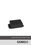
ELAN3-ALARM ETHERNET COMMUNICATOR User Manual v1.1 Compatibility: • ELAN3-ALARM v0.3 and up + ESIM364 v02.07.00 and up. • ELAN3-ALARM v0.4 and up + ET082 v01.12.00 and up; hardware version: ET082-30 and up. Main features: • Supported Ethernet connectivity: 10/100 Mbit. • Enables Internet access on ESIM364/ET082 via Ethernet interface. • Automated configuration. ELAN3-ALARM is an add-on device designed to use with ESIM364 alarm system or ET082 communicator and operate in IP-based networks. The device is an Ethernet-based communicator that enables instant Internet access allowing to perform the following: • Establish a communication between ESIM364/ET082 and EGR100 middleware, Kronos or SIA IP protocol-based monitoring station software. • Connect ESIM364 to ELDES Smart Security platform. • Configure ESIM364/ET082 remotely. 1.CONTENTS OF PACK Item.................................................... Quantity 1. ELAN3-ALARM......................................... 1 2. User manual............................................. 1 Not included: · NSG 25-3 cable - can be obtained from your local supplier. 2.TECHNICAL SPECIFICATIONS 2.1. Electrical & Mechanical Characteristics Power supply������������������������������������������������������������������������������������������10-24V 50Hz ~ 210mA max. / 10-24V 210mA max. Dimensions���������������������������������������������������������������������������������������������70x85x57 mm Operating temperature range �������������������������������������������������������������-20…+55 °C Humidity �������������������������������������������������������������������������������������������������0-90% RH @ 0... +40 °C (non-condensing) 2.2. Main Unit, LED Indicator & Connector Functionality FRONT SIDE RJ45 1 SIDE VIEW USB LAN (green) USB RS232 DEF STATUS CONNECT F1 AC/DC 2 G EN Y LAN (yellow) RJ45 RS232 RS232 interface for communication with ET082 RJ45 10/100Base-T Ethernet port USB Mini USB port for firmware update DEF Pins for fimware update STATUS Red light-emitting diode indicating micro-controller status CONNECT Green light-emitting diode indicating RS485/RS232 connectivity status F1 miniSMDC 0,5A fuse AC/DC Power supply terminals G RS485 interface for communication with ESIM364 (green wire) Y RS485 interface for communication with ESIM364 (yellow wire) LAN (green) Green light-emitting diode indicating Ethernet activity LAN (yellow) Yellow light-emitting diode indicating Ethernet status ELAN3-ALARM Ethernet Communicator 3.INSTALLATION ATTENTON: The wiring is permitted to be done only while ESIM364 system is completely powered down. 1. ESIM364: Connect ELAN3-ALARM device’s AC/DC terminals to ESIM364 system’s AUX+ and AUX- terminals (see Fig. No. 2). ET082: Connect ELAN3-ALARM device’s AC/DC terminals to third-party alarm panel’s AUX+ and AUX- terminals (see Fig. No. 3). Alternatively, you can power up the device by 10-24V AC or DC power supply unit (see 2.1. Electrical & Mechanical Characteristics). 2. ESIM364: Connect ELAN3-ALARM device’s G and Y terminals to ESIM364 system’s G and Y terminals respectively (see Fig. No. 2). ET082: Connect ELAN3-ALARM device’s RS232 connector to ET082 device’s RS232 connector using the NSG 25-3 cable (see Fig. No. 3). 3. Connect ELAN3-ALARM to local area network router using the Ethernet cable (see Fig. No. 2). 2 ETHERNET ROUTER RJ45 USB ELAN3-ALARM AC/DC G Y A UX+ A UX- G Y ESIM364 ELAN3-ALARM 3 NSG 25-3 OPEN NSG 25-3 NOTE: ELAN3ALARM is compatible with ET082 hardware version ET082-30 and up. RS232 ET082-30 RS232 Thirdy-party alarm panel’s AUX output or AC/DC power supply unit 4. Power up ELAN3-ALARM and wait until indicator STATUS starts flashing indicating successful micro-controller operation (see Fig. No. 1). 5.Indicator LAN (green) will flash indicating Ethernet connection activity, while indicator LAN (yellow) will be steady ON indicating successful Ethernet connection (see Fig. No. 1). 6. In less than 1 minute indicator CONNECT will steadily light ON indicating the successfully established RS485/RS232 connection between ELAN3-ALARM device and ESIM364/ET082 (see Fig. No. 1). 7. Once the device is up and running, it will automatically obtain a local IP address from the DHCP server, therefore manual configuration of ELAN3-ALARM is necessary only if DHCP server is not supported by your internet service provider (ISP). For more details on ELAN3- ELAN3-ALARM Ethernet Communicator EN 3 ALARM configuration, please refer to ELDES Configuration Tool software’s HELP section. 8. Configure ESIM364/ET082 in order to use it with ELAN3-ALARM. For more details, please refer to ESIM364 installation manual/ET082 user manual and ELDES Configuration Tool software’s HELP section. NOTE: Ensure that the ELAN3-ALARM device is not being blocked on the router, otherwise the device will be unable to transmit any data. To view or change the IP address of ELAN3-ALARM, please connect the device to the computer using the USB cable and ELDES Configuration Tool software. For more details, please refer to ELDES Configuration Tool software’s HELP section. 4.TECHNICAL SUPPORT 4.1. Troubleshooting Indication Possible reason Indicator STATUS is OFF · Power supply fault. · No mains power. · Micro-controller fault. Indicator CONNECT is OFF · ESIM364: bad Y and G terminal wiring between ESIM364 and ELAN3-ALARM. · ESIM364: Device is not compatible with ELAN3-ALARM. Please, contact your supplier to request the latest firmware for ESIM364. · ESIM364: damaged RS485 interface on ESIM364 and/or ELAN3-ALARM (Y and G terminals). · ET082: device is not compatible with ELAN3-ALARM firmware-wise. Please, contact your supplier to request the latest firmware for ELAN3-ALARM and/or ET082. · ET082: device is not compatible with ELAN3-ALARM hardware-wise. Please, contact your supplier to obtain hardware version ET082-30 or later. · ET082: damaged RS232 interface on EST082 and/or ELAN3-ALARM (RS232 connector). · ET082: damaged RS232 cable. Indicators LAN(green) and LAN(yellow) are OFF · Bad Ethernet cable. All indicators are ON or flashing, but unable to receive any data to EGR100/ Kronos/SIA IP-based software · Wrong ESIM364/ET082 configuration. · Ethernet router is switched OFF. · TCP/UDP port not forwarded on the router for ELAN3-ALARM device's IP address and/or your ISP is permanently blocking a certain TCP/UDP port (-s). · Wrong EGR100/Kronos/SIA IP-based software configuration. 4.2. Restoring Default Parameters 1. Disconnect the power supply. 2. Short circuit (connect) DEF pins. 3. Power up the device for 7 seconds. 4. Power down the device. 5. Remove short circuit from DEF pins. 6. Parameters restored to default. 4.3. Updating the Firmware via USB Cable 1. Power down the device. 2. Short-circuit (connect) the DEF pins. 3. Connect the device via USB cable to the PC. 4. Power up the device. 5. The new window must pop-up where you will find the .bin file. Otherwise open My Computer and look for Boot Disk drive. 6. Delete the .bin file found in the drive. 7. Copy the new firmware .bin file to the very same window. 8. Power down the device. 9. Unplug the USB cable. 10. Remove the short-circuit from DEF pins. 11. Power up the device. 12. Firmware updated. 4 EN ELAN3-ALARM Ethernet Communicator 5.ADDITIONAL INFORMATION Limited Liability The buyer agrees that the system will reduce the risk of fire, theft, burglary or other danger but that it does not guarantee against the occurrence of such events. “ELDES UAB” will not take any responsibility for the loss of personal effects, property or revenue whilst using the system. The liability of “ELDES UAB” is limited to the value of the system purchased. “ELDES UAB” is not affiliated with any mobile/wireless/cellular provider and is therefore not responsible for the quality of such services. Manufacturer Warranty The system carries a 24-month manufacturer warranty from “ELDES UAB”. The warranty begins the day the system is purchased by the user and the receipt must be retained as proof of purchase date. The warranty remains valid only if the system is used as intended, following all guidelines outlined in this manual and in accordance with the operating conditions specified. The warranty is void if the system has been exposed to mechanical impact, chemicals, high humidity, fluids, corrosive and hazardous environments or force majeure factors. SAFETY INSTRUCTIONS Please read and follow these safety guidelines to safeguard yourself and others: • DO NOT use the system where it can cause potential danger and interfere with other devices – such as medical devices. • DO NOT use the system in hazardous environment. • DO NOT expose the system to high humidity, chemical environment or mechanical impact. • DO NOT attempt to repair the system yourself – any repairs must be carried out by fully qualified personnel only. Please, use the 10-24V 50Hz ~ 210mA AC or 10-24V 210mA DC power supply unit that meets the EN 60950-1 standard. Any additional device you connect to the system, such as a computer, must also be powered by an EN 60950-1 approved supply. When connecting the power supply to the system, switching the polarity terminal places does not have any affect. External power supply can be connected to AC mains only inside installation room with automatic 2-pole circuit breaker capable of disconnecting circuit in the event of short circuit or over-current condition. Open circuit breaker must have a gap between connections of more than 3mm and the disconnection current 5A. Phase Null PE AC/DC AC 230V 50 Hz/DC 24V ELAN3ALARM USB cable Disconnect the mains power before installing. Never install or carry out maintenance during stormy weather. The electric socket that powers the system must be easily accessible. To switch the system off, unplug the external electric power supply or any other linked device that the system is powered from. A blown fuse cannot be replaced by the user. The replacement fuse has to be of the kind indicated by the manufacturer (Fuse F1 model – miniSMDC 0,5A). If you use a computer for the device configuration, it must earthed. The WEEE (Waste Electrical and Electronic Equipment) symbol on this product (see left) means it must not be disposed of in household waste. To prevent possible harm to human health and/or the environment, you must dispose of this product in an approved and environmentally safe recycling facility. For further information contact your system supplier, or your local waste authority. Copyright © “ELDES UAB”, 2014. All rights reserved It is strictly forbidden to copy and distribute information in this document or pass to a third party without an advanced written authorization from “ELDES UAB”. “ELDES UAB” reserves the right to update or modify this document and/or related products without a warning. Hereby, “ELDES UAB” declares that the Ethernet Communicator ELAN3-ALARM is in compliance with the essential requirements and other relevant provisions of Directive 1999/5/EC. The declaration of conformity may be consulted at www.eldes.lt. ELAN3-ALARM Ethernet Communicator EN 5 Made in the European Union www.eldes.lt