1
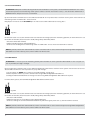
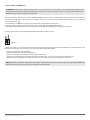
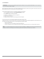
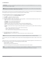
GSM/GPRS COMMUNICATOR ET082 User Manual v1.2 Safety instructions Please read and follow these safety guidelines in order to maintain safety of operators and people around: • GSM/GPRS communicator ET082 (further referenced as system, device or communicator) contains a radio transceiver operating in GSM850/900/1800/1900 bands. • DO NOT use the system where it can interfere with other devices and cause any potential danger. • DO NOT use the system with medical devices if this is required in the manual of the medical device. • DO NOT use the system in hazardous environment. • DO NOT expose the system to high humidity, chemical environment or mechanical impacts. • DO NOT attempt to personally repair the system. • System labelling sticker is at the bottom of the device. System ET082 is a device mounted in limited access areas. Any system repairs must be done only by qualified, safety aware personnel. Mains power must be disconnected before any installation or tuning work starts. The system installation or maintenance must not be done during stormy conditions. The system must be powered by main 10-24V dard and be easily accessible. 300mA power supply which must be approved by LST EN 60950-1 stan- Any additional devices linked to the system ET082 (computer, sensors, relays etc.) must be approved by LST EN 60950-1 standard. External power supply can be connected to AC mains only inside installation room with automatic 2-pole circuit breaker capable of disconnecting circuit in the event of short circuit or over-current condition. Open circuit breaker must have a gap between connections of more than 3mm and the disconnection current is 5A. Phase Null PE AC 230V 50 Hz/DC 24V ET082 USB cable Fuse F1 model - miniSMDC 500mA. Blown fuse cannot be replaced by the user and the replacement fuses have to be exactly the same as indicated by the manufacturer. The device is fully turned off by disconnecting 2-pole switch off device of the external power supply or any other linked device that the system ET082 is powered from. The WEEE (Waste Electrical and Electronic Equipment) marking on this product (see left) or its documentation indicates that the product must not be disposed of together with household waste. To prevent possible harm to human health and/or the environment, the product must be disposed on in an approved and environmentally safe recycling process. For further information on how to dispose of this product correctly, contact the system supplier, or the local authority responsible for waste disposal in your area. Copyright © “ELDES UAB”, 2012. All rights reserved. It is strictly forbidden to copy and distribute information in this document or pass to a third party without an advanced written authorization from “ELDES UAB”. “ELDES UAB” reserves the right to update or modify this document and/or related products without a warning. Hereby, „ELDES UAB“ declares that this GSM/GPRS communicator ET082 is in compliance with the essential requirements and other relevant provisions of Directive 1999/5/ EC. The declaration of conformity may be consulted at www.eldes.lt Limited Liability The buyer must agree that the system will reduce the risk of fire, theft, burglary or other dangers but does not guarantee against such events. “ELDES UAB” will not take any responsibility regarding personal, property or revenue loss while using the system. “ELDES UAB” responsibility according to local laws does not exceed value of the purchased system. “ELDES UAB” is not affiliated with GSM operators providing cellular services, therefore is not responsible for network services, coverage or its operation. Manufacturer Warranty The system carries a 24-month warranty by the manufacturer “ELDES UAB”. Warranty period starts from the day the system has been purchased by the end user. The warranty is valid only if the system has been used as intended, following all guidelines listed in the manual and within specified operating conditions. Receipt with purchase date must be kept as a proof. The warranty is voided if the system has been exposed to mechanical impacts, chemicals, high humidity, fluids, corrosive and hazardous environment or other force majeure factors. Package Content 1. ET082........................................................................qty. 1 2. User manual...........................................................qty. 1 3. GSM antenna.........................................................qty. 1 4. Jumpers...................................................................qty. 4 5. Plastic standoffs....................................................qty. 7 Contents 1. General Information...................................................................... 4 1.1 Operation Description ...............................................................................4 2. Technical Specifications................................................................ 6 2.1 Electrical & Mechanical Specifications...............................................6 2.2 Main Unit, Connector, Pin & LED Functionality ..............................7 2.2.1 Main Unit Functionality.................................................................7 2.2.2 Connector Functionality...............................................................7 2.2.3 Pin Functionality..............................................................................7 2.2.4 LED Functionality.............................................................................7 2.3 Connection Circuit.......................................................................................8 3. Installation..................................................................................... 9 4. Skyrelio pavadinimas..................................................................10 4.1 PSTN Line and GSM Connection Status Monitoring..................... 10 4.2 Inputs & Оutputs........................................................................................ 10 4.3 Remote Configuration of the Alarm System via DTMF................ 10 5. Communication Modes & Methods............................................11 5.1 5.2 5.3 Wiring Diagrams...................................................................................... 11 5.1.1 No PSTN Connection................................................................... 12 5.1.2 With PSTN Connection............................................................... 12 5.1.3 With PSTN Connection through PBX..................................... 13 Basic Mode................................................................................................ 13 5.2.1 Voice Calls Method....................................................................... 14 5.2.2 SMS Method................................................................................... 14 5.2.3 Voice Calls + SMS Method......................................................... 15 5.2.4 GPRS Method................................................................................. 16 Advanced Mode...................................................................................... 17 5.3.1 Voice Calls Method....................................................................... 17 5.3.2 SMS Method................................................................................... 18 5.3.3 GPRS Method................................................................................. 19 5.3.4 CSD Method .................................................................................. 20 6. Configuration & Control..............................................................21 About User Manual This document describes only basic operation and installation of ET082 device. It is very important to read the user manual before starting to use the system. 6.1 Ways of System Configuration........................................................... 21 6.2 Remote System Configuration via GPRS Connection................ 21 6.2.1 Establishing Remote Connection Between ET082 System and Configuration Server......................... 22 6.2.2 Connecting to ELDES Configuration Server using ELDES Configuration Tool Software...................... 22 6.2.3 Ending the Configuration Process..................................... 23 6.3 Configuration Parameter Set (SMS).................................................... 23 7. Technical Support........................................................................27 7.1 Restoring Default Configuration ...................................................... 27 7.2 Upgrading Firmware.............................................................................. 27 7.3 Technical Support................................................................................... 27 8. Related products...........................................................................28 1. General Information Communicator ET082 is a device for transmitting data from alarm system to monitoring station via: • PSTN (telephone landline); • Voice Calls (GSM audio channel); • Voice Calls (GSM audio channel) and/or to users via SMS message; • GPRS network; • CSD (fax line). ET082 main applications & features: • Property security; • Data re-transmission to monitoring station via GSM/GPRS/CSD and/or to preset user via SMS; • Backup connection for PSTN; • PSTN status monitoring in case it is cut-off or disconnected; • Alarm system remote configuration via DTMF. 4 2. Technical Specifications 2.1 Electrical & Mechanical Specifications Power Supply 10-24V Peak Current Consumption 700 mA max. 300mA max Current Used in Standby Mode 120mA max GSM Modem Frequency 850/900/1800/1900 MHz Communications Voice Calls, SMS, GPRS, CSD Supported Protocols Ademco Contact ID®, 4+2, Scancom, EGR100, Kronos, SIA IP Maximum Number of Users Receiving Alarm System Events by SMS Message 5 Maximum Number of Users for Input/Output Control 3 Number of “Low” Level (Negative) Digital Inputs 3 Allowable Input Values Voltage 0... 1.45V; current: 0.8... 0.6mA Input Type NO (normally open) Number of Outputs 3 Output C1 - C3 Circuit 1R OUT Maximum Commuting Output Values Voltage: 30V ; current: 50 mA Dimensions 130 x 73 mm Open collector output. Output is pulled to COM when turned on. Operating temperature range -20...+55oC Generated Phone Line Values Voltage: 18V; current: 25mA; impedance: 600Ω Dial Tone Frequency of Generated Phone line 350 Hz For configurations DEF SIM CARD GSM MODEM SET MODE UART ANT USB INFO STATUS GSM JP9 JP8 F1 L1 L2 L3 L4 RING TIP User manual ELDES ET082 v1.2 C1 DC+ COM C2 Z2 Z1 C3 Z3 COM Fig. No 2 5 2.2 Main Unit, Connector, Pin & LED Functionality 2.2.1 Main Unit Functionality GSM MODEM GSM network 850/900/1800/1900 MHz modem SIM CARD SIM card slot / holder ANT GSM antenna SMA type connector F1 Fuse model – miniSMDC 500mA USB Mini USB port 2.2.2 Connector Functionality Labelling Description L1 - L4 Landline or PBX contacts (according to backup mode) RING RING contact TIP TIP contact C1 - C3 Outputs DC+ Positive power supply contact COM Negative power supply contact / Common contact Z1 - Z3 Inputs 2.2.3 Pin Functionality Labelling Description DEF For restoring factory default settings SET For communication method of Basic mode set up MODE For communication method of Basic mode set up JP8, JP9 For direct data transmission via PSTN with status monitoring UART For retreiving debug log 2.2.4 LED Functionality Labelling Description INFO Operation activity status STATUS Device status GSM GSM network strength GSM Signal Strength Indication GSM signal strength is indicated by GSM LED. To ensure the best quality of the network adjust the position of GSM antenna and find the strongest possible signal by observing the GSM LED indications. GSM LED Indication GSM Signal Strength Off No connection Flashing every 3 seconds The connection is not reliable Flashing every 1 second Satisfactory Flashing several times per second Good On Excellent 6User manual ELDES ET082 v1.0 6 Device Activity Indication STATUS LED Indication Description Off No power supply or some fault is present Flashing several times per second SIM card is not inserted / insterted improperly On Device is operating and ready for use Working Mode Indication INFO LED Indication Description Off Device is in standby mode Flashing several times per second Device retransmits the data sent from alarm system to the monitoring station (this indication is possible when device is operating in communication mode 1) On Device is decoding data to user-understandable text format. 2.3 Connection Circuit ET082 COM connectors of ET082 and alarm system unit must be connected. ET082 inputs Z1 - Z3 are connected to PGM outputs of alarm system unit if PGM output is implemented as open collector circuit or any other circuit and if it commutes with COM. It is also possible to connect motion sensor or any other sensor to ET082 Z1 - Z3 inputs. Zx DC+ COM Cx ET082 C1 - C3 outputs can be connected to the input of electrical appliances if it commutes with COM. This connection allows to control heating, lighting, gates, blinds, water pump etc. PGM ATTENTION: Before connecting ET082 power supply to alarm system's auxiliary output (AUX), please, make sure that the output is able to maintain peak curent consumption of up to 700mA max. Otherwise, please, use an external power supply for ET082. +12V Alarm system or other appliance Fig. No 3 3. Installation The system can be installed in a metal or non-flammable plastic enclosure together with alarm system unti. When the metal enclosure is used it is necessary to ground the enclosure using yellow/green colour cable. For the connection use 0.50 mm2 1 thread cable. For the device connection to input/output connectors use 0.50 mm2 1 thread cable of up to 100 meters length. 1. Place the SIM card into the card holder and make sure that PIN code request is disabled. The PIN code can be disabled by inserting the SIM card into a mobile phone and following proper menu steps. There must be no SMS messages stored in the memory. ATTENTION: The system is NOT compatible with pure 3G SIM cards. Only 2G SIM cards and 3G SIM cards with 2G profile enabled are supported. For more details, please, contact your GSM operator. 2. Connect the GSM antenna to SMA connector. It is not recommended to turn on the device without GSM antenna connec ted. NOTE: It is recommended to install the GSM antenna away from the alarm system to ensure better quality of the audio signal. It is not recommend to install the antenna inside the metal enclosure. 3. Connect the circuit according to desired communication method. For more details, please, refer to chapters 2.3 Connection Circuit & 5.1 Wiring Diagrams 4. The system should start in less than a minute. GSM LED indicator should be blinking or be ON indicating successful con nection to GSM network. NOTE: It is highly recommended to choose the same GSM cellular provider both for users and for ET082 communicator in order to assure fast and reliable SMS message delivery and phone call connection. Note: To ensure maximum system operation reliability we recommend not to use pay-as-you-go SIM cards. If the balance is insufficient the system will not be able to inform users by SMS or send data messages. Important: Power supply at alarm system must be disconnected before any installation or tuning work. 8 4. Operation Description ET082 communicator is a GSM/GPRS device transmitting data from alarm system to monitoring station and/or preset user phone number. The following diagram indicates communication modes & methods supported by the device: USING PSTN? YES NO / PSTN is cut-off Direct data transmission to monitoring station Communication method? PSTN line is being monitored by ET082 in case it is cut-off Set by PCB jumper combination Basic Advanced Set by ELDES Configuration Tool Contact ID Voice Calls Direct channel Converted to userunderstandable text Contact ID SMS Contact ID Scancom Voice Calls Data buffering Contact ID Voice Calls + SMS Primary Direct channel By SMS: converted to user-understandable text SMS Kronos GPRS 1 Contact ID GPRS Converted to user-understandable text EGR100 Backup 1 Contact ID SIA IP Scancom Converted to user-understandable text GPRS 1... 3 Voice Calls EGR100 Data buffering SIA IP Contact ID Kronos Kronos SMS CSD GPRS 1... 3 N/A CSD EGR100 Backup 2 SIA IP EGR100 Contact ID SIA IP Scancom Kronos Voice Calls GPRS 1... 3 Data buffering Converted to user-understandable text Contact ID CSD SMS N/A For more details, please refer to chapter 5. Communication Methods & Modes. User manual ELDES ET082 v1.2 9 4.1 PSTN Line and GSM Connection Status Monitoring The device can also be used for direct data transmission from alarm system to monitoring station via PSTN. This feature allows to monitor the PSTN status and notitify monitoring station and/or preset user in case of PSTN loss/restore events. Depending on the set up communication method and configuration, ET082 can notify by: • sending an SMS message to a preset user (SMS method); • transmitting a data message to monitoring station via GSM audio channel (Voice Calls method); • transmitting a data message to monitoring station via GPRS netowrk (GPRS method); • transmitting a data message to monitoring station via fax line (CSD method). In case of PSTN failures, the communicator switches to the set up communication method and backs up PSTN until it is restored. In addition, the PSTN loss/restore event can also be indicated by SMS message sent to up to 3 preset users or by any output of ET082 device. In case of PSTN or GSM connection failure, the device can turn the output (-s) ON and turn it OFF after the PSTN or GSM is restored. For more details, please refer to ELDES Configuration Tool software‘s HELP section. ET082 can also detect temporary service suspension by the service provider for technical or billing reasons even if a dial tone is still present as “busy” tone. This feature requires an additional audio module which must be requested in advance. 4.2 Inputs & Оutputs ET082 communicator has 3 built-in digital inputs (NO - normally open) for connection to PGM outputs of alarm system or any sensor connection, In case of input alarm/restore event, the communicator sends an SMS message to up to 3 preset user (-s). Built-in open collector outputs allow to connect and control up to 3 electrical appliances. The outputs can be controlled either by SMS message from user who knows the correct SMS password, either automatically in case of PSTN or GSM connection loss/ restore event. The outputs can provide control over heating, lighting, gates, blinds etc. For more details, please, refer to ELDES Configuration Tool software‘s HELP section. 4.3 Remote Configuration of the Alarm System via DTMF ET082 supports a two-way communication providing a possibility for alarm system remote configuration via DTMF. DTMF dialing mode must be supported and enabled in alarm system. 10 5. Communication Modes & Methods ET082 communicator supports Basic and Advanced modes & methods providing a variety of communication protocols. Basic mode is recommended when only one communication method is required while Advanced mode is recommended to use when one or more backup communication methods are required. Please note, that some protocols are not supported in Basic mode and vice versa. COMMUNICATION MODES & METHODS Basic Mode Method Advanced Mode Protocol Method Protocol Voice Calls (GSM audio - direct channel) Ademco Contact ID®, 4+2 Voice Calls (GSM audio - data buffering) Ademco Contact ID®, Scancom SMS (up to 5 users)* Ademco Contact ID® (converted to userunderstandable text) SMS (up to 5 users)* Ademco Contact ID® (converted to userunderstandable text) GPRS (1 destination IP address) EGR100, Kronos, SIA IP GPRS (up to 3 destination IP addresses) EGR100, Kronos, SIA IP Voice Calls (GSM audio - direct channel) + SMS (up to 5 users)* Ademco Contact ID® (by SMS: converted to userunderstandable text) CSD (fax line) * SMS messages are sent to the preset user phone number (-s) set in ELDES Configuration Tool software. 5.1 Wiring Diagrams ATTENTION: Before connecting ET082 power supply to alarm system‘s auxiliary output (AUX), please, make sure that the output is able to maintain peak curent consumption of up to 700mA max. Otherwise, please, use an external power supply for ET082. Before configuring communication methods, the user must decide whether direct data transmission from alarm system to monitoring station via PSTN and PSTN status monitoring is required or not. This is defined by a respective circuit wiring and jumper presence on JP8/JP9 PCB pins. NOTE: PSTN is always a primary (master) connection and it cannot be set as backup when used. User manual ELDES ET082 v1.2 11 5.1.1 No PSTN Connection With this wiring the communicator retransmits data from alarm system to monitoring station by the selected communication method. L1 L2 L3 L4 RING TIP C1 DC+ COM C2 Z2 Z1 JP8 RING/TIP C3 Z3 COM JP9 AUX+ AUX- ALARM SYSTEM Fig. No 4 1. Connect the circuit as indicated in Fig. No. 4– connect telephone contacts of the alarm system RING/TIP to RING/TIP contacts of the communicator. 2. Connect power supply to DC+/COM contacts. Power supply is usually used as AUX- and AUX+ output of alarm system. 3. NO jumpers have to be set on JP8/JP9 pins. 5.1.2 With PSTN Connection With this wiring the communicator retransmits data from alarm system to monitoring station via landline (PSTN). L1 L2 L3 L4 RING TIP C1 DC+ COM C2 Z2 Z1 JP8 To landline (PSTN) RING/TIP C3 Z3 COM JP9 AUX+ AUX- ALARM SYSTEM Fig. No 5 1. Connect the circuit as indicated in Fig. No. 5 – connect telephone contacts of the alarm system RING/TIP to RING/TIP contacts of communicator. 2. Connect L3/L4 contacts to landline (PSTN). 3. Connect power supply to DC+/COM contacts. Power supply is usually used as AUX- and AUX+ output of alarm system. 4. Set the jumpers on JP8 and JP9 pins. 12 5.1.3 With PSTN Connection through PBX F O R A D VA N C E D U S E R S O N LY ! With this wiring the communicator retransmits data from alarm system to monitoring station via landline (PSTN) through private branch exchange station (PBX). To external landline (PSTN) L1 L2 L3 L4 RING TIP C1 DC+ COM C2 Z2 Z1 JP8 RING TIP PBX C3 Z3 COM JP9 AUX+ AUX- ALARM SYSTEM To internal landline (PSTN) Fig. No 6 1. Connect the circuit as indicated in Fig. No. 6 – connect telephone contacts of the alarm system RING/TIP to RING/TIP contacts of communicator. 2. Connect L1/L2 contacts to external landline (PSTN). 3. Connect L3/L4 contacts to internal landline (PSTN) of PBX. 4. Connect power supply to DC+/COM contacts. Power supply is usually used as AUX- and AUX+ output of alarm system. 5. NO jumpers have to be set on JP8/JP9 pins. 5.2 Basic Mode The communication method of Basic mode is selected by jumper position on SET/MODE PCB pins. Basic mode features the following communication methods: • • • • Voice Calls; SMS; Voice Calls + SMS; GPRS. NOTE: The jumper position on SET/MODE PCB pins becomes ineffective as soon as Advanced mode is enabled. User manual ELDES ET082 v1.2 13 5.2.1 Voice Calls Method ATTENTION: DTMF phone number dialing mode must be enabled on alarm system, activated Ademco Contact ID® or 4+2 data transmission protocol and monitoring station phone number set with international code, i.e. For UK London 20xxxxxxxx or 004420xxxxxxxx. The plus character is not allowed. By this method the communicator receives Ademco Contact ID® or 4+2 protocol data sent from alarm system and transmits it to monitoring station via GSM audio – direct channel. NO jumpers have to be set on SET/MODE pins in order to select Voice Calls method. See Fig. No. 7. Fig. No 7 If PSTN connection is used, the communicator also monitors the voltage (dial tone monitoring optional) on the PSTN and in case the PSTN is unavailable, disconnected or cut off (voltage drops below 4V), ET082: • switches to Voice Calls method, • notifies monitoring station about PSTN failure, • continues transmitting data to monitoring station via GSM audio – direct chanel until the PSTN is restored. NOTE: By default, notification about PSTN loss/restore is disabled and has to be enabled if required using ELDES Configuration Tool software. For more details, please, refer to software’s HELP section. 5.2.2 SMS Method ATTENTION: It is necessary to set monitoring station phone number on alarm system for SMS method. In such case you can use any number (one digit is enough). By this method the communicator receives Ademco Contact ID® protocol data sent from alarm system and converts it to user-understandable text which is sent to preset user (-s) by SMS message. 1. Set the jumper on MODE pins in order to select SMS method. See Fig. No. 8. 2. Add user phone number (-s) to the communicator using ELDES Configuration Tool software. 3. Configure Ademco Contact ID® data message structure using ELDES Configuration Tool software if required. For more details, please, refer to ELDES Configuration Tool software’s HELP section. Fig. No 8 If PSTN connection is used, the communicator also monitors the voltage (dial tone monitoring optional) on the PSTN and in case the PSTN is unavailable, disconnected or cut off (voltage drops below 4V), ET082: • switches to SMS method, • notifies the preset user (-s) by SMS message about PSTN failure, • continues sending the converted Ademco Contact ID® by SMS message to preset user (-s) until the PSTN is restored. NOTE: By default, notification about PSTN loss/restore is disabled and has to be enabled if required using ELDES Configuration Tool software. For more details, please, refer to software’s HELP section. 14 5.2.3 Voice Calls + SMS Method ATTENTION: DTMF phone number dialing mode must be enabled on alarm system, activated Ademco Contact ID® data transmission protocol and monitoring station phone number set with international code, i.e. For UK London 20xxxxxxxx or 004420xxxxxxxx. The plus character is not allowed. By this method the communicator receives Ademco Contact ID® protocol data sent from alarm system and transmits it to monitoring station via GSM audio – direct channel. In addition, the data is converted to user-understandable text which is sent to preset user (-s) by SMS message. 1. Set the jumper on SET pins in order to select Voice Calls + SMS method. See Fig. No. 9. 2. Add user phone number (-s) to the communicator using ELDES Configuration Tool software. 3. Configure Ademco Contact ID® data message structure using ELDES Configuration Tool software if required . For more details, please, refer to ELDES Configuration Tool software’s HELP section. Fig. No 9 If PSTN connection is used, the communicator also monitors the voltage (dial tone monitoring optional) on the PSTN and in case the PSTN is unavailable, disconnected or cut off (voltage drops below 4V), ET082: • switches to Voice Calls + SMS method, • notifies monitoring station about PSTN failure, • notifies the preset user (-s) by SMS message about PSTN failure, • continues transmitting data to monitoring station via GSM audio – direct channel until the PSTN is restored, • duplicates and converts data and sends it to preset user (-s) by SMS message until the PSTN is restored. NOTE: By default, notification about PSTN loss/restore is disabled and has to be enabled if required using ELDES Configuration Tool software. For more details, please, refer to software’s HELP section. User manual ELDES ET082 v1.2 15 5.2.4 GPRS Method ATTENTION: It is necessary to set monitoring station phone number on alarm system for GPRS method. In such case you can use any number (one digit is enough). By this method the communicator receives Ademco Contact ID® protocol data sent from alarm system, converts it to EGR100, Kronos or SIA IP protocol data message and transmits it to monitoring station via GPRS network. 1. Set the jumper on SET and MODE pins in order to select GPRS method. See Fig. No. 10. Fig. No 10 2. Set the following ET082 GPRS 1 section parameters using ELDES Configuration Tool software: • APN – Access-point-name provided by GSM operator; • User Name – User name provided by GSM operator; • Password – Password provided by GSM operator; • Server IP – Public IP address of the computer (router) running Kronos/EGR100 software. • Port – Forwarded TCP/UDP port number for the computer running Kronos/EGR100 software. • Protocol – Format of the data message transmitted from ET082 to monitoring station by GPRS method. Available protocols: • Kronos – Kronos LT/Kronos NET monitoring station software data format; • EGR100 – EGR100 GPRS software data format; • SIA IP – SIA/IP data format complying with ANSI/SIA DC-09-2007 standard. 3. Set the following parameters in EGR100 software: • TCP/UDP Server Port - Forwarded port for communication with the device via GPRS connection. NOTE: Port must be set the same both on the communicator using ELDES Configuration Tool and in EGR100 software. For more details, please, refer to EGR100 or Kronos LT/Kronos NET and ELDES Configuration Tool software’s HELP section for more details. If PSTN connection is used, the communicator also monitors the voltage (dial tone monitoring optional) on the PSTN and in case the PSTN is unavailable, disconnected or cut off (voltage drops below 4V), ET082: • switches to GPRS 1... 3 method, • notifies monitoring station about PSTN failure, • continues transmitting data to monitoring station via GPRS network until the PSTN is restored. NOTE: By default, notification about PSTN loss/restore is disabled and has to be enabled if required using ELDES Configuration Tool software. For more details, please, refer to software’s HELP section. 16 5.3 Advanced Mode The communication method (-s) of Advanced mode is selected by ELDES Configuration Tool. Advanced mode features the following communication methods: • • • • Voice Calls; SMS; GPRS; CSD. Advanced mode supports 1 primary and up to 2 backup connections. All of the aforementioned communication methods can be set up as primary or backup in any sequence order. NOTE: The jumper position on SET/MODE PCB pins becomes ineffective as soon as Advanced mode is enabled. 5.3.1 Voice Calls Method ATTENTION: DTMF phone number dialing mode must be enabled on alarm system, activated Ademco Contact ID® or Scancom data transmission protocol and monitoring station phone number set with international code, i.e. For UK London 20xxxxxxxx or 004420xxxxxxxx. The plus character is not allowed. By this method the communicator receives Ademco Contact ID® or Scancom protocol data sent from alarm system, saves it to memory buffer and transmits it to monitoring station via GSM audio channel. Set the following ET082 parameters using ELDES Configuration Tool software: 1. Switch to Advanced mode by enabling Backup Enabled parameter. 2.Select Voice Calls method as Primary connection. 3.Set Backup 1 and Backup 2 connections if required. 4.Select Contact ID or Scancom protocol. By default, Contact ID is selected. For more details, please, refer to ELDES Configuration Tool software’s HELP section. If PSTN connection is used, the communicator also monitors the voltage (dial tone monitoring optional) on the PSTN and in case the PSTN is unavailable, disconnected or cut off (voltage drops below 4V), ET082: • switches to Voice Calls method, • notifies monitoring station about PSTN failure, • continues transmitting data to monitoring station via GSM audio channel with data buffering until the PSTN is restored. NOTE: In case of Voice Calls method failure the communicator switches to Backup 1 and Backup 2 connections (if set) respectively and attempts to continue transmitting data to monitoring station until the previous connection (-s) is restored. User manual ELDES ET082 v1.2 17 5.3.2 SMS Method ATTENTION: It is necessary to set monitoring station phone number on alarm system for SMS method. In such case you can use any number (one digit is enough). By this method the communicator receives Ademco Contact ID® protocol data sent from alarm system and converts it to user-understandable text which is sent to preset user (-s) by SMS message. Set the following ET082 parameters using ELDES Configuration Tool software: 1. Switch to Advanced mode by enabling Backup Enabled parameter. 2. Select SMS method as Primary connection. 3. Set Backup 1 and Backup 2 connections if required. 4.. Add user phone number (-s). 5. Configure Ademco Contact ID® data message structure if required. For more details, please, refer to ELDES Configuration Tool software’s HELP section. If PSTN connection is used, the communicator also monitors the voltage (dial tone monitoring optional) on the PSTN and in case the PSTN is unavailable, disconnected or cut off (voltage drops below 4V), ET082: • switches to SMS method, • notifies the preset user (-s) by SMS message about PSTN failure, • continues sending the converted Ademco Contact ID® by SMS message to preset user (-s) until the PSTN is restored. NOTE: In case of SMS method failure the communicator switches to Backup 1 and Backup 2 connections (if set) respectively and attempts to continue transmitting data to monitoring station until the previous connection (-s) is restored. 18 5.3.3 GPRS Method ATTENTION: It is necessary to set monitoring station phone number on alarm system for GPRS method. In such case you can use any number (one digit is enough). NOTE: GPRS method of Advanced mode supports up to 3 different monitoring station server IP addresses for backup purposes. The IP addresses are set in GPRS 1... GPRS 3 sections respectively. By this method the communicator receives Ademco Contact ID® protocol data sent from alarm system, converts it to EGR100, Kronos or SIA IP protocol data message and transmits it to monitoring station via GPRS network. Set the following ET082 parameters using ELDES Configuration Tool software: 1. Switch to Advanced mode by enabling Backup Enabled parameter. 2. Select GPRS 1... 3 method as Primary connection. 3. Set Backup 1 and Backup 2 connections if required. 4. Set the following GPRS 1... GPRS 3 section parameters referring to GPRS 1... 3 method selected respectively in steps 2 and 3: • APN – Access-point-name provided by GSM operator; • User Name – User name provided by GSM operator; • Password – Password provided by GSM operator; • Server IP – Public IP address of the computer (router) running Kronos/EGR100 software. • Port – Forwarded TCP/UDP port number for the computer running Kronos/EGR100 software. • Protocol – Format of the data message transmitted from ET082 to monitoring station by GPRS method. Available protocols: • Kronos – Kronos LT/Kronos NET monitoring station software data format; • EGR100 – EGR100 GPRS software data format; • SIA IP – SIA/IP data format complying with ANSI/SIA DC-09-2007 standard. 5. Set the following parameters in EGR100 software: • TCP/UDP Server Port - Forwarded port for communication with the device via GPRS connection. NOTE: Port must be set the same both on the communicator using ELDES Configuration Tool and in EGR100 software. For more details, please, refer to EGR100 or Kronos LT/Kronos NET and ELDES Configuration Tool software’s HELP section for more details. If PSTN connection is used, the communicator also monitors the voltage (dial tone monitoring optional) on the PSTN and in case the PSTN is unavailable, disconnected or cut off (voltage drops below 4V), ET082: • switches to GPRS 1... 3 method, • notifies monitoring station about PSTN failure, • continues transmitting data to monitoring station via GPRS network until the PSTN is restored. NOTE: In case of GPRS method failure the communicator switches to Backup 1 and Backup 2 connections (if set) respectively and attempts to continue transmitting data to monitoring station until the previous connection (-s) is restored. User manual ELDES ET082 v1.2 19 5.3.4 CSD Method ATTENTION: It is necessary to set monitoring station phone number on alarm system for CSD method. In such case you can use any number (one digit is enough). By this method the communicator receives Ademco Contact ID® protocol data sent from alarm system, converts it to CSD protocol data message and transmits it to monitoring station via CSD connection. Set the following ET082 parameters using ELDES Configuration Tool software: 1. Switch to Advanced mode by enabling Backup Enabled parameter. 2. Select CSD method as Primary connection. 3. Set Backup 1 and Backup 2 connections if required. 4.. Set CSD monitoring station phone number. For more details, please, refer to ELDES Configuration Tool software’s HELP section. If PSTN connection is used, the communicator also monitors the voltage (dial tone monitoring optional) on the PSTN and in case the PSTN is unavailable, disconnected or cut off (voltage drops below 4V), ET082: • switches to CSD method, • notifies monitoring station about PSTN failure, • continues transmitting data to monitoring station via CSD connection until the PSTN is restored. NOTE: In case of CSD method failure the communicator switches to Backup 1 and Backup 2 connections (if set) respectively and attempts to continue transmitting data to monitoring station until the previous connection (-s) is restored. 20 6. Configuration & Control ATTENTION! In this user manual the underscore _ character represents one space character. There must be no spaces or other characters at the beginning and at the end of the message. XXXX – 4-digit SMS password. ATTENTION! The inputs & outputs can be configured / controlled by any user who knows the correct SMS password. This feature is permanently enabled. The system configuration and control can be performed by sending SMS messages to ET082 phone number, via USB connection locally or via GPRS connection remotely using ELDES Configuration Tool software which is recommended for quick and convenient system configuration. 6.1 Ways of System Configuration In order to configure and control the system by SMS message, send the text command to the ET082 system phone number from one of the preset user phone numbers. The structure of SMS message consists of 4 digit SMS password (the default SMS password is 0000 – four zeros), the parameter and value. For some parameters the value does not apply, i.e. STATUS. Software ELDES Configuration Tool is intended to work directly with ET082 system, which can be connected to the computer via USB port or via GPRS connection remotely. This software simplifies system configuration process by allowing to use a personal computer in the process. Before starting to use ELDES Configuration Tool, please read user guide available in the software’s HELP section. ELDES Configuration Tool is freeware and can be downloaded from ELDES website at: www.eldes.lt 6.2 Remote System Configuration via GPRS Connection ATTENTION! The system will NOT send any data to monitoring station while configuring the system remotely via GPRS network. However, during the configuration session, the data messages are queued up and transmitted to the monitoring station after the configuration session is over. Before configuring ET082 remotely via GPRS connection, make sure that: • SIM card is inserted into ET082 device. • Mobile internet service is enabled on the SIM card. • Power supply is connected to ET082. • Default SMS password is changed to a new 4-digit password; • At least User1 phone number is set up. User manual ELDES ET082 v1.2 21 6.2.1 Establishing Remote Connection Between ET082 System and Configuration Server Initiate the Connection to ELDES Server In order to activate a remote GPRS connection between ET082 system and ELDES configuration server please , send the following SMS message from user phone number. Upon the successful SMS message delivery, the system establishes a connection session for 20 minutes. An SMS reply, containing device IMEI number and confirming a successful connection establishment, is sent shortly. SMS text: XXXX_STCONFIG Example: 1111_STCONFIG Initiate the Connection to Third-Party Server In case it is necessary to establish a connection between ET082 system and a third-party configuration server, send the following SMS message. SMS text: XXXX_STCONFIG:IPaddress:Port or XXXX_ STCONFIG:HostName:Port Value: Ipaddress – public IP address of third-party configuration server; Port – port number of third-party configuration server, HostName - public host-name of third-party configuration server. Example: 1111_STCONFIG:62.80.115.102:4522 NOTE: Public IP address (host-name) and port number are necessary when connecting to a third-party-server for the first time only. When connecting to the server next time, XXXX_stconfig is enough as the IP address (host-name) and port number are saved in the device memory after the first successful connection. 6.2.2 Connecting to ELDES Configuration Server using ELDES Configuration Tool Software 5.3.2.1 Run ELDES Configuration Tool software. 5.3.2.2 Press Remote Configuration button. 5.3.2.3 In the next window, select Connect to Remote Server (recommended) and press Next button. 5.3.2.4 Enter the received IMEI number in Device IMEI entry. 5.3.2.5 Press Continue button. 5.3.2.6 Upon the successfully established connection, the system prompts for an administrator password. 5.3.2.7 By entering a valid administrator password, the sys tem grants access to full configuration remotely. 5.3.2.8 Remote Configuration Management window displays all performed configuration actions. 22 6.2.3 Ending the Configuration Process Shut down the Connection with the Server After the system configuration is complete, use one of the following methods to end the configuration process: - Press Disconnect button and close ELDES Configuration Tool software; - Wait for the system to reply with an SMS message confirming the end of the session; - Shut down the connection with the server at any time by sending an SMS message. SMS text: XXXX_ENDCONFIG Example: 1111_ENDCONFIG 6.3 Configuration Parameter Set (SMS) Status SMS report indicating information on system input and output status. SMS text: XXXX_STATUS Example: 1111_STATUS Set SMS Password The 4-digit SMS password intended for system configuration and control by SMS messages. By default, the SMS password is 0000 (four zeros) which is recommended to change. SMS text: 0000_PSW:XXXX Value: XXXX – new 4-digit SMS password. Example: 0000_PSW:1111 Set User Phone Number The system supports up to 3 phone number entries allowing to receive input alarm and restore texts by SMS. User 1 phone number is mandatory while other phone number entries are not necessary. All numbers must be entered starting with international country code e.g. 44[area code][local number]. The plus symbol is not necessary. SMS text: XXXX_NRx:3701111111 Value: NRx: - user phone number entry, range - [NR1... NR3] Example: 1111_NR1:37062222222 User manual ELDES ET082 v1.2 23 Set Input Alarm Text Each input has an alarm text which is sent by SMS message to a preset user (-s) in case the input is violated. Manufacturer default input alarm text: Z1 - Input 1 TRIGGERED, Z2 - Input 2 TRIGGERED, Z3 - Input 3 TRIGGERED. This command sets an alarm text for a specified input. Maximum allowed length is 23 characters including space characters. SMS text: XXXX_TZx:ON:NewAlarmText Value: TZx - input number, range - [TZ1... TZ3]. Example: 1111_TZ3:ON:Sensor violated Set Input Restore Text Each input has a restore text which is sent by SMS message to a preset user (-s) in case the input is restored. Manufacturer default input restore texts: Z1 - Input 1 RESTORED, Z2 - Input 2 RESTORED, Z3 - Input 3 RESTORED. This command sets a restore text for a specified input. Maximum allowed length is 23 charac ters including space characters. SMS text: XXXX_TZx:OFF:NewAlarmText Value: TZx - input number, range - [TZ1... TZ3]. Example: 1111_TZ3:OFF:Sensor restored Disable Input This command disables a specified input. By default, all inputs are enabled. SMS text: XXXX_Zx:OFF Value: Zx - input number, range - [Z1... Z3] Example: 1111_Z3:OFF 24 Enable Input This command enables a specified input. SMS text: XXXX_Zx:ON Value: Zx - input number, range - [Z1... Z3] Example: 1111_Z1:ON Set Output Name Each output has an name which is sent by SMS to a preset user (-s). Manufacturer default output names: C1 - Output1, C2 - Output2, C3 - Output3. This command sets at name for a specified output. Maximum allowed length is 23 characters. SMS text: XXXX_TCx:NewOutputName Value: TCx - output number, range - [TC1... TC3]. Example: 1111_TC2:Pump Turn ON Output This command turns on a specified output. SMS text: XXXX_Cx:ON or XXXX_OutputName:ON Value: Cx - output number, range - [C1... C3] Example: 1111_Pump:ON Turn OFF Output This command turns off a specified output. SMS text: XXXX_Cx:OFF or XXXX_OutputName:OFF Value: Cx - output number, range - [C1... C3] Example: 1111_C1:OFF User manual ELDES ET082 v1.2 25 Turn ON Output by Pulse This command switches the output ON for a set period of time and switches the output back to OFF after the set period of time is over. SMS text: XXXX_Cx:ON:T or XXXX_OutputName:ON:T Value: T – period of time in seconds, range - [1-9999] Example: 1111_C3:ON:75 Turn OFF Output by Pulse This command switches the output OFF for a set period of time and switches the output back to ON after the set period of time is over. SMS text: XXXX_Cx:OFF:T or XXXX_OutputName:OFF:T Value: T – period of time in seconds, range - [1-9999] Example: 1111_Pump:OFF:50 Telephone Line Failure/Restore Delay The delay period of time between telephone line failure and restore events. If telephone line failure and restore events occur before the set delay period of time is over, the system will not send the SMS report. SMS text: XXXX_TELDLY:T Value: T – period of time in seconds, range - [1-250] List SMS Message Structure This command provides a list of SMS message structure examples supported by ET082. SMS text: XXXX_HELP Example: 1111_HELP 26 7. Technical Support 7.1 Restoring Default Configuration To restore the parameters to default values: 1. 2. 3. 4. 5. 6. Disconnect the power supply; Short circuit (connect) DEF pins; Power up ET082 for 7 seconds; Disconnect the power supply; Remove short circuit from DEF pins; Parameters restored to default. 7.2 Upgrading Firmware 1. Disconnect the power supply and backup battery. 2. Short circuit (connect) DEF pins. 3. Connect the device via USB cable to the PC. 4. Power up the device. 5. The new window must pop-up where you will find the .bin file. Otherwise open My Computer and look for Boot Disk drive. 6. Delete the .bin file found in the drive. 7. Copy the new firmware .bin file to the very same window. 8. Power down the device. 9. Unplug USB cable. 10. Remove short circuit from DEF pins. 11. Power up the device. 12. Firmware upgraded. NOTE: It is strongly recommended to restore parameters to default values after the firmware upgrade process. 7.3 Technical Support Indication Possible Reason GSM LED is off or not flashing • • • • No external power supply Circuit not properly connected Blown fuse No GSM network signal STATUS LED flashing several times per second • • • SIM card not inserted / improperly inserted PIN code enabled SIM card inactive System does not send any SMS messages • • • • SIM card credit limit exceeded Incorrect SMS centre phone number No GSM network signal User phone number is not preset. Received SMS message “Wrong syntax“ or “Command is not correct“ • • Incorrect syntax Extra <space> character is left in SMS message For product warranty repair service, please, contact your local retail store where this product was purchase. If your problem could not be fixed by the self-guide above, please, contact your distributor or ELDES technical support by email [email protected] More up to date information about your device and other products can be found at the manufacturer‘s website www.eldes.lt User manual ELDES ET082 v1.2 27 8. Related products ET08P plastic enclosure Power supply 28 User manual ELDES ET082 v1.2 29 Made in Lithuania. www.eldes.lt