1
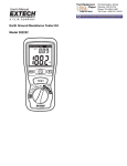
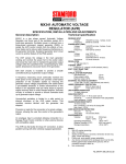
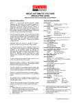
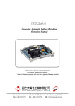
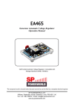
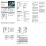
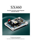
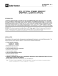
Automatic voltage regulator
EVC600C User Manual
EVC600C User Manual
Ver 1.0
Date: 2014/07/31
EVC600C SERIES
Version
Date
Version
2014-07-31
1.0
http://www.engga.com.cn
Note
Original release
Page 1 of 6
Automatic voltage regulator
EVC600C User Manual
Introduction
EVC600C Automatic Voltage Regulator(AVR)is
alternator output voltage regulating equipment, its
design is based on half-wave phase-controlled
rectifier principles and our company generator
excitation characteristics. It can be used for the
auxiliary winding, phase power Excitation Generator.
The feature is high stability, fast response, easy
installation and maintenance, etc.
Specifications
Output
Volatage: Max 96V @220Vac
Continual current :8A
Max transient current:10A,≤10 second
Field winding resistance
Min. 9Ω
Power input voltage (AC)
180~250Vac,50/60Hz
Power :Max 1000VA(240 Vac)
Sense voltage (AC)
180~250Vac(220Vac System)single phase,
50/60 Hz;
350~480Vac(400Vac System)single phase,
50/60 Hz;
Power consumption: 5 VA
Voltage adjustment range
180~300 Vac ;350~500Vac
Regulation ±1%
Thermal drift <0.05% /℃
Response time 1.5s
Build voltage
The generator remaining excitation voltage will build
voltage automatically,5Vac、25Hz
Power consumption: Max 40W
Quadrature droop input
CT:rated current ratio is 5A, Droop
0 ~6%,0.8 power factor
Operating temperature
-30ºC ~ +80ºC
Relative humidity 95%
Vibration
12 Gs,5~26 Hz;
0.036 inch amplitude,27~52 Hz;
5.0 Gs,53~1000 Hz
Impugnable
Above three orthogonal planes is 20 Gs
Weight
Net weight : 0.62 kg
Installation
Use M4 bolts installed in the
generator terminal box
(Dimensions in the Picture 1)
http://www.engga.com.cn
Operating Instructions
Jumper selection
(1) when generator capacity is less than 90KW,STABLITY set to A-C,
(2) when generator capacity is between 90-550KW,STABLITY set to B-C,
(3) when generator capacity is more than 550KW,STABLITY set to A-B,
(4) when rated frequency is 50Hz,FREQUENCY set to 50;
when rated frequency is 60Hz,FREQUENCY set to 60.
Voltage(VOLT) ---Adjust the generator output voltage
The generator output voltage can be adjusted according to the
characteristics of the generator set, usually, the built-in voltage
adjustment potentiometer “VOLT” can adjust a big range of
voltage(350~480 V or 180 ~300V),If you want to adjust the
voltage from the control panel or screen,you can connect a
suitable potentiometer to VR1 and VR2 terminal(Mini power
2W,Resistance is 10 KΩ-100KΩ).
Voltage rise
Stability(STAB)
The voltage regulator provides a built-in stable adjustment
circuit,wide range of applications,This operation can set the field
winding’s react, to meet the characteristics of the factories and
different engines. (Such as diesel engine, turbine), get the best
voltage response, change the stability characteristics of the
regulator needs to be set by STAB potentiometer on the regulator.
Increase response time, improve stability
LF protection(UFRO)---low-speed protection settings
Usually, the factory’s setting is in order to reduce the generator
excition current when the generator speed is lower than 95%
rated speed of the generator,Adjust the protection point’s speed
via adjust the potentiometer UFRO.Such as:Rated frequency
50Hz set the LF protection point 47Hz,Rated frequency 60Hz set
the LF protection point 57Hz
Note:The factory has been set up, please do not adjust again
Reduce the protection point’s speed
Parallel compensation (DROOP)
The voltage regulator is suit for two similar generators operating in
parallel, provide the total reactive power to all generators in
parallel running, and makes correct allocation, can achieved it via
a external 5A current transformer to sense the generator U-phase
current and a build-in voltage regulator DROOP circuit.
The voltage regulator provides two inputs S1 and S2 are
connected to the current transformers. When the generator is
running in stand-alone, these terminals are usually shorted.
Clockwise increases the amount of C.T. signal injected into the
AVR and increases the droop with lagging power factor (cos Ø).
With the control fully anti-clockwise there is no DROOP. CT
detection signal and the voltage regulator phase sequence must
be correct, otherwise, the generator would not normally work in
parallel. CT must be installed in different phases and the detection
of the detection voltage.
Increase DROOP sensitivity
Page 2 of 6
Automatic voltage regulator
EVC600C User Manual
Level of sensitivity(TRIM)
An analogue input (A1 A2) is provided to connect to the Newage Power Factor Controller or other
devices. It is designed to accept dc signals up to +/- 5 volts.
Increase sensitivity
Picture 1.
Wiring
Such as Picture 2, 3,4
1、VR1、VR2 is remote voltage adjustment terminal. When you
need to adjust the voltage remotely,can connect a
10KΩ-100KΩ 2W potentiometer between VR1、
VR2;otherwise,must be shorted.
2、F+、F- is excitation outputs, connect the field winding inputs
3、X1、X2 is power supply inputs,can connect an auxiliary
winding, phase power supply, etc.
4、V0、V220、V380 is detection signal inputs, connect to output
terminal line voltage of generator,400Vac system generator
output line voltage connect to V0 and V380 (Picture 2 as a
reference);220Vac system generator output line voltage
connect to V0 and V220 (Picture 3 as a reference).
5、S1、S2 is current compensation input terminal, when parallel
operation, current transformer ratio is In/5A,capacity is 5VA
droop current transformer (CT)’s output terminal,If the
direction of rotation of the generator is A-B-C,The generator
S1 connect to CT’s positive,S2 connect to CT’s negative;If
the direction of rotation of the generator is,must reverse.
(Note: CT must install on the generator output terminal,
the phase line which one not provides the signals to the
voltage regulator).
6、A1 、A2 is voltage adjustment inputs.can connect the
external ±5Vd, Each 1Vdc can adjust 5% generator terminal
voltage, pay attention to the polarity when connect.
http://www.engga.com.cn
Build-up excition
When the first start of the regulator and generator,
maybe the residual magnetism can’t reach the
start-up requirement of the regulator, we need to
do as following steps:
a、Prime mover in a stopped state, use a DC power
supply, don’t higher than 12Vdc, connect to the
generator E1, E2, magnetizing to the generator,
please pay attention to that the polarity, the
power supply ’ s positive pole connect E1,
negative pole connect to E2.
b、Build-up excition about 2s after power ups;
c、After finished the a and b steps, if the voltage is
still not established, please check the DC power
supply
Test
EVC600C Performance tests and operation
steps(Picture 4 for reference)
1、Adjust the VOLT potentiometer clockwise to the
MAX, the bulb should be off;
2、Adjust the VOLT potentiometer counterclockwise
to the MAX, the bulb should be light;
3 、 VOLT potentiometer,can control the bulb just
beginning to shine.
Page 3 of 6
Automatic voltage regulator
EVC600C User Manual
1、S1、S2 is current reactive power compensation input terminal, when parallel operation, current transformer r
atio is In/5A.
2、A1 、A2 voltage regulator inputs,can connect the external ±5Vdc.
3 、 If need to adjust the voltage remotely,can connect a 10-100KΩ / 1W potentiometer between VR1, VR2,
otherwise,MUST BE SHORTED!
Picture 2. 400V system self-motivation wiring diagram
http://www.engga.com.cn
Page 4 of 6
Automatic voltage regulator
EVC600C User Manual
1、S1、S2 is current reactive power compensation input terminal, when parallel operation, current transformer r
atio is In/5A.
2、A1 、A2 voltage regulator inputs,can connect the external ±5Vdc.
3 、 If need to adjust the voltage remotely,can connect a 10-100KΩ / 1W potentiometer between VR1, VR2,
otherwise,MUST BE SHORTED!
Picture 3. 200V system self-motivation wiring diagram
http://www.engga.com.cn
Page 5 of 6
Automatic voltage regulator
EVC600C User Manual
Picture 4, VOLT knob on the back of the product can adjust
the voltage (refer to above picture)
Picture 4.Test wiring diagram
1、Output frequency 50Hz/60Hz can be adjusted via “FREQUENCY”.
2、The above two curves were EVC600C 50Hz and 60Hz output frequency’s low-frequency protection action curves.
Picture 5.generator frequency-output voltage relation(400V system)
http://www.engga.com.cn
Page 6 of 6