1
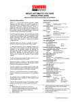
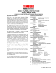
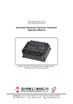
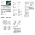
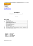
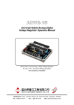
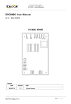
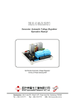
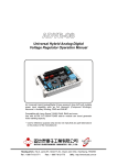
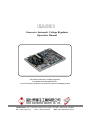
EA321 Generator Automatic Voltage Regulator Operation Manual Self Excited Automatic Voltage Regulator Compatible with Newage MX321* * Use for reference purpose only and not a genuine Newage product. Headquarters : No.3, Lane 201, Chien Fu St., Chyan Jenn Dist., Kaohsiung, TAIWAN Tel : + 886-7-8121771 Fax : + 886-7-8121775 URL : http://www.kutai.com.tw 1. SPECIFICATION Sensing Input Voltage Frequency 190 ~ 264 VAC Max, 3 phase 50 / 60 Hz, selectable Power Input (PMG) Voltage 170 ~ 220 VAC Max, 3 phase 3 wire Current 3A / Phase Frequency 100 ~ 120 Hz, nominal Output Voltage Current Resistance Max. 120 VDC Continuous 4A Intermittent 7A for 60 sec Min. 15 ohm Voltage Regulation < ± 0.5% RMS ( with 4% engine governing ) Voltage Build-up Residual voltage at AVR terminal > 5 VAC Thermal Drift 0.05% per C change in AVR ambient External Volt Adjustment ± 10% with 5K ohm 1 watt trimmer Unit Power Dissipation Max. 18 watt Under Frequency Protection (Factory Setting) Set point 95% Hz Slope 100 ~ 300% down to 30 Hz Current Limit Input 10 ohms burden Sensitivity range Soft Start Ramp Time 0.4 ~ 4 sec. Analogue Input Input Resistance Sensitivity Max. Input 1K ohm 1V for 5% generator volt ± 5 VDC Quadrature Droop Input Burden 10 ohm Max. sensitivity 0.22 A for 5% droop (PF=0) Max. input 0.33 A Over Voltage Detector Input Set point 300V. Time delay 1 sec (fixed) CB trip coil volt 10 ~ 30 VDC / 0.5 Amp CB trip coil resistance 20 ~ 60 ohms Over Excitation Protection Set point 120 VDC Time delay 8 ~ 15 sec Typical System Response AVR response 10 ms Filed current to 90% 80 ms Machine volt to 97% 300 ms Environmental 100Hz ~ 2K Hz 3.3g Relative humidity 0 ~ 70 C 95% (see note 7) Operating temperature -40 ~ 70 C Storage temperature -40 ~ 85 C Dimensions 203mm L * 153mm W * 45mm H 0.5 ~ 1A Weight 530g ± 2% 2. GENERAL DESCRIPTION ● The AVR senses the voltage in the main ● EA321 is a three phase sensed Automatic generator winding and controls the power fed to Voltage Regulator and forms part of the the exciter stator and hence the main rotor to excitation system for a brush-less generator. maintain the generator output voltage within the Excitation power is derived from a three-phase specified limits, compensating for load, speed, permanent magnet generator (PMG), to isolate temperature and power factor of the generator. the AVR control circuits from the effects of nonlinear loads and to reduce radio frequency ● Soft start circuitry is included to provide a smooth interference on the generator terminals. controlled build up of generator output voltage. Sustained generator short circuit current is another feature of the PMG system. ______________________________________________________________________________________ 2 EA321 ● A frequency measuring circuit continually monitors the shaft speed of the generator and provides under-speed protection of the excitation system by reducing the generator output voltage proportionally with speed below a pre-settable threshold. A further enhancement of this feature is an adjustable volt per Hertz slope to improve engine recovery time on turbo charged engines. Soft start circuitry is included to provide a smooth controlled build up of generator output voltage. ● Uncontrolled excitation is limited to a safe period by internal shutdown of the AVR output device. This condition remains latched until the generator has stopped. ● Provision is made for the connection of a remote voltage trimmer, allowing the user fine control of the generator’s output. ● An analogue input is provided allowing connection to a controller or other external devices with compatible output. ● The AVR has the facility for droop CT connection, to allow parallel running with other similarly equipped generators. NOTE : 1. Derate linearly from 3.7A at 50 C to 2.7A at 70 C. 2. The stated voltage regulation may not be maintained in the presence of certain transmitted radio signals. Any change in regulation will fall within the limits in criteria B of S.EN.61000-6-2 : 2001. 3. After 10 minutes. 4. Applies to Mod status E onwards. Generator de-rate may apply. Check with factory. Factory set, semi-sealed, jumper selectable. 5. Any device connected to the analogue input must be fully looting (galvanically isolated from ground), with an insulation strength of 500Vac. 6. Non condensing. 3. SUMMARY OF AVR CONTROLS CONTROL VOLT STABILITY UFRO DROOP TRIM EXC DIP DWELL I LIMIT OVER V RAMP RMS FUNCTION To adjust generator output voltage To prevent voltage hunting To set the UFRO knee point To set the generator droop to 5% at 0pf To optimize analogue input sensitivity To set the over excitation cut off level To set the frequency related voltage dip To set the HZ related recovery time To set the stator current limit To set the over voltage trip level To set the no load voltage RAMP up time To set 3 phase RMS detected 4. ADJUSTMENT OF AVR CONTROLS 4.1 Voltage Adjustment The generator output voltage is set at the factory, but can be altered by careful adjustment of the VOLT control on the AVR board, or by the external hand trimmer if fitted. Terminals 1 and 2 on the AVR will be fitted with a shorting link if no hand trimmer is required. DIRECTION Clockwise increases output voltage Clockwise increase the damping effect Clockwise reduces the knee point frequency Clockwise increases the droop Clockwise increases the gain or sensitivity Clockwise increase the cut off level Clockwise increases the voltage dip Clockwise increases the recovery time Clockwise increases the current limit Clockwise increases the trip level Clockwise increases the voltage ramp time WARNING Do not increase the voltage above the rated generator voltage. If in doubt, refer to the rating plate mounted on the generator case. Do not ground any of the hand trimmer terminals, as these could be above earth potential. Failure to observe this could cause equipment damage. If a replacement AVR has been fitted or re-setting of the VOLT adjustment is required, proceed as follows : ______________________________________________________________________________________ EA321 3 1. Before running generator, turn the VOLT control fully anti-clockwise. 2. Turn remote VOLT trimmer (if fitted) to midway position. 50Hz system or 57Hz on a 60Hz system. 4.4 DROOP Adjustment 6. If the red Light Emitting Diode (LED) is illuminated, refer to the Under Frequency Roll Off (UFRO) adjustment.. Generators intended for parallel operation are fitted with a quadrature droop C.T. which provides a power factor dependent signal for the AVR. The C.T. is connected to S1, S2 on the AVR, (see generator wiring diagram for details). The DROOP adjustment is normally preset in the works to give 5% voltage droop at full load zero power factors. Clockwise increases the amount of C.T. signal injected into the AVR and increases the droop with lagging power factor (cos Ø ). With the control fully anti-clockwise there is no droop. 7. Carefully turn VOLT control clockwise until rated voltage is reached. 4.5 Trim Adjustment 8. If instability is present at rated voltage, refer to stability adjustment, then re-adjust voltage if necessary. ● An analogue input (A1 A2) is provided to connect to the controller or other devices. It is designed to accept dc signals up to ±5 VOLT. 9. Voltage adjustment is now completed. ● The dc signal applied to this input adds to the AVR sensing circuit. A1 is connected to the AVR 0 VOLT. Positive on A2 increases excitation. Negative on A2 decreases excitation. 3. Turn STABILITY control to midway position. 4. Connect a suitable voltmeter (0~300Vac) across line to neutral of the generator. 5. Start generator set, and run on no load at nominal frequency e.g. 50~53Hz or 60~63Hz. 4.2 Stability Adjustment ● The AVR includes stability or damping circuit to provide good steady state and transient performance of the generator. ● A jumper link selector is provided to optimize the response of the stability circuit to various size generators. ● The link should be positioned as shown in the diagram according to the KW rating of the generator. The correct setting of the Stability adjustment can be found by running the generator at no load and slowly turning the stability control anti-clockwise until the generator voltage starts to become unstable. The optimum or critically damped position is slightly clockwise from this point (i.e. where the machine volt are stable but close to the unstable region). 4.3 Under Frequency Roll Off (UFRO) Adjustment The AVR incorporates an under-speed protection circuit which gives a VOLT / Hz characteristic when the generator speed falls below a presentable threshold known as the “knee” point. The red Light Emitting Diode (LED) gives indication that the UFRO circuit is operating. ● The TRIM control allows the user to adjust the sensitivity of the input. With TRIM fully anti-clockwise the externally applied signal has no effect. Clockwise it has maximum effect. ● Normal setting is fully clockwise when used with a controller. WARNING Any devices connected to this input must be fully floating and galvanically isolated from ground, with an insulation capability of 500Vac. Failure to observe this could result in equipment damage. 4.6 Excitation (EXC) Adjustment This adjustment is set and sealed in the works and should not be tampered with. An over excitation condition is indicated by the illumination of the red LED which also indicates under-speed running and over-volt. The generator must be stopped to reset an over-excitation trip. 4.7 DIP Adjustment The UFRO adjustment is preset and sealed and only requires the selection of 50 or 60Hz and 4 pole or 6 pole, using the jumper link as shown in the diagram. For optimum setting, the LED should illuminate as the frequency falls just below nominal, i.e. 47Hz on a This feature is mostly used when the generator is coupled to turbo charged engines with limited block load acceptance. The feature works by increasing the V/Hz slope to give greater voltage roll off in proportion to speed. ______________________________________________________________________________________ 4 EA321 With the DIP control fully anti-clockwise, the generator voltage will follow the normal V/Hz line as the speed falls below nominal. Turning the DIP control clockwise provides greater voltage roll off aiding engine recovery. to be connected to the AVR S1 S2 terminals. There is an internal time limit of 10 seconds. Consult the factory before using this feature. 4.8 RMS Voltage Adjustment This adjustment is set and sealed in the works and should not be tampered with. An over voltage condition is indicated by the illumination of the red LED which also indicates under-speed running and over-excitation. The generator must be stopped to reset an over-voltage trip. 4.11 Over Voltage (OVER V) Adjustment When the generator is operating with a relatively low power factor load, or other reasons change the output power waveform when adding load, this will then cause the AVR sensing the deviated voltage. The RMS control on the AVR can reduce the voltage variations caused by the output waveform changes. This improves voltage regulation. 4.12 RAMP The AVR includes a soft start or voltage ramp-up circuit to control the rate of voltage build up, when the generator runs up to speed. This is normally pre-set and sealed to give a voltage ramp-up time of approximately 3 seconds. If required, this can be adjusted between the limits defined in the specification. 4.9 DWELL This feature is mostly used when the generator is coupled to turbo charged engines with limited block load acceptance. The feature works by introducing a delay between speed recovery and voltage recovery and allows a greater DIP setting without instability. WARNING With the DWELL control fully anti-clockwise, the generator voltage will follow the V/Hz line. Turning the DWELL control clockwise increase the delay time between speed recovery and voltage recovery. Please make sure you have read and understand the contents of the instruction manual prior to installation. Incorrect wiring connection may result in irreversible damage to the product and other equipments. 4.10 Current Limit (I LIMIT) Adjustment This feature is mostly used to limit short circuit current or to provide a current limit on motor starting. To use this feature, current limit CT’s of the correct ratio need 5. FITTING AND OPERATING ( Refer to generator wiring diagram for connection details ) 153.6 43.5 129.6 20.0 ATTENTION Resistor 1. Leave sufficient space for the high output resistor to dissipate heat. Install the AVR with an up right position where the high output resistor is above heat sink. Resistor OVER / V 65.0 RAMP 2. AVR can be mounted directly on the engine, genset, switchgear, control panel, or any position that will not affects operation. For dimension reference, please see Figure 1. 203.5 EXC. TRIP LED DWELL INDICATOR 114.5 DIP STABILITY UFRO RMS DROOP VOLTS TRIM I/LIMIT 5.5 3. All voltage readings are to be taken with an average-reading voltmeter Meggers and high-potential test equipment must not be used. Use of such equipment could damage the AVR. Figure 1 Outline Drawing ______________________________________________________________________________________ EA321 5 Volts K2 K1 P2 P3 P4 XX 6 X 7 Ramp 8 2 No link 6P50HZ 6P60HZ 4P50HZ 4P60HZ UFRO I Limit Frequency Selection 3 2 1 Indicator LED Dip EA321 1 Rms Dwell Stability >550KW 90-550KW <90KW Stability Exc. Selection Over V E0 E1 B0 B1 C B A U S1 S2 V W S1 S2 Droop S1 S2 A1 A2 Trim Figure 2 Exciter PMG Disposition Drawing 3O Bridge 220V Generator C.T R C.T G S ~ C.T T P2 P3 P4 XX X E0 E1 6 7 8 EA321 K1 K2 B0 B1 2 1 S1 S2 S1 1 2 S2 S1 V U 3 S2 W A B C 5K For external adjusted Figure 3 Wiring Drawing Note : When the system voltage over 220VAC, a transformer is necessary at sensing input terminal is recommend. ※ Appearance and specifications of products are subject to change for improvement without prior notice. ______________________________________________________________________________________ 6 EA321