1
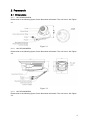
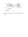
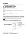
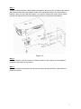
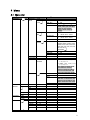
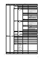
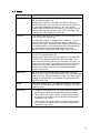
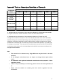
HD Analog Camera User’s Manual
Version 1.0.0
Table of Contents
1
2
General Introduction ..................................................................................................................1
1.1
Overview ........................................................................................................................1
1.2
Features.........................................................................................................................1
1.3
Functions .......................................................................................................................1
1.4
Specifications ................................................................................................................2
Framework...................................................................................................................................4
2.1
Dimensions....................................................................................................................4
2.1.1 HAC-HDW2200SP/N ............................................................................................4
2.1.2 HAC-HFW2200BP/N ............................................................................................4
2.1.3 HAC-HFW2200DP/N ............................................................................................4
3
4
Installation ...................................................................................................................................6
3.1
Dome Camera Installation Introduction ....................................................................6
3.2
Fixed Camera Installation ...........................................................................................6
Menu.............................................................................................................................................8
4.1
Menu List .......................................................................................................................8
4.2
Note ..............................................................................................................................10
Appendix Toxic or Hazardous Materials or Elements ...............................................................11
i
Welcome
Thank you for purchasing our analog camera!
This user’s manual is designed to be a reference tool for your system.
Please read the following safeguard and warnings carefully before you use this series product!
Please keep this user’s manual well for future reference!
ii
Important Safeguards and Warnings
1.Electrical safety
All installation and operation here should conform to your local electrical safety codes.
The power shall conform to the requirement in the SELV (Safety Extra Low Voltage) and the Limited
power source is rated 12V DC in the IEC60950-1.
We assume no liability or responsibility for all the fires or electrical shock caused by improper handling
or installation.
2.Transportation security
Heavy stress, violent vibration or water splash are not allowed during transportation, storage and
installation.
3.Installation
Do not apply power to the camera before completing installation.
Please install the proper power cut-off device during the installation connection.
Always follow the instruction guide the manufacturer recommended.
If this product is installed in the ceiling, please make sure the installation position can sustain the min
50N.
4.Qualified engineers needed
All the examination and repair work should be done by the qualified service engineers.
We are not liable for any problems caused by unauthorized modifications or attempted repair.
5.Environment
This series analog camera should be installed in a cool, dry place away from direct sunlight or strong
light, inflammable, explosive substances and etc.
The working temperature ranges from -30℃ to +60℃. Please keep it away from the electromagnetic
radiation object and environment.
Please make sure the CMOS component is out of the radiation of the laser beam device. Otherwise it
may result in CMOS optical component damage.
Please keep the sound ventilation.
Do not allow the water and other liquid falling into the camera.
6. Accessories
Be sure to use all the accessories recommended by manufacturer.
Before installation, please open the package and check all the components are included.
Contact your local retailer ASAP if something is broken in your package.
7. Daily Maintenance
iii
Please shut down the device and then unplug the power cable before you begin daily maintenance
work.
Use the dry soft cloth to clean the device. If there is too much dust, please use the water to dilute the
mild detergent first and then use it to clean the device. Finally use the dry cloth to clean the device.
Please put the dustproof cap to protect the CMOS component when you do not use the camera.
iv
1 General Introduction
1.1 Overview
This series megapixel analog HD camera conforms to the HDCVI standard. It supports video
signal high-speed long distance transmission without any delay. It can be controlled by the
DVR conforming to the HDCVI.
1.2 Features
z
z
z
z
z
z
z
z
z
z
z
z
z
High-performance CMOS image sensor, megapixel definition.
HD video, coaxial cable to transmit the control signal.
Support 75-3 coaxial cable transmission without any loss. Transmission distance is over
300m.
Support analog HD and standard definition switch.
Support 1080P@25, 1080P@30, 720P@25, 720P@30, 720P@50, 720P@60.
High speed, long distance real-time transmission.
Support OSD (on-screen display), suitable for user self-defined setup.
Support privacy mask, image digital zoom.
Support DC12V power supplying.
Support 3D noise reduction(denoise),excellent performance in low illumination
environment.
IP66 compliance.
Support ICR switch to realize surveillance both in the daytime and at night.
Support intelligent IR function.
1.3 Functions
HDCVI Specification
HDCVI(High Definition Composite Video Interface) is an over-coaxial –cable analog HD
video transmission standard. The technology renders two HD video formats by progressive
scanning.
OSD
User-friendly on-screen display for you to select the different functions.
ICR
The IR cut removal is to filter the IR light in the daytime and then auto switch to the general
fitter at night. This function allows the camera to output the high sensitivity and clear video.
Smart IR technology
The sensor controls the IR light on/off via the combination work of the hardware and software,
which realizes the automatically IR light compensation according to the environment
illumination.
1
1.4 Specifications
Please refer to the following sheet for specification.
Model
2 Megapixel HDCVI Analog Camera
Parameter
Video Processor
1/3" 2 Megapixel CMOS
Video Format
PAL/NTSC
Effective Pixel
1920 (H) *1080 (V)
Min Illumination
0.05Lux/F1.2,(0 Lux with IR)
Electronic Shutter
Support slow shutter. 1/3s~1/100,000s
Video Standard
HDCVI/CVBS compliance
Video Frame Rate
1920×1080@25fps;1920×1080@30fps;1280×720@25 fps;1280×720@30
fps;1280×720@50 fps;1280×720@60 fps
Lens Port
M12
3.6/6/8/12/16mm
optional
Lens Type
Day/Night Switch
Video Output
ICR mechanical auto switch
1-channel HDCVI analog high definition video output./ CVBS analog standard
definition video output (Can switch.)
Denoise (Noise
Reduction)
OSD Menu Control
Support 2D/3D denoise.
OSD
EXPOSURE
WHITE
BALANCE
Exposure Mode/Exposure Level/Exposure Speed/Anti Flicker/BLC/Return
DAY/NIGHT
Auto/B&W/Color/ Return&Exit
FUNCTION
2DNR/3DNR/D-zoom/Lens/ Return&Exit
Cam Title/Mirror&Flip/Motion Detect/Privacy Mask/Language/COM
Setup/System Info/ Return&Exit
ADVANCED
IMAGE
RESET
EXIT
Max IR Distance
Transmission
Distance
Protection Level
Working Temperature
/Humidity
Power
Power Consumption
Support
Auto/Manual/Day/Night/Return&Exit
Sharpness/Brightness/Contrastness/Saturation/Sharp Suppress/ Chroma
Suppress/Gamma/Video Format/ Return&Exit
/
/
50 m
Over 300m via 75-3 coaxial cable.
IP66
-30℃~+60℃. Humidity is less than 95%(no condensation)
DC 12V±10%
8W MAX
(Input: 12V
0.67A)
2
Dimension(mm)
200.2×89.1×80.4
Weight
Installation Mode
450g
3
2 Framework
2.1 Dimensions
2.1.1 HAC-HDW2200SP/N
Please refer to the following figures for the dimension information. The unit is mm. See Figure
2-1.
Figure 2-1
2.1.2 HAC-HFW2200BP/N
Please refer to the following figures for the dimension information. The unit is mm. See Figure
2-2.
Figure 2-2
2.1.3 HAC-HFW2200DP/N
Please refer to the following figures for the dimension information. The unit is mm. See Figure
2-3.
4
Figure 2-3
When the standard definition/high definition switch control cable is short circuit, system outputs
standard definition video. Otherwise, when the circuit is open, system outputs the high
definition video.
5
3 Installation
Important
z Before the installation, please make sure the installation surface can sustain at
least 3X weight of the bracket and the camera.
3.1 Dome Camera Installation Introduction
Please follow the steps listed below. See Figure 3-1.
Step 1
Turn clockwise to remove the decoration ring from the snap joints.
Step 2
Please take the installation position map in the accessories bag, and then paste it on the
ceiling or the wall according to your monitor area requirements.
Step 3
Draw and then dig three plastic expansion bolts holes in the installation surface and then insert
three expansion bolts in the holes. Secure these three bolts firmly. Please draw the cable out
from the cable exit when you install the device.
Step4
Adjust the device installation pedestal to the proper position and then line up the three screw
holes in the device pedestal to the three plastic expansion bolt holes in the installation position.
Put the three self-tapping screws in the three plastic expansion bolts firmly. Loosen the M3X8
cross recessed pan head slot screw of the pedestal to unfasten the preforming. (Do not
remove, loosen a little bit will be OK.). Adjust the lens to the proper monitor angle and then use
the original preforming to turn the M3X8 cross recessed pan head slot screw back.
Step5
Line up the three spigots of the decoration ring to the jags from the bottom to the top and then
turn clockwise until you hear a clear sound ”KA”. Now the installation is complete.
Figure 3-1
3.2 Fixed Camera Installation
This series product supports wall-mount. Please refer to the steps listed below for installation
information. See Figure 3-2. The follow figure is for reference only.
6
Step 1
Install the camera bracket. Please install the expansion bolt if you want to install in the cement
wall (Please make sure the installation holes of the expansion bolts are the same with the
bracket.) Then you can install the bracket. If you want to install in the wood surface, please
skip the first step and then use the self-tapping screws to install the bracket directly.
Figure 3-2
Step 2
Install the camera. Use the screws to install the camera to the bracket via the installation
pedestal of the bottom of the camera.
Step 3
Adjust the camera to the proper monitor area and then secure the button of the bracket to
fasten the camera.
7
4 Menu
4.1 Menu List
The 1st
Exposure
The 2nd
Exposure
Mode
The 3rd
Auto
Low
Gain Max
0~100
Noise
Gain Min
0~100
Return&Exit
For the 2nd and the 3rd
menu, when you click Exit
button to exit, system
saves current setup by
default.
z
PAL: 0ms~40ms
z
NTSC: 0ms~33ms
z
PAL: 0ms~40ms
z
NTSC: 0ms~33ms
Low Motion
Blur
Shutter Max
Shutter Min
Return&Exit
Manual
Shutter
Gain Max
Gain Min
Return&Exit
Exp Level
Exp Speed
Anti-flicker
0~14
0~7
Outoodr/50H
Z/60HZ
1/100000, 1/10000,
1/4000,1/2000,1/1000,1/500,
1/250,1/120,1/100,1/60,1/50,
1/30,1/25,1/15,1/12,1/10,1/8,
1/6,1/5,1/4,1/3
Customized
0~100
0~100
z
z
BLC
WDR
HLC
BLC
50HZ: 1/50, 1/100, 1/25,
1/10, 1/5, 1/4.
60HZ: 1/60, 1/120, 1/30,
1/4, 1/12, 1/6.
The 50HZ and 60HZ mode
have different manual
exposure mode and there
is no low motion blur and
low noise exposure mode.
OFF/ON
0~100
0~100
The HLC is valid when auto
exposure and outdoor antiflicker mode are both valid.
Return&Exit
White
Balance
Auto
Manual
Day/Night
Day
Night
Auto
B/W
Color
Function
Advanced
Blue
Red
Return&Ex
it
1~100
1~100
2DNR
3DNR
D-Zoom
Lens
Return&Ex
it
CAM
0~100
0~100
1~10
Manual/DC
8
The 1st
The 3rd
The 2nd
Title
Mirror/Flip
Motion
Detect
Mirror
Flip
Return&Exit
OFF
OFF/ON
OFF/ON
ON
Area Sel
Area State
Sensitivity
Threshold
Area Setup
0~3
There are four motion detect
zones ranging from 0 to 3.
You need to set parameters
for each zone.
OFF/ON
0~100
0~100
Position
Size
Use direction buttons to
set position and zone size.
Default
Return&Exit
Privacy
Mask
OFF
Area Sel
ON
Area state
Area setup
0~7
There are eight privacy mask
zones ranging from 0 to 7.
You need to set parameters
for each zone.
OFF/ON
Position
Size
Use direction buttons to set
position and zone size.
Default
Return&Exit
Language
COM
Setup
Image
System
Info
Sharpness
Brightness
Contrastne
ss
Saturation
Sharp
Suppress
Chroma
suppress
Gamma
Video
Format
EN
Address
Apply
Return&Exit
Version
Return&Exit
1~254
XXXXXXXXX
0~100
0~100
0~100
0~100
0~100
0~100
0~5
1080P@25
OK/CANCEL
/1080P@
30
/720P
@25
/720
P@30
/72
0P@50
/7
20P@60
Return&Exi
t
Reset
Exit
9
4.2 Note
Parameter
Function
Brightness
It is to adjust monitor window bright. The value ranges from 0 to
100. The default value is 50.
The larger the number is, the bright the video is. When you
input the value here, the bright section and the dark section of
the video will be adjusted accordingly. You can use this
function when the whole video is too dark or too bright. Please
note the video may become hazy if the value is too high. The
recommended value ranges from 40 to 60.
Contrast
It is to adjust monitor window contrast. The value ranges from 0
to 100. The default value is 50.
The larger the number is, the higher the contrast is. You can
use this function when the whole video bright is OK but the
contrast is not proper. Please note the video may become hazy
if the value is too low. If this value is too high, the dark section
may lack brightness while the bright section may over
exposure .The recommended value ranges from 40 to 60.
Saturation
It is to adjust monitor window saturation. The value ranges from
0 to 100. The default value is 50.
The larger the number, the strong the color is. This value has
no effect on the general brightness of the whole video. The
video color may become too strong if the value is too high. For
the grey part of the video, the distortion may occur if the white
balance is not accurate. Please note the video may not be
attractive if the value is too low. The recommended value
ranges from 40 to 60.
Sharpness
The value here is to adjust the edge of the video. The value
ranges from 0 to 100. The larger the value is, the clear the edge
is and vice versa. Please note there is noise if the value here is
too high. The default value is 50 and the recommended value
ranges from 40 to 60.
3DNR
It is to reduce video noise. The larger the number is, the lower
the noise is. The details of the video may disappear if the value
here is too large.
Anti-flicker
z
Outdoor: In this mode, you can switch exposure mode to
get the effect under the corresponding exposure mode.
z
50Hz: When the current is 50Hz, system can auto adjust
the exposure according to the environment brightness in
case there is any strip.
z
60Hz: When the current is 60Hz, system can auto adjust
the exposure according to the environment brightness in
case there is any strip.
10
Appendix Toxic or Hazardous Materials or Elements
Component
Name
Toxic or Hazardous Materials or Elements
Pb
Hg
Cd
Cr VI
PBB
PBDE
Circuit Board
Component
○
○
○
○
○
○
Device
Construction
Material
○
○
○
○
○
○
Wire and Cable
○
○
○
○
○
○
○
○
○
○
○
○
○
○
○
○
○
○
Packing
Components
Accessories
O: Indicates that the concentration of the hazardous substance in all homogeneous materials
in the parts is below the relevant threshold of the SJ/T11363-2006 standard.
X: Indicates that the concentration of the hazardous substance of at least one of all
homogeneous materials in the parts is above the relevant threshold of the SJ/T11363-2006
standard. During the environmental-friendly use period (EFUP) period, the toxic or hazardous
substance or elements contained in products will not leak or mutate so that the use of these
(substances or elements) will not result in any severe environmental pollution, any bodily injury
or damage to any assets. The consumer is not authorized to process such kind of substances
or elements, please return to the corresponding local authorities to process according to your
local government statutes.
Note
•
This manual is for reference only. Slight difference may be found in the user
interface.
•
All the designs and software here are subject to change without prior written
notice.
•
All trademarks and registered trademarks mentioned are the properties of their
respective owners.
•
If there is any uncertainty or controversy, please refer to the final explanation of
us.
•
Please visit our website or contact your local service engineer for more
information.
11